A New Tuning Method for Two-Degree-of-Freedom Internal Model Control under Parametric Uncertainty*
Juwari Purwo sutikno**, Badhrulhisham Abdul aziz, Chin Sim yeeand Rosbi Mamat
1Process System Engineering Group, Faculty of Chemical and Natural Resources Engineering Universiti Malaysia Pahang, Lebuhraya Tun Razak Gambang, Kuantan 26300, Malaysia
2Process Design and Control Laboratory, Chemical Engineering Department, Institut Teknologi Sepuluh Nopember Surabaya, Kampus ITS Sukolilo, Surabaya 60111, Indonesia
3Faculty of Electrical Engineering, Universiti Teknologi Malaysia, Skudai, Johor 81310, Malaysia
A New Tuning Method for Two-Degree-of-Freedom Internal Model Control under Parametric Uncertainty*
Juwari Purwo sutikno1,2,**, Badhrulhisham Abdul aziz1, Chin Sim yee1and Rosbi Mamat3
1Process System Engineering Group, Faculty of Chemical and Natural Resources Engineering Universiti Malaysia Pahang, Lebuhraya Tun Razak Gambang, Kuantan 26300, Malaysia
2Process Design and Control Laboratory, Chemical Engineering Department, Institut Teknologi Sepuluh Nopember Surabaya, Kampus ITS Sukolilo, Surabaya 60111, Indonesia
3Faculty of Electrical Engineering, Universiti Teknologi Malaysia, Skudai, Johor 81310, Malaysia
Internal model control (IMC) yields very good performance for set point tracking, but gives sluggish response for disturbance rejection problem. A two-degree-of-freedom IMC (2DOF-IMC) has been developed to overcome the weakness. However, the setting of parameter becomes a complicated matter if there is an uncertainty model. The present study proposes a new tuning method for the controller. The proposed tuning method consists of three steps. Firstly, the worst case of the model uncertainty is determined. Secondly, the parameter of set point controller using maximum peak (Mp) criteria is specified, and finally, the parameter of the disturbance rejection controller using gain margin (GM) criteria is obtained. The proposed method is denoted as Mp-GM tuning method. The effectiveness of Mp-GM tuning method has evaluated and compared with IMC-controller tuning program (IMCTUNE) as bench mark. The evaluation and comparison have been done through the simulation on a number of first order plus dead time (FOPDT) and higher order processes. The FOPDT process tested includes processes with controllability ratio in the range 0.7 to 2.5. The higher processes include second order with underdamped and third order with nonminimum phase processes. Although the two of higher order processes are considered as difficult processes, the proposed Mp-GM tuning method are able to obtain the good controller parameter even under process uncertainties.
tuning 2DOF-IMC, model uncertainty, dead time process, Mp-GM tuning, IMCTUNE
1INTRODUCTION
Internal model control (IMC) was developed by Morari and coworkers [1-3]. The IMC is a type of model based control that has been applied in the process industry [4]. IMC uses model explicitly in controller algorithm. This controller is actually a generation of Smith predictor (SP) controller designed for a process with long time delay [5].
In the IMC structure, a model is used explicitly as controller algorithm. The controller algorithm is the reverse of the plant model with filter time constant. Here, the perfect set point tracking can be reached if there is no error in the model [2]. This also implies that if a plant is stable, the stability of the process response can be guaranteed by using a controller with stable model. IMC is also well known advance control strategy capable of perfectly handling the controlled process with serious time delay [6].
Unfortunately, IMC controller provides a very slow response to the case of disturbance rejection. Morari and Zafiriou [2] have attempted to overcome this weakness by developing two-degree-of freedom- IMC (2DOF-IMC). Fig. 1 shows the controller for set point (Gc1) and a controller for disturbance rejection (Gc2) in a 2DOF-IMC structure.
The set point controller (Gc1) is in an open loop form and the disturbance rejection controller (Gc2) is in a feedback structure. Gc1and Gc2algorithms are formulated as:

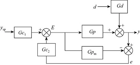
Figure 1Structure of 2DOF-IMC

where k is gain process, τ is time constant of the process, λ1and λ2are filter parameter of the controller, and α is lead parameter of Gc2controller. The parameter of Gc1is designed as standard IMC controller, while the Gc2is designed such that the disturbance can be rejected as soon as possible. These parameters can be easily obtained in the case of no error in the model. However, the setting of parameter becomes a complicated matter if there is an uncertainty model, where all the models developed will always contain inaccuracies or contain uncertainty. The model uncertainty comes from several sources, i.e., the variation of real parameters affecting plant operation, the inherent non-linearity of the processes, the experimental identification of the process and the mathematical model development [7]. In practice the process uncertainty bound can be obtained from input output test on the plant at different operating points [4].
The parameters tuning is very difficult to be performed under the case of model uncertainty. Many researchers have tried at different methods in tuning of standard IMC and 2DOF-IMC based on model uncertainty [2, 4, 7-9]. Stryczek [10] has introduced Maximum peak (Mp)-tuning method which does not involve weighting transfer function as used by Morari and Zafiriou [2]. From the Mp-tuning principle, Stryczek et al. [11] developed IMCTUNE tuning method. IMCTUNE [11] facilitates the design and tuning of 1DOF and 2DOF-IMC, 1DOF and 2DOF-PID, IMC and PID feedback and feedforward and model state feedback (MSF)-IMC controllers [4]. In the case of 2DOF-IMC, IMCTUNE uses partial sensitivity function to tune the disturbance rejection controller [4]. The partial sensitivity function consists of disturbance transfer function [4, 9]. However, the disturbance is very difficult to be modeled and the use of partial sensitivity function is restricted to overdamped system. The IMCTUNE then approximates the disturbance transfer function.
Recent research on the tuning of 2DOF-IMC is very limited. Most of the recent researchers focus on the application of IMC on specific cases rather than on IMC tuning, for example, unstable and integrating processes [12-16], and nonlinear process [17-19]. Therefore, study on tuning of 2DOF-IMC for general purpose (stable process) is needed to develop a tuning method, which simplifies the existing tuning of the 2DOF-IMC under model uncertainty. In this paper, a new tuning method for 2DOF-IMC under parametric uncertainty is highlighted. Maximum peak (Mp) is used for tuning of set point tracking controller (Gc1) and gain margin (GM) is used for tuning of disturbance rejection (Gc2). Then, the proposed tuning method is denoted as Mp-GM method. The tuning is determined based on worst case of an uncertainty process. Three specifications are set to obtain the optimal controller parameters of Mp, λ2/λ1and GM. The values of these specifications are determined based on time response and integral absolute error (IAE) value on the worst case, the no error in the model case and the slowest case. The output responses and the integral absolute error (IAE) values are compared with IMCTUNE [11]. The effectiveness of the proposed Mp-GM tuning method is simulated through a number of different process characteristics, i.e., FOPDT with /1θτ≤, /1θτ? and /1θτ≥ ; second order with underdamped and third order with nonminimum phase process.
This paper is organized as follows. Section 2 describes the relationship between the maximum peak (Mp) and gain margin (GM) that has a close relationship with the stability of a control system, and then the parameters of a controller can be determined using these conceptual theory. Section 3 describes the proposed tuning method. Some specifications are required in the proposed method. The specifications are determined by taking the smallest integral square error of time response of FOPDT model. The FOPDT model is used, because most chemical process can be represented by FOPDT model. Later, the proposed method is tested on more complicated processes, i.e., second order with underdamped and third-order with nonminimum phase models. In the higher order system it will also show the influence of model simplification on time response. Finally, the conclusion of this work is described in Section 4.
2ESSENTIAL RUDIMENTS
2.1Maximum peak (Mp)
Maximum peak (Mp) is defined as the maximum magnitude of the closed-loop frequency response. In general, the magnitude of Mp gives an indication of the relative stability of a stable system. Mp has strong correlation with the time response of system which can be presented in second order transfer function. Normally, a large Mp corresponds to a large maximum overshoot of the step response in the time domain [20]. For most control systems, it is generally accepted in practice that the desired Mp should be in the range between 1 and 1.5 [21].
For the IMC structure [4], the closed-loop response between y and yspcan be expressed as follows:

For the case that there is no error in the model, the Gc parameter can be easily set. For the case at which model uncertainty exists, the principle of Mp can be applied. Brosilow and Joseph [4] proposed that the Mp value is 1.05, and with this Mp value the overshoot in time response domain will be about 10%.
2.2Gain margin (GM)
Gain margin is one of the frequency response specifications to determine the stability of the controlprocess. Gain margin can be described through Nyquist plot of open loop transfer function [Gol(s)]. If G(s) is a forward path and H(s) is the feedback path, the Gol(s) can be written as

In the case of stable open-loop system, the stability of the closed-loop system can be obtained if the frequency response of Gol in Nyquist plot does not circle of point (?1, 0) [21]. Gain margin is also commonly used for tuning the parameters of controller. Typical value of GM for well tuned controller is 1.7-4 [22], or 2-5 [23]. Many researchers [24-27] used GM criteria for PID tuning.
The usage of gain margin for the tuning of 2DOF-IMC has not been previously investigated. This is probably caused by two reasons. Firstly, in the structure of the standard 2DOF-IMC, Gc1is not in the feedback path, but it is in the forward path. On the other hand, from the equation of the closed-loop response, Eq. (3), the open-loop transfer function Gol(s) is Gc2(Gp?Gpm). It seems that Gc1is not involved in the Gol(s), even Gc1is not involved in sensitivity function of 2DOF-IMC.

The second reason for GM has not been used for the tuning of 2DOF-IMC might be due to the case of no error in the model. Gol(s) is equal to 0. In this case, it is not possible to use GM principle for tuning purpose. On the other hand, the form of Gol(s) which contains (Gp?Gpm) has advantageous for analysis of the GM for controller tuning because the gain margin can be used to prove that the system is stable for any process modeling error [28]. Therefore, the use of the gain margin for tuning 2DOF-IMC can be seen as a great opportunity in improving the overall performance.
3THE PROPOSED METHOD
3.1Procedures of Mp-GMtuning method for 2DOF-IMC
The proposed tuning method consists of three steps: (1) to determine the worst case of the model uncertainty; (2) to specify the parameter of set point controller (Gc1) using Mp criteria, and (3) to obtain the parameter of the disturbance rejection controller (Gc2) using GM criteria. The second and third steps are conducted based on the worst case model uncertainty as Gp and no error in the model as Gpm.
The first step is determining the worst case of uncertainty model. The worst case can be found from the limit of the uncertainty model in terms of upper and lower on process model parameters. The worst case is the nearest condition that unstable responses will occurs. This condition usually occurs at the uncertainty model with the larger (upper limit) steady state gain process, the larger (upper limit) time delay and the smaller (lower limit) process time constant. The worst case can be identified at the biggest maximum value of magnitude of frequency response of complementary sensitivity function. When determining the worst case, time filter constant (λ) value is set equal to the time delay of no error in the model.
The second step is specifying the parameter of set point controller (Gc1) using 1DOF-IMC structure based on the Mp-Tuning criteria as follows:
(1) Set λ1(filter time constant Gc1) initial value i.e λ1is set equal to the time delay (θ) of no error in the model divided by 20.
(2) Calculate max T(jω)in the range of frequency ω=10?3-103.
(3) If max T( jω) >1.05 then add λ1with small number, for example λ1+0.01.
The third step is obtaining parameter of disturbance rejection controller (Gc2) using feedback 2DOF-IMC structure, based on the GM criteria as follows:
(1) Set λ2(filter time constant Gc2) smaller than λ1. In this study λ2=0.5λ1was used. It is reasonable value, because in order to give a better performance for disturbance rejection, λ2is always smaller than λ1[4].
(2) Set initial α equal to λ2. Add α with small number such that the value of GM for the open loop system of 2DOF-IMC is equal to 2.4. Here, the open loop system is Gol=Gc2(Gp?Gpm).
The proposed method is called (Mp-GM tuning method) because it uses the principle of Mp criterion for tuning the set point controller (Gc1) and the principle of GM criterion for tuning disturbance rejection controller (Gc2). The number of variables that affect the performance of Mp-GM tuning such as Mp, ratio λ1/λ2and GM values will be demonstrated through the examples below. These examples reflect the first order plus dead time (FOPDT) process with /1θτ=, /1θτ>, and /1θτ<. Difficult higher order, i.e., second order with underdamped and nonminimum phase third order process are also evaluated.
As a comparison standard 2DOF-IMC structure is tuned by using proposed Mp-GM and IMCTUNE [11]. However there are different Gc2parameters for both methods as in the following equation;

3.2Effects of Mp value to output responses
Effects of Mp value to output responses are shown through the case study of FOPDT. Consider a blending system investigated by Chang et al. [29] with θ/τ>1:
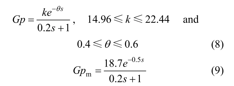
Mp value (AMp) has strong correlation with overshoot. Overshoot (BOS) occurs in the worst case, but not in the nominal and the slowest case. Therefore, the determination of Mp value is based on the overshoot when the set point is introduced to the worst case. To keep the process remains stable in the worst conditions, the overshoot is specified not to exceed 10%. Table 1 presents 2DOF-IMC controller parameter using proposed Mp-GM tuning for various values of Mp and its percentage overshoot. The percentage overshoot is based on output response in Fig. 2.

Table 1Controller parameters and its percentage overshoot
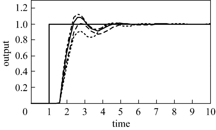
Figure 2Effects of Mp value to output response of FOPDT θ/τ>1IMCTUNE, BOS=1.0125; AMp=1, BOS=1.0026;AMp=1.05, BOS=1.0810; AMp=1.1, BOS=1.1235
The smaller Mp in Fig. 2 gives sluggish control action for no error in the model and slowest case. On the other hand, the larger Mp produces the higher overshoot. It may result in unstable response for the worst case problem. Based on Table 1 and Fig. 2 the appropriate Mp value is 1.05 as Brosilow and Joseph recommended that the maximum overshot is 10% [4].
3.3Effects ofλ2/λ1to output response
Brosilow and Joseph [4] stated that for better disturbance rejection, the value of λ2is always less than λ1. A case study below shows how the ratio of λ2to λ1affects the output responses. The FOPDT model with θ/τ<1 is adopted from Vilanova et al [30]. The uncertainty model is assumed +20%.
The FOPDT model with θ/τ<1 is described as below.
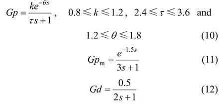
The worst case is at plant with k=1.2, τ=2.4 and θ=1.8. Using the Mp-GM tuning, the value of λ1is 1.8510. The values of λ2and α for the corresponding ratio of λ2to λ1are presented in Table 2. For comparison, the controller parameters of the standard 2DOF-IMC with IMCTUNE λ1, λ2, and α is 0.70304, 0.46536 and 1.4438, respectively.

Table 2The value of λ2and α for the corresponding λ2/λ1
The responses of the worst case, nominal model and slowest case are presented in Figs. 3-5. In these figures, the time responses of specification (λ2/λ1) of Mp-GM tuning method are compared with IMCTUNE as a base case. A unit set point is introduced at time 1 and a magnitude of disturbance of 0.3 is entered to the system at time 20. Figs. 3-5 show that IMCTUNE gives unstable response for worst and slowest case, but it produces very good response (smallest IAE) for no error in the model case. Table 3 shows IAE value of several λ2/λ1of proposed Mp-GM method for the worst, i.e. no error in the model and slowest case. Since the smallest mean of IAE is at λ2/λ1=0.9, λ2/λ1=0.9 is then selected as parameter specification of Mp-GM tuning method.
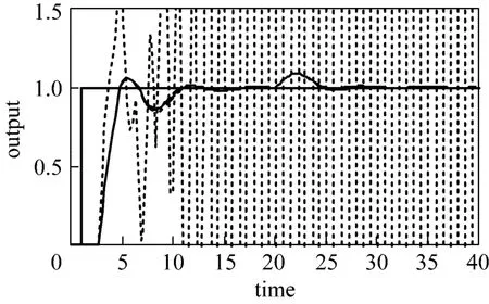
Figure 3The worst case responses for the case FOPDT with θ/τ<1IMCTUNE, IAE=29485.5; λ2/λ1=0.7, IAE=3.4670;λ2/λ1=0.9, IAE=3.4635; λ2/λ1=1.1, IAE=3.5324
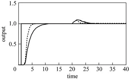
Figure 4Responses of the case FOPDT with θ/τ<1 with nominal modelIMCTUNE, IAE=2.3914; λ2/λ1=0.7, IAE=3.7072;λ2/λ1=0.9, IAE=4.3161; λ2/λ1=1.1, IA E=3.7158

Figure 5The slowest case responses for the case FOPDT with θ/τ< 1IMCTUNE, IAE=37.2992; λ2/λ1=0.7, IAE=4.3450;λ2/λ1=0.9, IAE=3.7110; λ2/λ1=1.1, IAE=4.2919

Table 3Effect of λ2/λ1to output response
3.4Effects ofGMto output response
The effect of GM criteria to the process responses is shown through the case study below. Suppose a FOPDT with θ/τ1? [4], the following equations can be obtained.

The worst case is at plant with k=1.2 and θ=1.2, while the slowest case is at plant with k=0.8 and θ=0.8. The Mp-GM tuning method gives λ1=1.047 and λ2=0.9423. For GM criteria of 1.7, 2.4 and 3.1 (the range is recommended as in previous chapter), the value of α is 2.8623, 2.0223 and 1.5623, respectively. In this process, IMCTUNE produces λ1=1.0352, λ2=0.6022 and α=0.9418.
Figures 6-8 show the responses of the system for the worst, nominal model and the slowest case. A unit set point is entered at time 1 and a disturbance magnitude of 0.3 with transfer function of 1/( 1)s+ is introduced to the system at time 20. In this process, IMCTUNE gives smaller IAE than Mp-GM for the worst and nominal model cases.

Figure 6The worst case responses of FOPDT with θ/τ?1IMCTUNE, IAE=2.4790; GM=1.7, IAE=3.0305;GM=2.4, IAE=2.6299; GM=3.1, IAE=2.5229
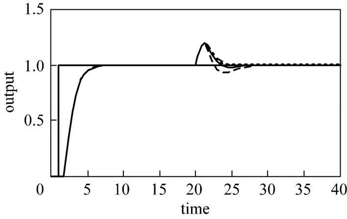
Figure 7Responses of FOPDT with θ/τ?1 with no error in the modelIMCTUNE, IAE=2.4643; GM=1.7, IAE=2.6142;GM=2.4, IAE=2.5150; GM=3.1, IAE=2.5432

Figure 8Output responses of FOPDT with θ/τ?1 for the slowest caseIMCTUNE, IAE=2.8584; GM=1.7, IAE=2.9871;GM=2.4, IAE=2.8545; GM=3.1, IAE=2.9834
The smaller GM values produces more sensitive controller (Figs. 6-8). Based on the Nyquist plot (Fig. 9 for the smallest and Fig. 10 for the largest of GM in the selected range), the smaller GM will yields the graph closer to the critical point (?1, 0). Vice versa, the larger GM will produce a graph at a longer distance from critical point; and hence giving more sluggish controller. The performance of the effect of GM onoutput response is described in IAE value. The corresponding GM at the smallest IAE value is selected. The values of IAE for the worst, nominal model the slowest cases are described in Table 4. It shows that the smallest mean of IAE value is at GM=2.4, then the GM 2.4. Therefore, GM of 2.4 is selected for the best GM specification.
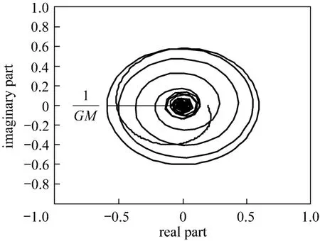
Figure 9Nyquist plot of FOPDT with θ/τ?1, GM=1.7 λ2=0.9423; α=2.8623; GM=1.6963
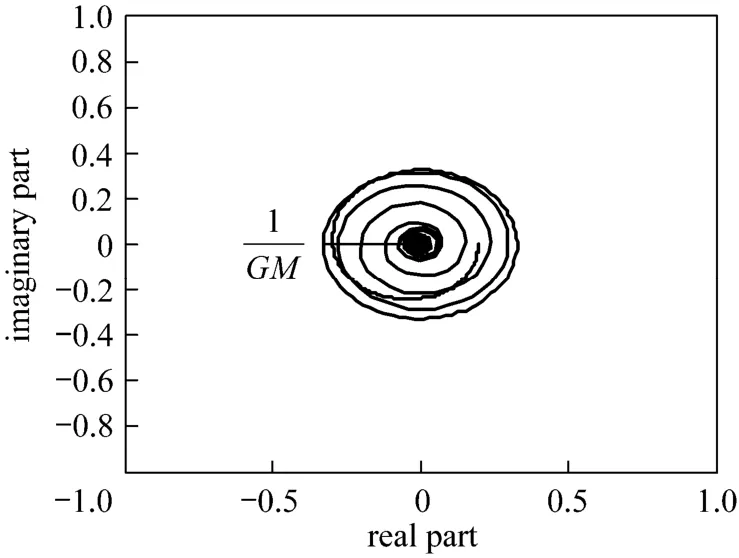
Figure 10Nyquist plot of FOPDT with θ/τ?1, GM=3.1 λ2=0.9423; α=1.5623; GM=3.0996
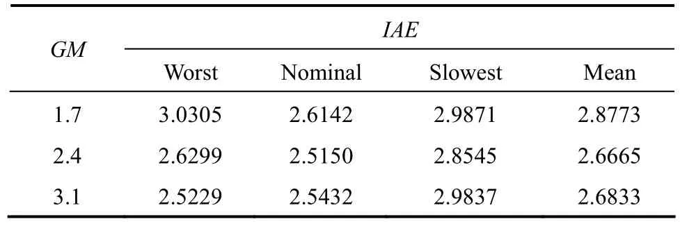
Table 4IAE values at difference GM specification
3.5The effects of simplification model and controller form
3.5.1The second order with underdamped process
The performance of the proposed Mp-GM tuning method is tested on higher-order process, i.e., a second order underdamped process. Second order with underdamped can be found in the non-isothermal of continuous stirred tank reactor (CSTR) process. A dynamic model of non-isothermal of CSTR was developed by Marlin [28]. A transfer function of temperature to coolant flow is expressed as:

Approximation of the above transfer function to FOPDT can be performed with a combination of approaches by Skogestad [31] and Panda et al [32]. Skogestad approach produces the transfer function as follows:

Equation (16) is then simplified by Panda et al. [32], it gives transfer function as follows:

Process uncertainty of the second order process in Eq. (15) is performed by Eq. (18). The value of a and b in Eq. (18) are varies in ±20% from nominal model ones, i.e., ?7.28≤a ≤?4.86 and ?55.00≤b≤?36.67

Two strategies are imposed to design the controller:
(1) Gc and Gpmare in FOPDT form;
(2) Gc is in FOPDT form and Gpmis in the original second order process.
The Mp-GM tuning method produces the worst case plant at a=?4.86 and b=?55.00. For the first strategy (Gc and Gpmare in the form FOPDT) the proposed Mp-GM tuning method results in λ1=0.9715, λ2=0.8744 and α=1.4133. For the second strategy (Gc is in FOPDT form and Gpmis in the original second order process) the proposed Mp-GM tuning method results in λ1=0.9045, λ2=0.8141 and α=2.1496.
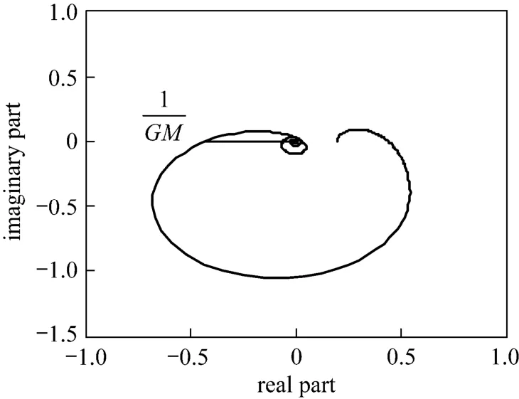
Figure 11Nyquist plot of Mp-GM tuning for underdamp SOPDT system with controller transfer functions are FOPDT formλ2=0.87435; α=1.4133; GM=2.3984
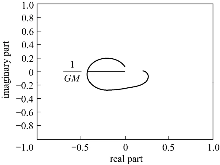
Figure 12Nyquist plot of Mp-GM tuning for underdamp SOPDT system with Gc1is FOPDT form and Gc2is SOPDT formλ2=0.81405; α=2.1496; GM=2.4
Figures 11 and 12 show the Nyquist plot of the two strategies. From these figures, the first strategy (Gc and Gpmare in FOPDT form) has lower degree of stability than the second one (Gc is in FOPDT and Gpmin original form). This is because the Nyquist plot for the first strategy may easily be altered to enclose the point (?1, 0) [21]. However, the above situation occurs when the Mp value is not restricted. In Mp GM tuning method, the Mp value has been appointed 1.05. Then, the stability can be guaranteed.
Comparison of closed-loop responses of the both strategies with IMCTUNE cannot be conducted. It is because IMCTUNE produces the λ2as initial value (any number that is entered to the input). This is a proof that IMCTUNE has its limitation for an underdamp process. Fig. 13 shows the time response when a disturbance magnitude of 0.5 with transfer function of 1/(0.51)s+ is introduced to the system at time 10. Fig. 13 shows that the second strategy gives smaller IAE than the first one.

Figure 13Time response of second order with underdamped process using two form controller strategiesfirst strategy, IAE=1. 3324;second strategy, IAE=1.0658
3.5.2The third order with nonminimum phase process
The proposed method can be imposed to non minimum phase (inverse response) with high order process as described in the case study below. The uncertainty of model parameter is assumed ±20%. The simplification of plant model to FOPDT model is based on Skogestad half rule [31].
Consider non-minimum phase with high order process [31], the following equations can be obtained.
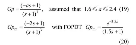
By using a strategy that Gc is in the FOPDT form and Gpmin the original third order with nonminimum phase process, the proposed Mp-GM tuning method generates λ1=4.865, λ2=4.3785 and α=8.2745. The worst case is at plant with zero=2.4.
IMCTUNE obtains very large filter time constants (λ1). Again, this is a proof that IMCTUNE has its limitation for nonminimum phase process. Fig. 14 shows Nyquist plot for the GM criteria of third order with nonminimum phase process on the Nyquist plot. The figure shows that for the minimum phase case, it has more positive phase shift as ω varies [21]. The closed loop stability criteria is also imposed to the system, i.e., the Nyquist path does not enclose the point (?1, 0).
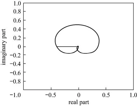
Figure 14GM criteria of third order with nonminimum phase process on the Niquist plotλ2=4.3785; α=12.1695; GM=2.4
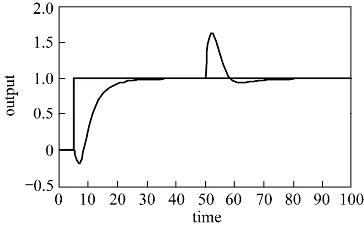
Figure 15Time response of controller design for non minimum phase with high order processproposed method, IAE=11.8995
Figure 15 indicates that the proposed Mp-GM tuning obtains the better controller. These results prove the superiority of the proposed tuning for difficult process (third order process with nonminimum phase). In this type of process, the IMCTUNE does not give realistic parameters value because it produces very large filter time constant or a value as initial input.
4CONCLUSIONS
A new tuning method for 2DOF-IMC has been proposed. The method is called as Mp-GM tuning. There are several specifications that have been specified in the Mp-GM tuning method, i.e., the values of Mp, λ2/λ1, and GM. The best value of Mp is 1.05, λ2/λ1is 0.9, and GM is 2.4. The proposed method was compared and analyzed with IMCTUNE [11]. The proposed method has been successfully implemented to FOPDT and higher order processes. The FOPDT process has varies controllability ratio, i.e., θ/τ≤1, θ/τ?1 and θ/τ≥ 1. The higher processes are second order with underdamped and third order with nonminimum phase process. Although the two of higher order process are difficult processes, the proposed Mp-GM tuning method is able to obtain controller parameter under uncertainty system. In the contrast, IMCTUNE did not give result for underdamped and nonminimum phase system.
ACKNOWLEDGEMENTS
The authors would like to thanks Universiti Malaysia Pahang, Institut Teknologi Sepuluh Nopember Surabaya Indonesia and Universiti Teknologi Malaysia for the providing of joint-research scheme.
NOMENCLATURE
d disturbance input
E error between e and set point
e error between measurement and model
Gc transfer function of controller
Gc1transfer function of set point controller
Gc2transfer function of disturbance rejection controller
Gd transfer function of disturbance
Gp transfer function of process
Gpmtransfer function of model
k gain of process
r order of controller
S sensitivity function
s laplace domain
T complementary sensitivity function
y measurement
yspset point
α lead constant of Gc2controller
β lead constant of adding transfer function
θ time delay
λ filter time constant
τ time constant of process
ω frequency
Subscripts
c controller
m model
p process
1 set point controller
2 disturbance rejection controller
REFERENCES
1 Garcia, C.E., Morari, M., “Internal model control. A unifying review and some new results”, Ind. & En g. Chem. Pro. Des. and Dev.,21(2), 308-323 (1982).
2 Morari, M., Zafiriou, E., “Robust Process Control”, Englewood Cliffs, Prentice Hall, New Jersey (1989).
3 Rivera, D.E., Morari, M., Skogestad, S., “Internal model control: PID controller design”, Ind. & En g. Chem. Pro. Des. and Dev.,25(1), 252-265 (1986).
4 Brosilow, C., Joseph, B., “Techniques of model-based control”, In: Prentice Hall International Series in the Physical and Chemical Engineering Science, Prentice Hall PTR, New Jersey (2001).
5 Smith O, J., “A controller to overcome dead time”, ISA J.6(2), 28-33 (1959).
6 Bin, H, Pingyou, Z., Jun, L., “Multi-loop internal model controller design based on a dynamic PLS framework”, Chin. J. Chem. Eng.,18(2), 277-285 (2010).
7 Laughlin, D.L., Jordan, K.G., Morari, M., “Internal model control and process uncertainty: Mapping uncertainty regions for SISO controller design”, Int. J. Cont.,44(6), 1675-1698 (1986).
8 Liu, K., Shimizu, T., Inagaki, M., Ohkawa, A., “New tuning method for IMC controller”, J. Chem. Eng. Jpn.,31(3), 320-324 (1998).
9 Stryczek, K., Laiseca, M., Brosilow, C., Leitman, M.G., “Tuning and design of single-input, single-output control systems for parametric uncertainty”, AIChE J.,46(8), 1616-1631 (2000).
10 Stryczek, K., “Mp-tuning of internal model control systems under parametric uncertainty”, Ph.D. Thesis, Case Western Reserve University, USA (1996).
11 Stryczek, K., Dong, J., Kumsaen, T., Brosilow, C.B., “IMC-controller tuning program (IMCTUNE)”, 10th edition, Prentice Hall, New Jersey (2002).
12 Chia, T.L., Lefkowitz, I., “Internal model-based control for integrating processes”, ISA T.,49(4), 519-527 (2010).
13 Liu, T., Gao, F., “Enhanced IMC design of load disturbance rejection for integrating and unstable processes with slow dynamics”, ISA T.,50(2), 239-248 (2011).
14 Tan, W., “Analysis and design of a double two-degree-of-freedom control scheme”, ISA T.,49(3), 311-317 (2010).
15 Tan, W., Marquez, H.J., Chen, T., “IMC design for unstable processes with time delays” J. Proc. Cont.,13(3), 203-213 (2003).
16 Wang, R., Watanabe, K., “Three-degree-of-freedom internal model control for unstable process”, In: SICE Annual Conference, Kagawa University, Japan (2007).
17 Cheng, C., Chiu, M.S., “Adaptive IMC controller design for nonlinear process control”, Chem. Eng. Res. and Des.,85(2), 234-244 (2007).
18 Ganeshreddy Kalmukale, A., Chiu, M.S., Luis, P., Antonio, E.,“Data-based internal model controller design for a class of nonlinear systems”, Comp. Aid. Chem. Eng., 1411-1416 (2005).
19 Toivonen, H.T., Sandstr?m, K.V., Nystr?m, R.H., “Internal model control of nonlinear systems described by velocity-based linearizations”, J. Proc. Cont.,13(3), 215-224 (2003).
20 Levine, W.S., “The Control Handbook”, CRC Press, Boca Raton (1995). 21 Kuo, B.C., “Automatic control systems”, 7th edition, Englewood Cliffs, Prentice Hall, New Jersey (1995).
22 Seborg, D.E., Edgar, T.F., Mellicamp, D.A., “Process dynamic and control”, 2nd edition, John Wiley & Sons, USA (2004).
23 Astrom, K.J., Panagopoulos, H., H?Gglund, T., “Design of PI controllers based on non-convex optimization”, Automatica.,34(5), 585-601 (1998).
24 Hang, C.C., Ho, W.K., Cao, L.S., “A comparison of two design methods for PID controllers”, ISA T.,33(2), 147-151 (1994).
25 Ho, W.K., Lim, K.W., Xu, W., “Optimal gain and phase margin tuning for PID Controllers”, Automatica.,34(8), 1009-1014 (1998).
26 Wang, Q.G., Fung, H.W., Zhang, Y., “PID tuning with exact gain and phase margins”, ISA T.,38(3), 243-249 (1999).
27 Yaniv, O., Nagurka, M., “Design of PID controllers satisfying gain margin and sensitivity constraints on a set of plants”, A utomatica.,40(1), 111-116 (2004).
28 Marlin, T.E., “Process Control: Designing Processes and Control Systems for Dynamic Performance”, Chemical Engineering Series, 2nd edition, McGrawHill, Boston (2000).
29 Chang, D.M., Yu, C.C., Chien, I.L., “Coordinate control of blending systems”, IEEE Trans. on Cont. Sys. Tech.,6(4), 495-506 (1998).
30 Vilanova, R., “IMC based robust PID design: Tuning guidelines and automatic tuning”, J. Proc. Cont.,18(1), 61-70 (2008).
31 Skogestad, S. “Simple analytic rules for model reduction and PID controller tuning”, J. Proc. Cont.,13(4), 291-309 (2003).
32 Panda, R.C., Yu, C.C., Huang, H.P., “PID tuning rules for SOPDT systems: Review and some new results” ISA T.,43(2), 283-295 (2004).
10.1016/S1004-9541(13)60564-9
2012-02-08, accepted 2012-09-22.
* Supported by Postgraduate Fellowship of UMP, Fundamental Research Grant Scheme of Malaysia (GRS070120) and Joint Research Grant between Universiti Malaysia Pahang (UMP) and Institut Teknologi Sepuluh Nopember (ITS) Surabaya.
** To whom correspondence should be addressed. E-mail: joecheits@yahoo.com
 Chinese Journal of Chemical Engineering2013年9期
- Chinese Journal of Chemical Engineering的其它文章
- Recent Advances in Separation of Bioactive Natural Products*
- Volumetric and Transport Properties of Aqueous NaB(OH)4Solutions*
- Experimental and Theoretical Studies of CO2Absorption Enhancement by Nano-Al2O3and Carbon Nanotube Particles
- A Novel γ-Alumina Supported Fe-Mo Bimetallic Catalyst for Reverse Water Gas Shift Reaction*
- Treatment of Sebacic Acid Industrial Wastewater by Extraction Process Using Castor Oil Acid as Extractant*
- Halloysite Nanotube Composited Thermo-responsive Hydrogel System for Controlled-release*
