Numerical study of the performance of multistage Scaba 6SRGT impellers for the agitation of yield stress fluids in cylindrical tanks*
AMEUR Houari, BOUZIT Mohamed, GHENAIM Abdellah
1. Laboratoire de Mécanique Appliquée, Faculté de Génie Mécanique, USTO-MB, Oran, Algérie
2. Institut de Technologie, Université Ibn Khaldoun, Tiaret, Algérie, E-mail: houari_ameur@yahoo.fr
3. INSA de Strasbourg-24 Bd de la Victoire-67084 Strasbourg-France
Numerical study of the performance of multistage Scaba 6SRGT impellers for the agitation of yield stress fluids in cylindrical tanks*
AMEUR Houari1,2, BOUZIT Mohamed1, GHENAIM Abdellah3
1. Laboratoire de Mécanique Appliquée, Faculté de Génie Mécanique, USTO-MB, Oran, Algérie
2. Institut de Technologie, Université Ibn Khaldoun, Tiaret, Algérie, E-mail: houari_ameur@yahoo.fr
3. INSA de Strasbourg-24 Bd de la Victoire-67084 Strasbourg-France
(Received October 9, 2013, Revised September 2, 2014)
The 3-D flow fields and power consumption in a vessel stirred by multistage Scaba 6SRGT impeller have been investigated. The Xanthan gum solutions in water were used, which have a shear thinning behavior with yield stress. This study was carried out with the help of a CFD package (CFX 13.0, Ansys Inc.) which is based on the finite volume method to solve the momentum equations. The effects of stirring rate, fluid rheology, impeller number, impeller location and vessel size on the performance of such stirred system are presented. To validate the CFD model, our predicted results have been compared with other literature data and a satisfactory agreement has been found.
Scaba 6SRGT impeller, multistage agitator, yield stress fluid, stirred tank, power consumption
Introduction
Stirred vessels are widely used in metallurgical, mineral, and chemical process industries to perform a variety of operations such as: homogenization, polymerization, crystallization, gas dispersion, heat transfer, etc.. There is a wide range of mixing geometries available for viscous fluids, and the selection of an appropriate design for a given application is not an easy task. Several criteria may be used depending on the process requirements, such as flow field characteristics and specific power consumption. The absence of dead zones is of foremost importance for good homogenization. The multi-impeller vessels, having certain advantages (e.g., better liquid circulation and gas distribution, longer gas residence time and thus, more efficient gas utilization), are ever more often used[1].. Some works have been published using multistage impellers. Aubin and Xuereb[2]investigated the performance of multiple Intermig impeller configuration for mixing Newtonian highly viscous fluids. Their results show that by slightly decreasing the distance between the lower two impellers, fluid exchange between the impellers is ensured down to Re=27. For multiple Intermig impeller, Ekato[3]reported that is recommended by manufacturers to install the Intermigs vertically with a distance of separation of0.5D to effectively mix at Reynolds numbers Re>100. Jahoda et al.[4]investigated the effect of the method of simulation for the prediction of liquid homogenization in stirred tanks by one and two impellers (a six-blade 45opitched blade turbine and a standard Rushton turbine) on a centrally located shaft. For a Newtonian fluid, Kasat and Pandit[5]found that the impeller combination PTD-PTD-DT gives lower mixing time but consumes more power as compared to the PTD-PTD-PTD combination and hence from energy efficiency point of view PTD-PTD-PTD can be recommended. PTDPTD-DT combination gives higher exchange and higher dispersion as compared to PTD-PTD-PTD combination due to its higher power consumption. Xia et al.[6]tested different impeller combinations: downpumping propeller (DPP), 6-curved-blade disc turbine (6CBDT) and 6-arrowy-blade disc turbine (6ABDT). Their results of simulation showed that impeller combination consisting of upper two DPP and one bottom 6CBDT could provide the modest flow field enviro-nment for avermectin fermentation among the tested impeller combinations.
Non-Newtonian fluids are common in industry and even in the human body (such as blood, synovial, saliva and fluid). They play a great role in the pharmaceutical, polymer, materials, and biochemical industries. Shear-thinning fluids with yield stress (viscoplastic) are a common class of non-Newtonian fluids. Such materials are frequently encountered in industrial problems (such as suspensions and pastes).
Very few articles are published on the mixing of non-Newtonian fluids with multistage impellers: Montante et al.[7]used pseudoplastic fluids with pitched bladed turbine, Jin et al.[8]used yield stress fluids with four-bladed impeller. For the viscose fermentation broth, which has a pseudoplastic rheology modeled by the Herschel-Bulkley model, Um and Hanley[9]predicted by CFD the flow patterns in a bioreactor agitated by double-stage Rushton impeller. Their results suggest that there is a potential for slow or stagnant flow between top impellers and bottom of the tank region, which could result in poor nitrogen and heat transfer for highly viscous fermentations. Their results also showed that the axial velocity was significantly improved for the modified geometry in the bottom of the tank.
Woziwodzki et al.[10]studied the mixing efficiency of shear-thinning fluids using carboxy methyl cellulose sodium salt (Na-CMC) aqueous solutions of varying mass concentrations and three types of impellers (Rushton turbine (RT), six-flat-blade turbine (FBT), six-pitched-down-blade turbine (PBT)) which were mounted on a common shaft in combinations of three, four, and five impellers. The mixing time proved to be dependent on the number of impellers as well as on the distance between. Thorough search in the literature suggests that mixing processes by curved bladed impellers for yield stress fluids have received little attention, and a detailed description of such flows and mixing processes is still lacking, despite the importance and utility of these systems.
In this paper, we focus on the hydrodynamics of a vessel stirred by Scaba 6SRGT impellers, for shear thinning fluids with yield stress using CFD. The aim is to determine the performance of such mixing system and then to modify the geometrical configuration so that a wider range of operating conditions can be handled. In order to evaluate the performance of the agitation system, 3-D flow fields, dead zones, cavern size and power consumption have been carried out. The effects of impeller rotational speed, fluid rheology and some design parameters have been investigated.
1. Tank geometry
The tank geometry employed in the work (Fig.1) is a flat-bottomed unbaffled cylindrical tank equipped with six-curved bladed impeller (Scaba 6SRGT). The effect of impeller number has been investigated, all impellers are mounted on a centrally located shaft of diameter ds/D=0.05. Liquid height was kept equal to the vessel heightH=0.4 m. The impeller blade height ish/ D =0.1. The impeller blade diameter is d/ D=0.5. The influence of vessel size has been also studied by realizing five geometrical configurations: H/ D =1, 1.16, 1.33, 1.6 and 2, respectively.
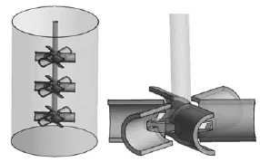
Fig.1 Stirred system
2. Mathematical background
The Xanthan gum solutions in water used in this study have a yield stress behavior modeled by the Herschel-Bulkley model[11].
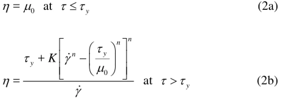
Thus, its apparent viscosity(η)is given by

where τyis the yield stress,γ˙is the shear rate, and K andnare the consistency index and the flow behavior index, respectively.
According to the measurements conducted by Prajapati and Ein-Mozaffari[12], the rheological properties of the Xanthan gum solutions were summarized in Table 1.
The Herschel-Bulkley model used causes a numerical problem during the CFD simulations because the non-Newtonian viscosity becomes unbounded at small shear rate. This behavior causes instability during computation[13]. Thus, the modified Herschel-Bulkley model was employed to avoid the numerical instability. It was assumed that the xanthan gum solution acts as a very viscous fluid with viscosity μ0at τ≤τyand the fluid behavior is described by a power law model at τ>τy[13]

Table1 Rheological properties of xanthan gum solutions
The Metzner-Otto correlation[14]was employed to calculate the modified Reynolds number for the Herschel-Bulkley fluids
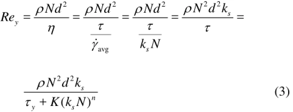
where γ˙avgis the average shear rate and ksis a Metzner-Otto constant.ksis a weak function of impeller type and it was assigned a value of 11.5 for the Scaba impeller[15].
The power consumption is a macroscopic result obtained by integration on the impeller surface of the local power transmitted by the impeller to the fluid

The power number is calculated according to this equation

All variables describing the hydrodynamic state are writing in dimensionless form, the dimensionless forms of velocities, radial(r )and axial(z)coordinates are obtained as follow:V?=V/πND,r?= 2r/ D and z?=z/ D.
3. Numerical methods
In this section, only a brief description of the computational techniques used in this work is presented. Details are given by Ameur et al.[16].
Once the discretization of the flow domain (tetrahedral mesh) has been performed using ICEM-CFD, the CFD solver CFX 13.0, Ansys Inc., is used to obtain values for the velocity components and pressure at each of the node points. The solver uses a full finite volume formulation to solve the fully-coupled mass and momentum conservation equations. The flow fields are solved in a rotating frame of reference in which the flow is time-independent.
Mesh tests were performed by verifying that additional cells did not change the velocity magnitude in the regions of high velocity gradients around the impeller blades by more than 2.5%.
This study is restricted to the laminar and transition regimes, the Reynolds number is varying from 1 to 200. Even if the flow is not fully into the turbulent regime, we should simulate the flow as being turbulent. Fortunately, the turbulent properties vanish when in the laminar flow, so the correct way of simulating in the transitional regime is using a turbulence model. In our study, we have used the SST model. This model has the option of specifying how we model the transition turbulence: it is the fully turbulent, specified intermittency (requiring acquired knowledge), the gamma model or the gamma theta model.
In each simulation, the solution is considered converged when the normalized residuals for the three velocity components and the pressure all fall below 10-6. Calculation of the velocity and pressure fields takes between 90 and 300 iterations to converge and each run takes less than five hours of CPU time. The computations were run in Core i7 CPU 2.20 GHz with 8.0 GB of RAM.
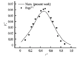
Fig.2(a) Radial velocity for Re=21.5,n =0.12,Z?=0.21,y θ=-45o
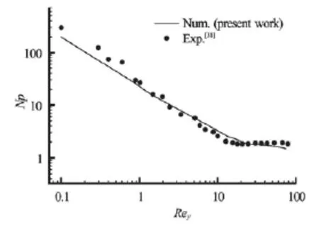
Fig.2(b) Power number for n=0.12
4. Results and discussion
In this study, the performance of multiple curved blade impellers was evaluated on the basis of cavern size and power consumption. First, we have seen necessary to validate the CFD model, for this purpose we have referred to the work of Pakzad et al.[17]. With the exactly same geometrical conditions we predicted the variation of radial velocity along the vessel radius (Fig.2(a)) and the power number for different Reynolds numbers (Fig.2(b)). As observed on this Figure, the validation of our results with those measured by Pakzad et al. shows a satisfactory agreement.
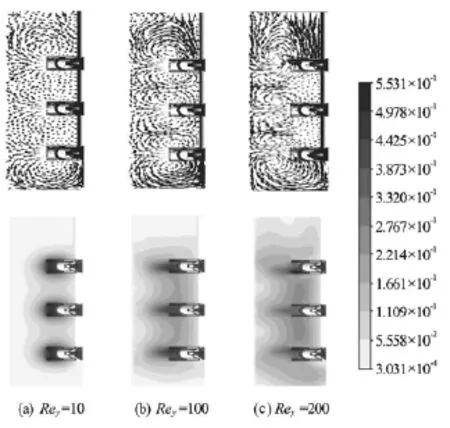
Fig.3 Resultant velocity field for Xanthan gum solutions at 1.5%,H/ D=2
4.1 Effet of Reynolds number
Fundamental studies of mixing in stirred tanks have used experimental, analytical, and numerical approaches, but a complete understanding of laminar mixing is still lacking[18]. Moreover, operating in turbulent regime may not always be feasible. For example, consider polymerization reactions, where due to high viscosities achieving higher Reynolds numbers lead to large increase in power consumption as well as higher torque requirements that may exceed equipment capabilities. In addition, fast stirring rates are highly undesirable in biological processes where materials such as mammalian cells, fibers and proteins are shear sensitive. In such systems, the homogenization process often needs to be performed in the laminar regime.
It is believed that at low Reynolds numbers, mixing is often inefficient[19]. Segregated zones appear even when mixing in complex axial impellers[18], causing several adverse effects: desired reactions may be slowed and even halted before reaching completion, undesired reactions are enhanced, and product selectivity is decreased. A common approach to overcome this problem has been the use of complex impeller geometries for lowRe mixing.
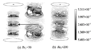
Fig.4 Streamlines for Xanthan gum solutions at 1.5%,H/ D= 2
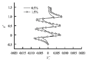
Fig.5 Velocity for Re=40,r?=0.7,H/ D=2y
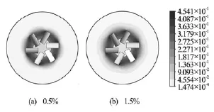
Fig.6 Resultant velocity for Re=40,z?=0.5,H/ D=2y
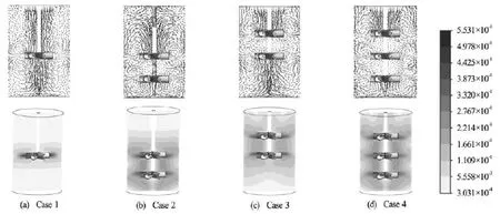
Fig.7 Flow fields for Xanthan gum solutions at 1.5%,H/ D =2,Rey=200
In this paper, the Reynolds number is ranging from 0.1 to 200, covering laminar and transitional regimes. The velocity fields induced for different Reyare presented on Fig.3. In this figure, the three impellers are equally spaced and placed at H/ D=0.5, 1 and 1.5, respectively. As shown, for smallRey(Rey= 10)the flow impinging from the impeller is very weak, which is resulted in caverns limited around the impeller leading to the formation of compartments. But, the increase inRey(Rey=100)yields higher radial flow in the direction of vertical wall of the tank. This flow is then divided in two streams: one upward to the free surface of liquid and the second downward to the vessel base. In the space between impellers and because of the increasing Reynolds number(Rey= 200), the interference of fluid flows is intense which can enhance the mixing.
Another noticeable observation is marked on Fig.4. For low Reyand because of the blade shape (curvature), a thick layer of fluid flow with high shear rates is formed at each blade tip, which can be another cause responsible of the formation of compartment.
4.2 Effect of fluid rheology
Another parameter which has an important effect on the flow fields generated is the fluid rheology. Two cases are chosen to perform the test (Table 1).
The variations of axial velocity along the vessel height are presented on Fig.5, the minus sign means that the liquid is pumped into the bottom of the mixer. As shown, the higher shear rates are located in the area swept by the impeller, and the increase in Xhanthan gum concentration yields higher shear rate in the vicinity of the impeller because of the viscous forces, which generate larger well-stirred region. The contours presented on Fig.6 illustrate this phenomenon more clearly.
4.3 Effect of impeller number and location
As discussed by Szalai et al.[20], one of the most challenging tasks in the process industries is the design and scale up of reactors for processing of non-Newtonian fluids. Here, we examine the effect of impeller number and location. Four geometrical configurations are realized for this issue as shown on Fig.7.
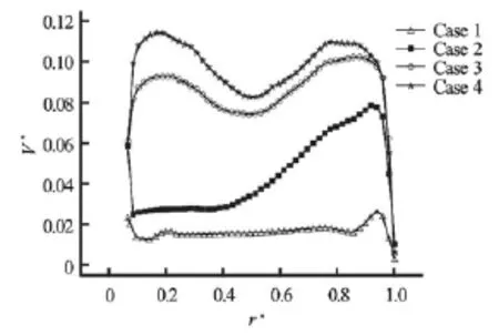
Fig.8 Resultant velocities for Xanthan gum solutions at 1.5%, H/ D =2,Re=200,z?=1.75y
For the first case where just one impeller is used located at the central part of vessel with H/ D=2of height, and although the Reynolds number is important, the axial circulation can’t reach the free surface because of the great ratioH/ D. If another impeller is added at the lower part of vessel atH/ D=0.5(Case 2), that can ensure mixing at this space, but for this configuration, segregated zones are formed at the free surface of liquid leading to poor mixing (Fig.8). With the same stirring rate, these vortices can be eliminated by the placement of another impeller in this area at H/ D=1.5(Case 3). Thus, to ensure agitation in the whole vessel volume, it is necessary to mountain atleast three impellers (equally spaced) for similar slim vessels (H/ D)(Case 4).

Table2 Power number for Rey=20, Xanthan gum solutions at 1.5%,H/ D=2
Concerning the power consumption, as summarized on Table 2, the increase in impeller number is penalizing in power consumption but it is vitally needed to enlarge the cavern size. Another point can be underlined, is the difference in Npbetween Cases 2 and 3: although there are two impellers for both cases, the Case 3 is much consuming because of the wall effect (vessel base).
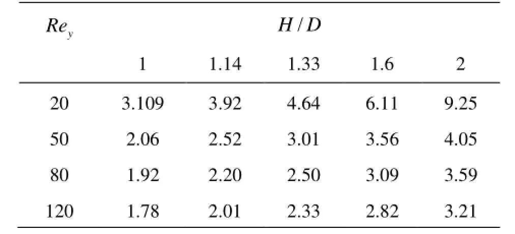
Table3 Power number for different Reynolds numbers and different vessel diameters, Xanthan gum solution at 1.5%
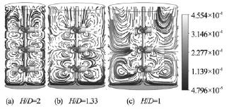
Fig.9 Flow fields for Xanthan gum solutions at 1.5%,Rey= 200
4.4 Effect of vessel size
In this section, the effect of vessel size is discussed with five geometrical configurations as summarized in Table 3. On Fig.9, we remark that the chaotic regions produced between impellers are intensified for the slim vessel (H/ D=2), giving better performance. With continuous increase in vessel diameter, the connection of fluid flows between impellers becomes weak. For the last case(H/ D=1), and because of the excessive increase of vessel size compared to the impeller dimensions, that can’t permit to obtain good homogenization in the whole vessel volume, especially in the lower corners where larger recirculation loops are formed because of the wall effects. The centers of these loops are not disturbed which is unfruitful in term of mixing.
However, the small distance between impeller blades and vessel walls yields to higher energy consumption (Table 3) and this is due to wall effect. Thus the best compromise between cavern size and power consumption is using moderate ratio d/ D.
Another important remark is revealed by results given on Table 3, the power number decreases with increasing Reynolds number and increasing vessel diameter (we remind that the vessel height is kept constant). The value ofNpforH/ D=1is almost three times smaller than forH/ D =2for Rey=20, however this difference becomes smaller with increasing Reynolds number.
5. Conclusions
The hydrodynamics of yield stress fluids in strirred tank by multiple Scaba 6SRGT impellers are studied using CFD. The most important dynamics in such system are those associated with the torus: unmixed regions unable to translate, stretch and contract that represent the primary obstacle to efficient mixing.
The results obtained permit to resume the following conclusions:
For slim vessel, it is necessary to use three impellers located at the bottom, middle and upper part of the vessel to ensure mixing in the whole volume.
The Scaba 6SRGT impeller produces radial flows, so if two or more impellers are mounted vertically on the same shaft (multistage) that results toroidal vortices between them (impellers). On the other hand and because of the curvature blade, it appears a thick layer of high shear rates at the blade tip, leading to the formation of compartments. Thus, the clearance between impellers must be optimized. Here, we suggest that impellers be equally spaced. The same distance can be taken for the off-bottomed clearance of the lower impeller, in order to reduce the wall effect.
The vessel diameter has also an importance effect; the great increase of this parameter is marked by the presence of larger segregated zones leading to poor mixing. Thus, a moderate ratio of d/ Dis should be used.
[1] MOUCHA T., LINEK V. and EROKHIN K. et al. Improved power and mass transfer correlations for design and scale-up of multi-impeller gas–liquid contactors[J]. Chemical Engineering Science, 2009, 64(3): 598-604.
[2] AUBIN J., XUEREB C. Design of multiple impeller stirred tanks for the mixing of highly viscous fluids using CFD[J]. Chemical Engineering Science, 2006, 61(9): 2913-2920.
[3] EKATO. Handbook of mixing technology: General theory, selection criteria, application[M]. Schopfheim, Germany: EKATO Rühr-und Mischtechnik GmbH, 1991.
[4] JAHODA M., MOSTE K. M. and KUKUKOVA A. et al. CFD modelling of liquid homogenization in stirred tanks with one and two impellers using large eddy simulation[J]. Chemical Engineering Research and Design, 2007, 85(5): 616-625.
[5] KASAT G. R., PANDIT A. B. Mixing time studies in multiple impeller agitated reactors[J]. Canadian Journal of Chemical Engineering, 2004, 82(5): 892-904.
[6] XIA J. Y., WANG Y. H. and ZHANG S. L. et al. Fluid dynamics investigation of variant impeller combinations by simulation and fermentation experiment[J]. Biochemical Engineering Journal, 2009, 43(3): 252-260.
[7] MONTANTE G., MO?TEK M. and JAHODA M. et al. CFD simulations and experimental validation of homogenisation curves and mixing time in stirred Newtonian and pseudoplastic liquids[J]. Chemical Engineering Science, 2005, 60(8-9): 2427-2437.
[8] JIN B., LANT P. and GE X. Hydrodynamics and mass transfer coefficient in activated sludge aerated stirred column reactor: Experimental analysis and modeling[J]. Biotechnology and Bioengineering, 2005, 91(4): 406-417.
[9] UM B. H., HANLEY T. R. A CFD model for predicting the flow patterns of viscous fluids in a bioreactor under various operating conditions[J]. Korean Journal of Chemical Engineering, 2008, 25(5): 1094-1102.
[10] WOZIWODZKI S., BRONIARZ-PRESS L. and OCHOWIAK M. Transitional mixing of shear-thinning fluids in vessels with multiple impellers[J]. Chemical Engineering and Technology, 2010, 33(7): 1099-1106.
[11] PAKZAD L., EIN-MOZAFFARI F. and CHAN P. Using electrical resistance tomography and computational fluid dynamics modeling to study the formation of cavern in the mixing of pseudoplastic fluids possessing yield stress[J]. Chemical Engineering Science, 2008, 63(9): 2508-2522.
[12] PRAJAPATI P., EIN-MOZAFFARI F. CFD investigation of the mixing of yield- pseudoplastic fluids with anchor impellers[J]. Chemical Engineering and Technology, 2009, 32(8): 1211-1218.
[13] SAEED S., EIN-MOZAFFARI F. and UPRETI S. R. Using computational fluid dynamics to study the dynamic behavior of the continuous mixing of Herschel-Bulkley fluids[J]. Industrial and Engineering Chemistry Research, 2008, 47(19): 7465-7475.
[14] METZNER A. B., OTTO R. E. Agitation of non-Newtonian fluids[J]. AIChE Journal, 1957, 3(1): 3-10.
[15] AMANULLAH A., HJORTH S. A. and NIENOW A. W. Cavern sizes generated in highly shear thinning viscous fluids by Scaba 3SHP1 impeller[J]. Food and Bioproducts Processing, 1997, 75(4): 232-238.
[16] AMEUR H., BOUZIT M. and HELMAOUI M. Numerical study of fluid flow and power consumption in a stirred vessel with a Scaba 6SRGT impeller[J]. Chemical and Process Engineering, 2011, 32(4): 351-366.
[17] PAKZAD L., EIN-MOZAFFARI F. and CHAN P. Using computational fluid dynamics modeling to study the mixing of pseudoplastic fluids with a Scaba 6SRGT impeller[J]. Chemical Engineering and Processing, 2008, 47(12): 2218-2227.
[18] ARRATIA P. E., LACOMBE J. P. and SHINBROT T. et al. Segregated regions in continuous laminar stirred tank reactors[J]. Chemical Engineering Science, 2004, 59(7): 1481-1490.
[19] LAMBERTO D. J., ALVAREZ M. M. and MUZZIO F. J. Experimental and computational investigation of the laminar flow structure in a stirred tank[J]. Chemical Engineering Science, 1999, 54(7): 919-942.
[20] SZALAI E. S., ARRATIA P. and JOHNSON K. et al. Mixing analysis in a tank stirred with EkatoIntermig impellers[J]. Chemical Engineering Science, 2004, 59(18): 3793-3805.
* Biography: AMEUR Houari (1982-), Male, Ph. D., Assistant Professor
 水動(dòng)力學(xué)研究與進(jìn)展 B輯2015年3期
- 水動(dòng)力學(xué)研究與進(jìn)展 B輯的其它文章
- United friction resistance in open channel flows*
- Ski jump trajectory with consideration of air resistance*
- Selection of organic Rankine cycle working fluids in the low-temperature waste heat utilization*
- Stability of a tumblehome hull under the dead ship condition*
- Multi-scale Runge-Kutta_Galerkin method for solving one-dimensional KdV and Burgers equations*
- The impact of macroalgae on mean and turbulent flow fields*
