Modied Omega-K algorithm for processing helicopter-borne frequency modulated continuous waveform rotating synthetic aperture radar data
Dong Li,Guisheng Liao,Yong Liao,*,and Lisheng Yang
1.Key Laboratory of Aerocraft Tracking Telemetering&Command and Communication,Ministry of Education, Chongqing University,Chongqing 400044,China;
2.National Lab of Radar Signal Processing,Xidian University,Xi’an 710071,China
Dong Li1,Guisheng Liao2,Yong Liao1,*,and Lisheng Yang1
1.Key Laboratory of Aerocraft Tracking Telemetering&Command and Communication,Ministry of Education, Chongqing University,Chongqing 400044,China;
2.National Lab of Radar Signal Processing,Xidian University,Xi’an 710071,China
With appropriate geometry conguration,helicopterborne rotating synthetic aperture radar(ROSAR)can break through the limitations of monostatic synthetic aperture radar (SAR)on forward-looking imaging.With this capability,ROSAR has extensive potential applications,such as self-navigation and self-landing.Moreover,it has many advantages if combined with the frequency modulated continuous wave(FMCW)technology. A novel geometric conguration and an imaging algorithm for helicopter-borne FMCW-ROSAR are proposed.Firstly,by performing the equivalent phase center principle,the separated transmitting and receiving antenna system is equalized to the case of system conguration with antenna for both transmitting and receiving signals.Based on this,the accurate two-dimensional spectrum is obtained and the Doppler frequency shift effect induced by the continuous motion of the platform during the long pulse duration is compensated.Next,the impacts of the velocity approximation error on the imaging algorithm are analyzed in detail,and the system parameters selection and resolution analysis are presented.The well-focused SAR image is then obtained by using the improved Omega-K algorithm incorporating the accurate compensation method for the velocity approximation error.Finally, correctness of the analysis and effectiveness of the proposed algorithm are demonstrated through simulation results.
helicopter-borne rotating synthetic aperture radar (ROSAR),frequency modulated continuous wave(FMCW),improved Omega-K algorithm,two-dimensional spectrum.
1.Introduction
Synthetic aperture radar imaging is widely used on many platforms.With the ability of vertical takeoff,low altitudeight and landing,the helicopter becomes the best maneuverability air transport platform only if the weather conditions are good enough.Due to the absence of reliable obstacle detection instruments on theight path and landing sites in adverse weather conditions,ight safety and landing of the helicopter will be seriously threatened,and thus such dangerous targets detection devices are strongly desirable.Combining the frequency modulated continuous wave(FMCW)technology,featured by high reliability,highcompact,low cost,andstrongadaptationabilityto the environment and climate changes,with the helicopterbornerotating synthetic aperture radar(ROSAR),effective andreliable dangeroustargetsdetection can be guaranteed. And it becomes the best choice for the helicopter collision avoidance system and is widely studied in all the countries [1–3].
Restricted by the illuminating geometry,conventional synthetic aperture radar(SAR)can only image parts of the right or left areas of theight path,and the front blind area is inherently unavoidable[4].Even though the forward looking SAR has the ability to image the front interested areaoftheightdirection,the azimuthresolutionis always limited by the relative distance and the antenna aperture [5,6].Besides,the complexity and cost of the hardware make it not quite suitable for practical implementations. The rotating SAR is an important imaging mode based on the rotating antenna[7],which wasrstly put forward by theGermanSpaceAgency[8,9].It is characterizedbyhigh spatial and temporal resolution,short revisit period,widearea imaging ability,low cost and so on.Particularly,the light weight and compact size make it quite suitable to the helicopter-borneplatform,and in some cases,the radar antenna can be mounted at the end of the helicopter rotor blades or rigid brackets which further simplify the cong-uration of the platform.With the rotation of the antenna, a 360°imaging of the space area can be obtained without the necessity of generally required forward movement of the helicopter platform.The time-domain imaging method has been used frequently since it was proposed[9],but it suffers great computation burden and is not suitable for the real time implementation.Subsequently the proposed sub-aperture imaging method also suffers low resolution [10].An efcient imaging algorithm for FMCW-ROSAR still needs further investigation with much urgency.
In this paper,based on the helicopter-borne FMCWROASR imaging geometry model,the separated transmitting and receiving antennas system is equalized to the case of a system with only one antenna for both transmitting and receiving using the principle of the equivalent phase center.Then,an accurate two-dimensional spectrum is obtained and the Doppler frequency shift effect induced by the continuous motion of the platform while radar transmits and receives signals is compensated.Next,the impacts of the velocity approximation error on the imaging algorithm are analyzed in detail,and the system parameters selection and resolution analysis are presented. Then,the well-focused SAR image is obtained by using the improved Omega-K algorithm incorporating the accurate compensationmethod for the effect of the velocity approximation error.Finally,effectiveness of the proposed algorithm is demonstrated through simulation results.
2.Helicopter-borne ROSAR imaging description

Fig.1 ROSAR basic geometric confguration
3.Helicopter-borne FMCW-ROSAR imaging geometry
In this section,a novel imaging mode for helicopter-borne rotating synthetic aperture radar combined with the frequency modulated continuous wave technology is presented.Fig.2 shows the geometry conguration of the helicopter-borne FMCW-ROSAR,where the transmitter and receiver antennas(marked as□and△)are mounted at the tips of the two mutually perpendicular helicopter rotor blades to eliminate the mutual interferenceof the transmitter and receiverchannel,respectively.Accordingto this setting,the trajectory of the antenna phase center motion is circular with constant angular velocity ω and the radius L.In this case,the equivalent phase center locates at the midpoint of the baseline between the transmitter and the receiver.With the motion of the rotating antenna,an annulus illuminating area is generated with an inner radius r1, outerradiusr2,andcenterradiusr0demonstratedinFig.2, and all these parameters are dependent on the platform altitude H,depression angle φ and the beamwidth ε in the elevation direction.That is


Fig.2 Geometry confguration of FMCW-ROSAR
Denoteτ as theazimuthslowtimevariable,andsuppose that the beam center passes the positivepart of the x axis at the instant τ=0.Moreover,the beam center illuminates apoint target P at the coordinate of(rpcosθp,rpsinθp,0) at time τ=τp,where rpand θpdenote the radius and the angle versus the radius of the point target P in polar coordinates format,respectively.Now suppose the radar antennas mounted at the tip of the rotator blades transmit the frequency modulated continuous wave,and then the history of the transmitter antenna phase center can be written by

with θT=ωτ+45°is the instantaneousangleof the transmitter antenna phase center.
Similarly,the history of the receiver antenna phase center is given by

where θR=ωτ?45°is the instantaneous angle of the receiver antenna phase center.
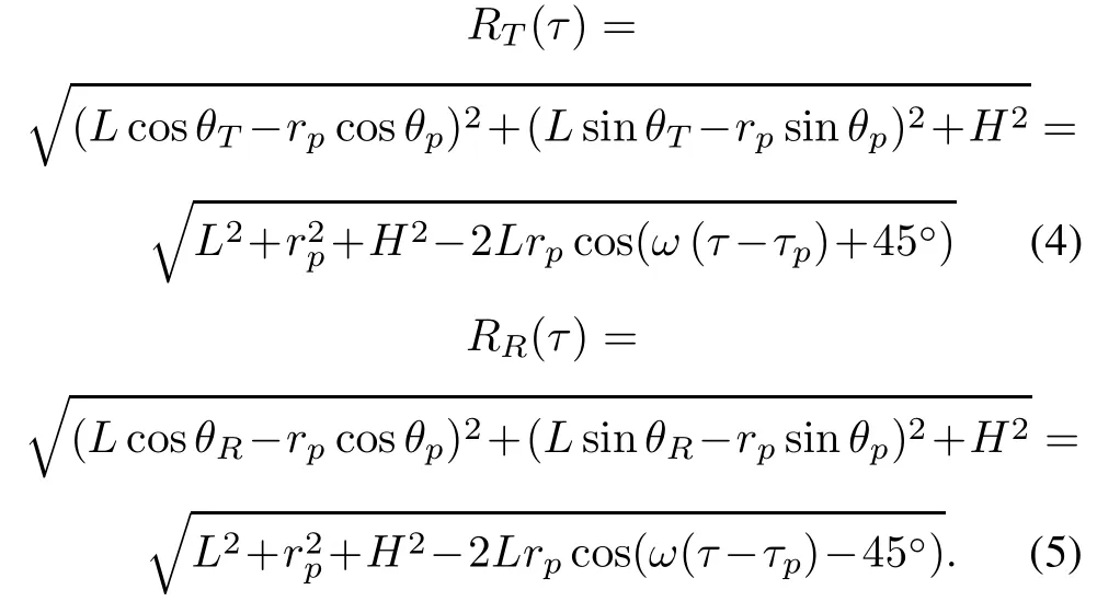
Then the immediate slant range from the target P to the transmitter and receiver at time τ can be expressed respectively as follows:
4.Bistatic to monostatic equivalence processing
As illustrated in Fig.2,since the transmit antenna and the receive antenna of the FMCW ROSAR are separated,it can be considered that the radar works in a bistatic-like case.With the assumption that the slant ranges from the transmitter to the target and that of from the target to the receiver are far from that the relative distance between the two antennas,the bistatic-like mode can be transformed to a monostic one with the equivalent phase center at the midpoint of the baseline as shown in Fig.3.However,with this transformation,a constant phase term is introduced as derived in(8)and it must be compensated as well[11].

Fig.3 Basic principle of bistatic to monostatic equivalence
According to the previously stated geometric model, the coordinate of the equivalent antenna phase center [xequa(τ),yequa(τ),zequa(τ)]can be readily obtained as

And the equivalent slant range is given by
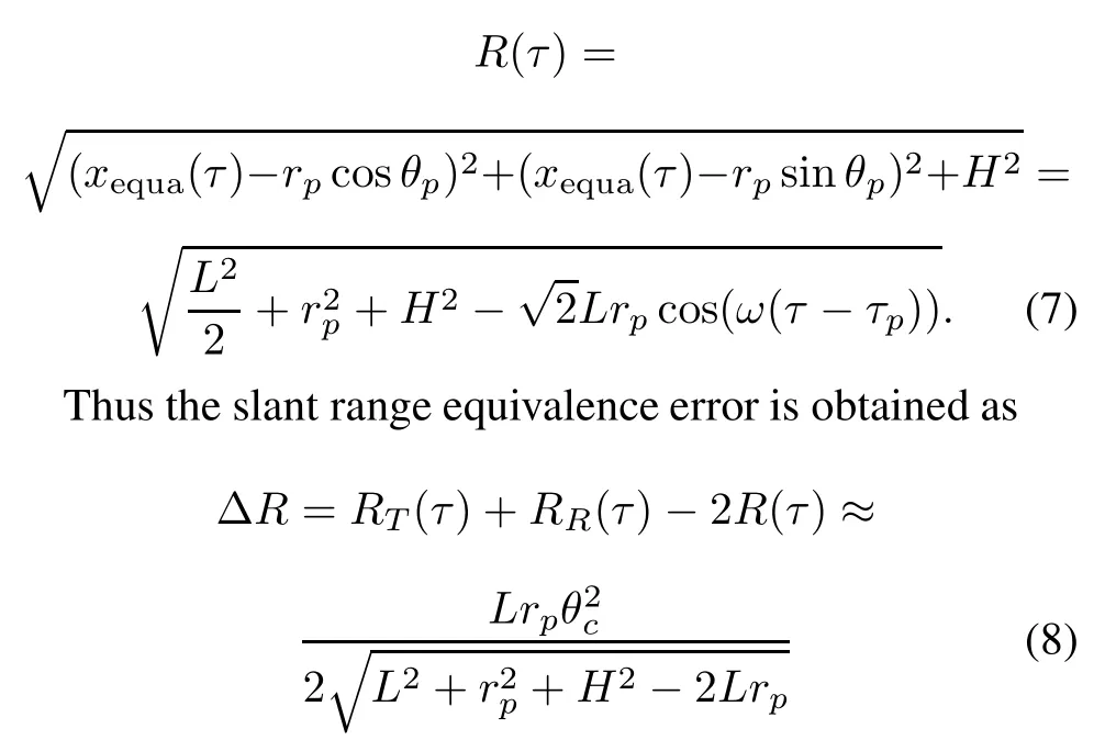
with θc=45°×π/180°is a constant angle.
In this case,the constant phase term needs to be compensated since the equivalence becomes ?=4πΔR/λ, where λ denotes the carrier wavelength.The synthetic aperture length is usually much smaller than the corresponding slant range and the value of ? is generally much smaller than π/4,which can be neglected without causing muchphase errorandperformancedegradation.Therefore, the received data can be treated as obtained from a monostatic congurationwithoutanycompensation.This pointis demonstrated in Fig.4(a)and Fig.4(b)in which the slant rangeequivalenceerrorandcorrespondingquadraticphase error(QPE)are provided,with the parameters listed in Table 1.Obviously,the equivalence error is small and can be ignored.

Fig.4 Slant range equivalence error analysis

Table 1 Simulation parameters
From(7),the accurate analytical spectrum expression cannot be easily derived using principles of the stationary phase(POSP)since there is a cosine term in the equivalent range expression.With the approximation of(cosx= 1?x2/2+x4/24+···)and rp?L,expanding(7)with a Taylor series expansionand ignoringthe forth and higher order terms,yield


5.Helicopter-borne FMCW-ROSAR received signal analysis
5.1Two-dimensional frequency domain signal expression
In the pulsed SAR,the start/stop operation mode is commonly assumed,where the instantaneous slant range from theantennato the targetis assumedto remainconstantduring the pulse time.Moreover,in the FMCW SAR the instantaneous slant range can no longer be assumed to be constant due to the long transmitted signal duration.To develop the signal model for the FMCW-ROSAR system, werst perform an analysis of the two-way delay time τd. The signal is transmitted at time τ with an instantaneous slant range R(τ)and reected back to the receiver at time τ+τdwith the slant range from the target to the receiver R(τ+τd).Thus,the two-way delay time is

where c is the speed of light.The R(τ)and R(τ+τd)are expressed as

Substituting(11)and(12)into(10),a quadraticequation in terms of τdis realized and the solution of τdis obtained as


Suppose that the radar transmits the linear frequency modulated continuous wave(LFMCW)signal,which is dened as sst(tr)=exp(j(2πf0tr+πKrt2r)).Then the received signal can be expressed aswhere σ denotes the back scattering coefcient of the target,tris the fast time variable,Kris the range frequency modulation rate and f0is the carrier center frequency.

To reduce the sampling requirements,data rate and memory of storage,the dechirp-on-receive technology is generally adopted in the FMCW-ROSAR system[12,13]. Therefore,the echo signal after dechirp processing can be expressed as

where τc=2μRc/c is the time delay of the reference target,Rcis the reference range,which is generally dened as the closest slant range from the scene center to the radar platform.The last exponential term of(16)is known as a residual video phase(RVP)term,and can be removed by simple Fourier transformation and phase multiplication [14].The following derivation assumes that the RVP is removed.
Performing the time-frequency substitution of Kr(tr?τc)→fr,yields
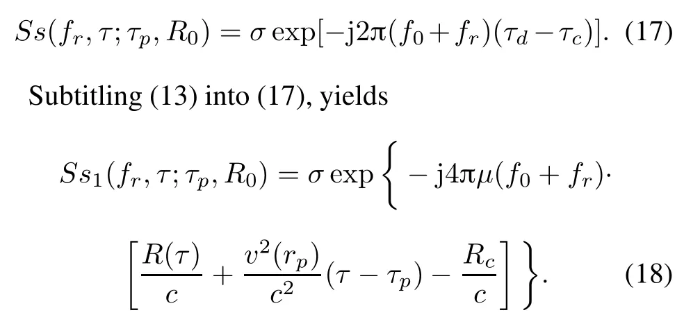
Taking an azimuth Fourier transform(FT)to(18)and using the POSP[15],the two-dimensional frequency spectrum can be written as[16]


Fig.5 Impacts of velocity approximation error
where the phase term Φ(fr,fτ;τp,R0)can be expressed as
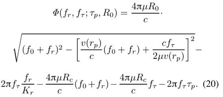
A few important observations can be made from (20).First,the square root contains an additional term (v(rp)/c)(f0+fr),which is not presented in the pulsed SAR spectrum expression and will cause the skew of the two-dimensional spectrum along the range frequency direction if not properly handled.It is introducedby the continuousmovementof the antennaduringthe longpulse duration.Second,the term?2πfr/Krfτin(20)is a rangeazimuthrangewalk terminthe two-dimensionalfrequency domain,which is generated by the variation of the slant range during the pulse duration.This term also marks the difference between the FMCW and the pulsed SAR system.Third,the term?2πfττpis linearly dependent on the zero-Doppler time of the target and thus determines the azimuth registration position of the target after azimuth compression.Fourth,the term?4πμRc/c(f0+fr) and?4πμRcfτ/c refer to the constant range and azimuth shifts,respectively,which are introduced by the dechirpon-receive operation in the FMCW SAR system.
5.2Range-dependent velocity analysis
From(9),one can see that the range-dependent velocityvaries with the target ground position in Helicopter-borne ROASR.To clearly observe this point,the relationship between velocity v(rp)and the target ground position rp(simulation parameters are shown in Table 1)is presented in Fig.5(a).
Obviously,as observed,the range-dependent platform velocity is variable during the synthetic aperture time. Therefore,available imaging algorithms designed for traditional stripmap SAR requiring a constant velocity within the imaging area cannot perform well for ROSAR.Intuitively,one can replace the variant velocity by a constant one using the velocity of the target at the scene center for simplicity.However,this simple operation leads to imaging quality degradation when the velocity cannot be represented by a constant value any more.As analyzed before, sincethedominanterrorscomefromtheresidualrangecell migration(RCM)and QPE caused by the velocity approximation error[17],only those two factors are discussed in the following.
Assuming that δθ and δrpare the target range and azimuth offsets,respectively,from the target to the reference point A at the(θref,rref),the corresponding slant range andequivalentvelocityofapointtargetlocatedat(δθ,δrp) are R(θref+δθ,rref+δrp)and v(θref+δθ,rref+δrp), respectively.
Since there is no squint in ROSAR,the residual linear RCM of a target with an exposure time Tais ΔRlrcm(δθ,δrp)=0,the residual quadratic RCM of the target is

Because RCM correction(RCMC)is fully corrected for target A,the residual RCM of the target at(δθ,δrp)is the sum of the residual linear and quadratic components,and it is given by

Within a processing block,the residual RCM should be kept within a fraction of one range resolution cell ρr.Let this fraction be γrcm,which is nominallyset to be less than 1/2.The maximum range deviation Δrrcmfrom the reference target A is found from the following inequality

Moreover,within a processing block,the QPE should be limited by γqpeπ,where γqpeis nominally set to be less than 1/4.As the QPE is dominated by the residual quadraticRCM,themaximumrangedeviationΔrqpefrom the reference target A is found from the inequality

To observe the effect of residual RCM and QPE,their curves along with the target ground position caused by the velocity approximation are demonstrated(simulation parameters as shown in Table 1)in Fig.5(b)and Fig.5(c). It can be seen that the residual RCM is much smaller than a quarter of range resolution cell.Therefore,it can be neglected without affecting thenal image quality.However, the QPE increases dramatically with the target ground position and is much bigger than π/4 at the marginal area. Thus it must be considered in imaging algorithm design to obtain well-focused SAR images for wide swath cases.
6.FMCW-ROSAR imaging based on improved Omega-K algorithm
The traditional Omega-K algorithm is invalid in processing the FMCW-ROSAR data due to the antenna continuous motion and the characteristic that the velocity changes with the target position as shown in Section 5.In order to overcomethisproblem,animprovedOmega-Kimagingalgorithm is presented in this paper.Theowchart for imaging processing is presented in Fig.6.Each step is outlined as follows.
(i)Bistatic to monostatic equivalence processing and the detailed processing procedures can be found in Section 4.
(ii)Remove RVP.This operation requires range FT, chirp phase multiplication and range inverse Fourier transform(IFT).Thedetailedremoveoperationprocedureis described in[12].
(iii)Take the azimuth FT to transform the raw data into the two-dimensional frequency domain.
(iv)Reference function multiplication(RFM).It is carried out to remove the range-invariant phase(i.e.bulk range walk,constant azimuth shift,azimuth modulation, bulk RCM and bulk secondary range compression(SRC)). Usually,the RFMlter is expressed as

where ?RFM(fr,fτ,Rc)is written as

where Rcdenotes the reference range,which is generally dened as the closest slant range from the scene center to the radar platform.By utilizing RFM multiplication,thetargets at the reference range are completely focused,but the targets away fromthe referencerangeare onlypartially focused and must be further compensated.After RFM processing,the remaining signal becomes

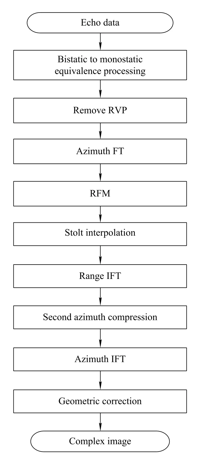
Fig.6 Block diagram of the improved Omega-K focusing algorithm
The phase term ΦRFM(fr,fτ;τp,R0)is formulated as
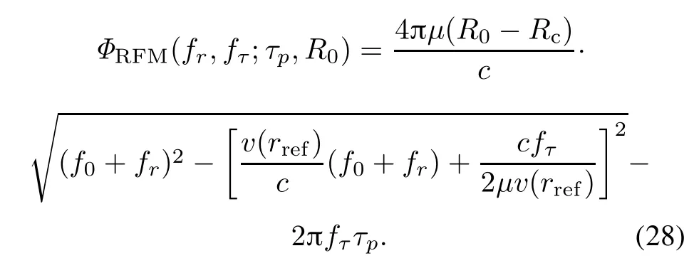
From(28),it can be observed that the range-invariant phase and the range walk caused by the antenna continuous motion are completely removed by RFM.However, the additional term(v(rp)/c)(f0+fr)introduced by the continuousmovement of the antenna during the long pulse duration still exists,which can be corrected by Stolt interpolation in next step.
(v)Perform the Stolt interpolation.After removing the range walk by RFM,the conventionalOmega-K algorithm can be directly applied to focus FMCW SAR data.For the improved Omega-K algorithm,the Stolt interpolation needs to be performed to remap the range frequency variable and is formulated as


From(30),the range–azimuth coupling and azimuth modulationare completely removedby the Stolt interpolation operation.In above processing,the variant velocity is replacedbyaconstantoneusingthevelocityofthetargetat the scene center.However,this replacement will introduce residual RCM and QPE as discussed in Section 5,which means the targets away from the reference range cannot be well focused.The compensation for the errors introduced by velocity approximation processing will be discussed in the following.
(vi)Range IFT.Transforming the signal into the range-Doppler domain by taking the range IFT,obtains

where wr(·)is the compressed pulse envelope in the range direction.
(vii)Second azimuth compression.In order to compensatetheQPEcausedbyvelocityapproximationprocessing, onecan construct an azimuthsecondcompressionfunction as

(viii)Azimuth IFT.Transforming the signal into the complex image domain by performing the azimuth IFT, yields

where wa(·)is the compressed pulse envelope in the azimuth direction.As shown in(33),the target range position error still exists in thenal SAR image.To remove this error,an extra geometric correction operation is necessary for moving targets to their real range positions.
7.Simulated data processing and analysis
To verify the ability of the proposed method to process the FMCW-ROSAR data,experimentswith simulated data using helicopter-borne SAR parameters given in Table 1 are carried out.The simulation scene uses an array of nine targets,which are located in a 600 m×40°grid in the ground plane in range/azimuth direction,as shown in Fig.7.All targets are laid out on a circular arcs grid with an interval of 300 m in range and 20°in azimuth.In the imaging,the point target(PT)2 located at the scene center is selected as the reference target.
Simulateddataare processedbythe Omega-Kalgorithm proposed in[16]and our proposed algorithm.To observe the compressed target properties more clearly and make a fair comparison,no weighting function or sidelobe control approach is used.Fig.8 shows the imaging results of PT1, PT2,and PT3,which are obtained by the Omega-K algorithm in[16]without dealing with the residual RCM and the QPE caused by the velocity approximation error.It is found that due to lacking the compensation of QPE,the azimuth is unfocused.Moreover,as the distance from the target to the reference position increases,the targetfocusing quality degrades quickly due to the inuence of the mismatched azimuth FM rate.Fig.9 shows the imaging result obtained by the proposed algorithm.Since the mismatched azimuth FM rate impact caused by the velocity approximation error is removed via adopting the second azimuth compression,the focusing quality of targets is greatly improved.
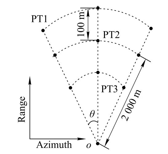
Fig.7 Point targets distribution

Fig.8 Imaging results using the omega-K method in[16]

Fig.9 Imaging results using our proposed method

Fig.10 Point targets imaging results
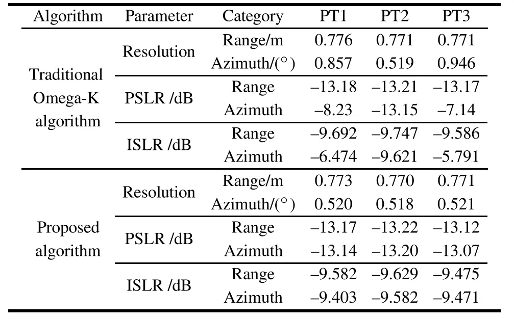
Table 2 Performance analysis
8.Conclusions
Helicopter-airborne rotating SAR imaging,an important work mode of the imaging radar system,can fulll the blind spot of conventional SAR via particular antenna conguration,and image the area in front of theight trajectory.Combining with the FMCW technology,the helicopter-airborne rotating synthetic aperture imaging radarsystemhasthecharacteristicsofhighcredibility,high compactness and low cost.In this paper,a novel imaging mode and an improved imaging algorithm are developed. Firstly,by performing the equivalent phase center principle,the separated transmitting and receiving antenna system is transformedto the case of system congurationwith antenna for both transmitting and receiving signals.Based on this transformation,the accurate two-dimensionalspectrum is obtained and the Doppler frequency shift effect induced by the continuous motion of the platform during the long duration is compensated.The impacts of the velocity approximationerror of the imagingalgorithm are analyzed in detail and the well-focused SAR image is obtained by using the improvedOmega-K algorithm.The effectiveness of the proposed algorithm is demonstrated by simulation results.
[1]S.Sutrisno,E.Joelianto.Model predictive control for obstacle avoidance as hybrid systems of small scale helicopter.Proc.of the 3rd International Conference on Instrumentation Control and Automation,2013:28–30.
[2]Y.K.Kwag,J.W.Kang.Obstacle awareness and collision avoidance radar sensor system for low altitudeying vehicle. Proc.of the 23rd IEEE Conference on Dependable,Autonomic and Secure Computing,2004:20–25.
[3]V.Ziegler,F.Schubert,B.Schulte.Helicopter near-eld obstacle warning system based on low-cost millimeter-wave radar technology.IEEE Trans.on Microwave Theory and Techniques,2013,61(1):658–665.
[4]G.C.Sun,X.W.Jiang,M.D.Xing.Focus improvement of highly squinted data based on azimuth nonlinear scaling.IEEE Trans.on Geoscience Remote Sensing,2011,49(6):2308–2322.
[5]J.Mittermayer,M.Wendler,G.Krieger.Sector imaging radar for enhanced vision(SIREV):simulation and processing techniques.Proc.of the 2nd International Symposium on Image and Signal Processing and Analysis,2001:377–382.
[6]H.Y Lee,J.H.Lee,K.E.Kim,et al.Development of truckmounted arc-scanning synthetic aperture radar.IEEE Trans.on Geoscience Remote Sensing,2014,52(5):2773–2779.
[7]L.L.Kou,X.Q.Wang,J.S.Chong.Circular SAR processingusing an improved Omega-K type algorithm.System Engineering and Electronics,2010,21(4):573–579.(in Chinese)
[8]W.K.Steck,A.P.Wolframm.HeliRadar-a rotating antenna synthetic aperture radar for helicopter all weather operations. Proc.of the AGARD 59th Guidance and Control Panel,1994: 56–62.
[9]H.Klausing,W.Keydel.Feasibility of synthetic aperture radar with rotating antennas(ROSAR).Proc.of the IEEE International Radar Conference,1990:51–56.
[10]B.Sun,Y.Q.Zhou,J.Chen.Operation mode of circular trace scanning SAR for wide observation.Journal of Electronics and Information Technology,2008,30(12):2805–2808.(in Chinese)
[11]Y.Liang,H.X.Wang,Z.Bao.An approach to forward looking FMCW radar imaging based on two-dimensional Chirp-Z transform.Science China:Information Sciences,2010,53(8): 1653–1665.
[12]A.Meta,P.Hoogeboom,L.P.Ligthart.Signal processing for FMCW SAR.IEEE Trans.on Geoscience Remote Sensing, 2007,45(11):3519-3532.
[13]Z.H.Jiang,K.Huangfu,J.W.Wan.A chirp transform algorithm for processing squint mode FMCW SAR data.IEEE Geoscience Remote Sensing Letters,2007,4(3):377–381.
[14]W.G.Carrara,R.S.Goodman,R.M.Majewski.Spotlight synthetic aperture radar signal processing algorithms.Boston, MA:Artech House,1995.
[15]B.C.Liu,T.Wang,Q.S.Wu.Bistatic SAR data focusing using an Omega-K algorithm based on method of series reversion.IEEE Trans.on Geoscience RemoteSensing,2009,47(8): 2899–2912.
[16]R.Wang,O.Loffeld,H.Nies.Focus FMCW SAR data using the wavenumber domain algorithm.IEEE Trans.on Geoscience Remote Sensing,2010,48(4):2109–2118.
[17]H.F.Wong,G.C.Ian,Y.L.Neo.Focusing bistatic SAR data using the nonlinear chirp scaling.IEEE Trans.on Geoscience Remote Sensing,2008,46(9):2493–2505.
Biographies

Dong Li was born in 1983.He received his B.S. degree in automation from Chengdu University of Information Technology,Chengdu in 2007,his M.S.degree in signal processing from Sichuan University,Chengdu,in 2010 and his Ph.D.degree in radar signal processing from Xidian University, Shannxi,in 2014.He is now a lecturer in the Key Laboratory of Aerocraft Tracking Telemetering& Command and Communication,Ministry of Education,at Chongqing University.His research interests include array signal processing,synthetic aperture radar imaging and ground moving target indication.
E-mail:lidongcuit@126.com

Guisheng Liao was born in 1963.He received his B.S.degree from Guangxi University in 1985,and his M.S.and Ph.D.degrees from Xidian University, Xi’an,China,in 1990 and 1992,respectively.He is currently a professor with Xidian University,where he is also a dean of School of Electronic Engineering.He has been a senior visiting scholar with the Chinese University of Hong Kong,Hong Kong.His current research interests include synthetic aperture radar(SAR),space–time adaptive processing,SAR ground moving target indication and distributed small satellite SAR system design.
E-mail:liaogs@xidian.edu.cn

Yong Liao was born in 1982.He received his M.S. degree in circuits and system in 2007,and his Ph.D. degree in communication and information system in 2014 from Chongqing University.He is currently an assistant professor with the Key Laboratory of Aerocraft Tracking Telemetering&Command and Communication,Ministry of Education,at Chongqing University.His research interests include wireless communication system design and analysis of wireless medium access control,cognitive radio networks and satellite communications.
E-mail:liaoy@cqu.edu.cn

Lisheng Yang was born in 1970.He is currently a professor with the Key Laboratory of Aerocraft Tracking Telemetering&Command and Communication,Ministry of Education,at Chongqing University.His research interests include array signal processing and satellite communications.
E-mail:lisy@cqu.edu.cn
10.1109/JSEE.2015.00055
Manuscript received May 07,2014.
*Corresponding author.
This work was supported by the National Basic Research Program of China(2011CB707001)and the Fundamental Research Funds for the Central Universities(106112015CDJXY500001;CDJZR165505).
 Journal of Systems Engineering and Electronics2015年3期
- Journal of Systems Engineering and Electronics的其它文章
- Planning failure-censored constant-stress partially accelerated life test
- Optimizing reliability,maintainability and testability parameters of equipment based on GSPN
- Ensemble feature selection integrating elitist roles and quantum game model
- Quintic spline smooth semi-supervised support vector classication machine
- New family of piecewise smooth support vector machine
- Articial bee colony algorithm with comprehensive search mechanism for numerical optimization
