Efficient suction control of unsteadiness of turbulent wing-plate junction flows*
Jian-hua Liu (劉建華), Chang-you Song (宋長(zhǎng)友)
China Ship Scientific Research Center, Wuxi 214082, China, E-mail: jhliu@cssrc.com.cn
Efficient suction control of unsteadiness of turbulent wing-plate junction flows*
Jian-hua Liu (劉建華), Chang-you Song (宋長(zhǎng)友)
China Ship Scientific Research Center, Wuxi 214082, China, E-mail: jhliu@cssrc.com.cn
A wing-body junction flow of a navigating underwater vehicle is considered to be a crucial source of the flow radiating acoustic noise, which attracts much research interest. In this paper, wing-plate junction flows are experimentally investigated in a low-speed wind tunnel by smoke-wire flow visualizations and time-resolved PIV measurements. To reveal the physical behavior of such flows, smoke-wire flow visualizations are conducted for a laminar wing-plate junction. A novel control strategy is proposed, to accurately locate the suction openings where the streamline is about to roll up to form a vortex in the turbulent junction flows. The control effect is discussed in perspectives of both the time-averaged and instantaneous flow fields.
Wing-plate junction flow, horseshoe vortex, turbulence, unsteadiness, PIV
Introduction
The junction flows occur in a number of practical aerodynamic and hydrodynamic situations, including external aerodynamic, turbomachinery, underwater vehicle, electronic component cooling, and river/ bridge flows. In these cases, complex interference flow fields and three-dimensional separations are produced by an upstream boundary layer on a surface that encounters an attached obstacle, such as a wing, turbine blade, sail or conning tower, electronic chip, or bridge pier[1]. The past experimental and numerical studies[1]of junction flows were extensively reviewed and their underlying physics were discussed. The most striking finding of previous experiments was that the horseshoe vortex was dominated by coherent, low-frequency unsteadiness and characterized by bimodal histograms of probability density functions (PDFs)[2], meaning that the flow switched between two modes[3]. Especially in the turbulent junction flows at a high Reynolds number, these vortices were highly unsteady and responsible for high turbulence intensities[4], high surface pressure fluctuations[1,5], acoustic noise radiation[6], heat transfer rates[7], and erosion scour in the nose region of the obstacle[1].
As pointed out by Simpson[1], these phenomena that affected juncture flows, caused a number of undesirable effects in practical cases. Because the primary horseshoe vortices were of the rotational sense of the approaching boundary layer, they entrained higher-speed free-stream fluid along the obstacle and increased drag[8]and heat transfer[7]in the junction region. Take horseshoe vortex structure around a bridge pier as an example, it could scour away soil and rocks and weaken the bridge foundation. Control or modification of these juncture flows was mainly aiming at reducing these adverse effects[9]. Additionally, high levels of the mean bed shear stress were observed beneath the primary necklace vortex, especially over the region where the bimodal oscillations were strong, as well as beneath the small junction vortex at the base of the cylinder, according to the large-eddy simulation (LES) results[10].
Passive controls of turbulent junction flows were widely studied to avoid these undesired effects of junction flows. The well-known and classical passive control method for a turbulent junction flow was to modify the pressure field by placing a fillet at the base of the obstacle[11]. And some further developed approaches were put forward later on. For example, Kang et al.[12]indicated that with a cavity (or slot) upstream the circular cylinder, the strength of primary vortex was weakened due to the fluid stream engulfed intothe upstream cavity in the turbulent junction flow. While the adverse pressure gradient was weakened upstream the cavity, it was strengthened downstream the cavity. Kairouz and Rahai[13]placed a ribbed plate upstream a NACA0012 airfoil on the flat-plate surface and it was shown that the riblets affected the location of the horseshoe vortex away from the corner with its strength reduced, but horseshoe vortex remained there.
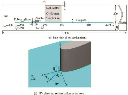
Fig.1 (Color online) Sketches of test section and model arrangement
In addition to the passive controls, a few active approaches were also studied. A spatially-limited, constant-rate suction (ranging from 0% tothrough a slot upstream the cylinder was utilized[14]. The PIV results indicated that the surface suction weakened both the instantaneous turbulent vortex and its associated surface interactions in the symmetry plane, effectively eliminated the average turbulent necklace vortex in the symmetry plane and reduced the average downstream extension of the vortex. Another similar study[15]showed that the suction flow rate ofthrough an opening located in the vicinity of the separation lines, withbeing the diameter of the obstacle andthe displacement thickness of the boundary layer, reduced the vortex size and moved the separation lines towards the obstacle’s leading edge.
According to the above studies, active means seems more effective in turbulent juncture flow control but it is energy consuming for such a high flow rate, even though we could not say exactly where the unsteadiness comes from in a turbulent or laminar junction flow at a Reynolds number larger than 1 000[16]. However, it is indeed really important to junction flow control. In this paper, smoke-wire flow visualizations are conducted in a laminar wing-plate junction to try to find out where the unsteadiness comes from. For a vortex impinging event, a novel active control method is put forward and the control effect is discussed in aspects of mean two-dimensional vector, PDFs, instantaneous streamlines and synchronous fluctuating pressure in turbulent junction flows.
1. Experimental setup
1.1Wind tunnel and test model
Experiments are carried out in a low-speed openreturn wind tunnel with test section dimensions of, as a through type tunnel with an exhaust that recirculates back into the room via a series of filters. A 10 mm thick clear acrylic flat-plate with a 2:1 elliptical leading edge and a sharp trailing edge is mounted horizontally in the test section, 150 mm behind a 7:1 area ratio contraction, with a 200 mm gap between the top wall of the test section and the upper surface of the flat-plate left to install a NACA0020 wing vertically at the centerline. The wing is also made of acrylic, with the chord and the thickness beingand the height being 195 mm to leave a 5 mm gap intentionally between the top wall to prevent the occurrence of junction vortices and their impact on the junction flow of interest. A sketch of the test section and the model arrangement is shown in Fig.1 and the freestream goes from left to right. Figure 1(b) shows a Cartesian coordinatesystem with the origin at the nose of the wing on the flat-plate, marked aspointing in the streamwise direction,vertical to the flat-plate and pointing upwards andnormal to theplane and pointing as in the righthand manner. The planeis a vertical plane at an angle ofto theplane. All the data of laminar or turbulent junction flows presented here are incoordinates and those inare for the detection of the turbulent boundary layers.
1.2Primarily results of PIV measurements
The flow fields around the wing-plate junction are determined with a Dantec dynamics two-dimensional PIV system in theplane. The system consists of a Litron LDY302-PIV 15 mJ per pulse Nd:YLF laser, a Vision Research Phantom V12.1 high-speed camera and a dedicated PC. A SIGMA 105 mm F2.8 DG Macro lens is used. Olive oil seeding particles of nominally 1 μm diameter from a TSI 9307-6 oil droplet generator via a seeding rake[17]are introduced upstream the wind tunnel contraction section. Image pairs are typically taken at a frame rate of 1 000 Hz in a 100 μs interval, and the PIV data are processed using Dantec DynamicStudio v3.41. Velocity vectors are usually computed on apixel grid with 50% (or 75%) overlap indirection, using a recursive cross-correlation technique by 5 refinement steps, corresponding to an interrogation volume of typically 1 024×1 024 for the velocity components, resultingvectors in a full image.
When the freestream velocity, the incoming boundary layer on the flat-plate is tripped by three rows of rubber cylinders (as seen in Fig.1(a)) with a height of 9 mm, based on which the Reynolds number is larger than 900 (referred to Schlichting (1968)), and it ends at 100 mm downstream the flatplate leading edge. Accordingly, the boundary layer flow becomes turbulent from 183 mm downstream the flat-plate leading edge. The tripped boundary layer is detected by the two-dimensional time-resolved PIV system in a vertical centerline plane from 426 mm to 532 mm downstream the leading edge (corresponding tomm to 182 mm in Fig.1(a)), with a growth rate of the boundary layer thickness of 2.2%. The inner normalized mean velocity profile, given in Fig.2, at 430.6 mm downstream the leading edge (i.e.,80.6 mm), is closely matched the logarithmic law in the outer layer and the linear law in the sublayer, whereThe boundary layer thickness takes a value of, hereinAccordingly, the momentum thickness, the displacement thickness5.98 mm and the shape factor. It seems that the tripped boundary layer is a flat-plate turbulent boundary layer flow. The friction velocity based on the logarithmic layer fitting is. Herein,
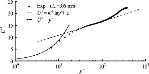
Fig.2 Mean velocity profile of a flat-plate turbulent boundary layer

Fig.3 (Color online) Time-averaged velocity field of turbulent junction flows. (a) Vectors in the symmetric plane in front of a Rood wing at[1], (b) Vectors and streamlines upstream a NACA0020 inplane (to symmetric plane) at
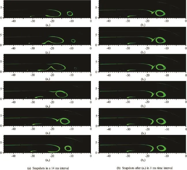
Fig.4 (Color online) Smoke wire flow visualizations inplane of a laminar junction flow (mm)
2. Unsteadiness of turbulent wing-plate junction flows
2.1Statistical unsteadiness
The unsteady “bimodal” nature of the horseshoe vortex “system” has become an interesting research topic, since the bimodal velocity probability phenomenon was firstly reported and believed to be responsible for high surface pressure fluctuation levels and high heat transfer rates in the region[1], using three-velocity-component LDV measurements around the Rood wing at an approaching momentum thickness Reynolds numberof 6 700 in a turbulent junction flow, as reproduced in Fig.3(a). In this figure, one may also observes the elliptical shape of the timeaveraged vortex. Due to the time-dependent characteristics, the flow field in theplane (as shown in the dotted zone in Fig.1(b)) is investigated by the time-resolved PIV at a frame rate of 1 000 Hz in a turbulent wing-plate junction flow in this paper. The time-averaged streamlines and vectors over 4 s are shown in Fig.3(b), as well as a histogram of PDF of longitudinal velocity fluctuations at a location. In the streamline distributions, one sees a line aroundapproaches the wall and rolls up to form a vortical structure, whose centre is located in a place aboutandThe bimodal PDF at the locationshows the statistical unsteadiness of the turbulent wing-plate junction flow, which is in a similar shape as the one in Fig.3(a).
2.2Source of unsteadiness
The unsteadiness of a turbulent wing-plate junction flow is shown by the bimodalfluctuation histogram in Fig.3. To investigate the source of the unsteady vortical motions, smoke-wire flow visualizations of a laminar wing-plate junction flow are conducted in the low speed wind tunnel at a freestream velocity of 1.5 m/s. Two 100 μm diametered smoke wiresare horizontally placed at 55 mm upstream the nose with heights of 4 mm and 9 mm above the wall (as depicted in Fig.1(a)) within the approaching boundary layer, to introduce smoke into the flow with no apparent disturbance. Theplane is illuminated by a pulsed laser sheet and the images of the flow field of interest (as shown in the dotted zone in Fig.1(b)) are taken synchronously at 1 000 Hz, as shown in Fig.4.
The six images on the left (Figs.4(a1)-4(a6)), at an interval of 14 ms, are taken on a cycle of the vortical motions in theplane of a laminar junction flow. Normally, the vortex nearest the nose is called “corner vortex” and the one upstream is called “primary vortex”. It is clearly seen in Figs.4(a1)-4(a4) that both primary and corner vortex are moving downstream and the size of corner vortex is apparently getting smaller as moving closer to the nose, up to a location around. In the meanwhile, the corner vortex is slightly getting closer to the flat-plate in vertical direction, approximately from 2 mm to 1 mm above the flat-plate. Then, the corner vortex changes its direction to go upstream pointing to the primary vortex and merges with the primary vortex to be a new corner vortex of the next cycle, as shown in Figs.4(a4)-4(a6). Additionally, the six adjacent snapshots (Figs.4(b1)-4(b6)) on the right indicate how the vortices evolve within 6 ms after Fig.4(a5). First of all, the corner vortex rotates together with the primary vortex. And then, the shape of the primary vortex is changing while rotating. Finally, the corner vortex merges with the primary vortex and moves downstream together to be a new corner vortex, as shown in Fig.4(b6). Because of the shape change and oscillation, this impinging event is believed to be the source of the unsteadiness of the junction vortex system and pronounced oscillations of their wake flows.
3. Control strategy of turbulent wing-plate junction flows
The flow visualization results clearly depict the vortex impinging event at the base of a laminar junction flow. The vortex motions at the base of a turbulent junction are investigated by time-resolved PIV measurements in theplane and the corresponding instantaneous pressure field is estimated based on the instantaneous vector maps by multi-path integration[18]. Wall pressure in the vicinity of separation is acquired synchronously by a pressure sensor via a 3 mm diametered pressure tab flush mounted on the flat-plate. The snapshots of the pressure contour and streamline in theplane show details how the vortices evolve in a cycle in a turbulent junction flow, as shown in Fig.5. Based on the synchronous fluctuating pressure against time,one sees that the flow is about to separate atandtends to a minus extreme from around a value of zero, then it takes 16 ms forto recover and resume fluctuating around zero (as seen in Fig.5(b)). In the meanwhile, the primary vortex “is moving downstream and a new primary vortexforms and turns the old oneinto a corner vortex at(as seen in Figs.5(a1)-5(a3)). As time passes, the corner vortexstops to move upstream and impinges onto the approaching primary vortex(as seen in Figs.5(a3)-5(a4)). After that, the two vortices merge into one new primary vortexand goes downstream to start the next cycle (as seen in Fig.5(a5)). According to the above description, it seems that a new primary vortex originates in the vicinity of separation and comes into being at. In this process, the vortex pattern of the flow field is alternating[1], followed by impinging event which results in the unsteadiness of the flow field and the pressure fluctuations on the flatplate at the junction corner.
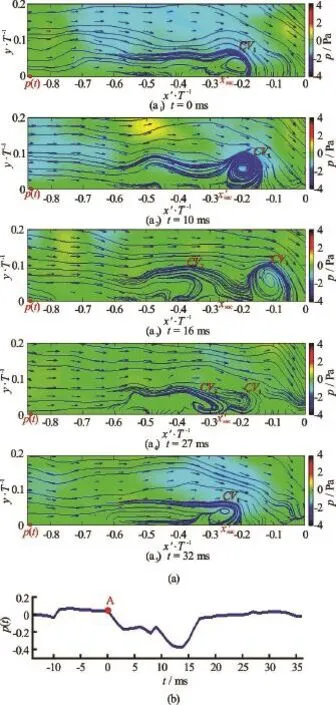
Fig.5 (Color online) Snapshots of streamline and synchronous pressure inplane of a turbulent junction flow
In the process of the horseshoe vortex formation upstream an obstacle, the flow undergoes an adverse pressure gradient upstream the obstacle and starts to distort and roll up around the junction under a strong enough adverse pressure gradient. Many studies of junction flow control[1]tried passive or active means to fight against the adverse pressure gradient. The effects of a classical passive means, a constant radius circular fillet around the base of the Rood wing were examined and it was shown that this modification had the effect of making the wing shape blunter but not preventing the leading edge separation. The bimodal unsteadiness at the nose was not reduced and the size and strength of the vortex legs and the unsteadiness in the wake were not reduced. Recently, a novel passive approach of putting an inclined rod upstream the nose was proposed[19]and both adverse pressure gradient on the flat plate and pressure fluctuations in the vicinity of the cylinder were reduced on the whole. However, the primary horseshoe vortex was still there and pressure fluctuations in the vicinity of the rod were intensified. Besides, some active methods to eliminate the adverse pressure gradient were quite energy consuming[14,15].
The above studies show that it is difficult to eliminate the adverse pressure gradient to prohibit the vortex from coming into being without any significant impact on the flow. The strong enough adverse pressure gradient and separation upstream the obstacle are considered to be inevitable or not easy to do without. However, it might be feasible to stop the vortex formation by the suction where the streamline is about to roll up to form a vortex. And the suction location is determined from the time-averaged velocity field (as seen in Fig.3(b)) in theplane of the turbulent junction flow and marked as(as seen in Figs.3(b) and 5(a)). Here,. To minimize the extra disturbance on the flow field, the suction is implemented via eleven discrete 3 mm diametered straight holes on the flat-plate upstream the wing, which are orifices on a 50 mm diametered circle with its center atin the symmetric plane, as shown in Fig.1(b). They are symmetric fromin ainterval of the 50 mm diametered arc. The suction flow rate,measured by a flowmeter, is normalized by the flow rate within the incoming turbulent boundary,. Namely, the nondimensional suction flow rate is, whereby assuming that the incoming turbulent boundary layer (as shown in Fig.2) is twodimensional andis the width of the horseshoe vortices, which is around the width of the test section. For this experiment,
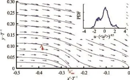
Fig.6 (Color online) Vectors and streamlines inupstream a NACA0020 wing and PDF at0.088)atunder suction control
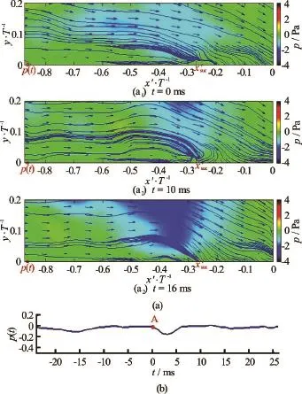
Fig.7 (Color online) Snapshots of streamline and synchronous pressure inplane of a turbulent junction flow under suction control
Table 1 Velocity circulation(m2/s) of turbulent junctions with and without suction

Table 1 Velocity circulation(m2/s) of turbulent junctions with and without suction
4. Results and discussions
The unsteady vortex motion is believed to cause the pressure fluctuation at the base of a junction flow, especially in a turbulent junction flow. As well known, the streamline rolls up and stretches downstream to form a horseshoe vortex upstream the appendage due to the adverse pressure gradient in a laminar or turbulent junction flow (as seen in Fig.4 for the laminar case, Figs.3 and 5 for the turbulent case). Under the suction control as proposed, no evident vortex appears in the averaged flow field in theplane and the flow becomes steady according to the histogram of PDF of longitudinal fluctuating velocity, as shown in Fig.6. Besides, no comparable vortex forms after a relatively weak separation (as seen in Fig.7(b)) in instantaneous flow field under the suction control, as shown in Figs.7(a1)-7(a3). The minus pressure lasts only for 6 ms before recovery in the suction control case, which covers only 37.5% of the temporal length in the case without the control, as shown in Fig.5(b). The peak-valley value and the root mean square value of the fluctuating pressureare reduced by 68.0% and 62.2%, respectively in the suction control case.
The velocity circulation to show the vortex intensity of the flow field is calculated as follows[20]
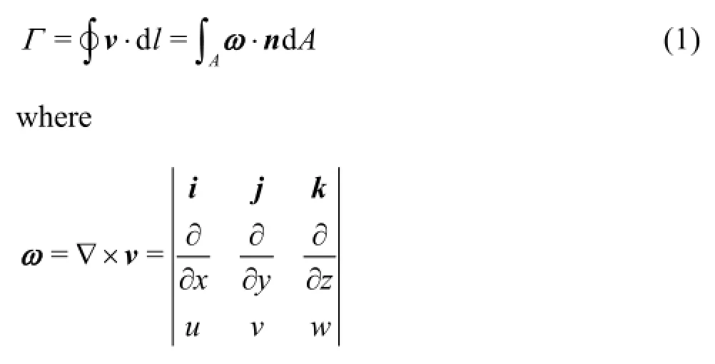
For two-dimensional vectors acquired, i.e.,by the time-resolved PIV,

5. Conclusions
A wing-plate junction flow is experimentally investigated in a low-speed wind tunnel by smoke-wire flow visualizations and two-dimensional time-resolved PIV measurements. Main conclusions are summarized as follows:
According to the time-averaged vectors and streamline distributions in a vertical plane at an angle of 30owith the symmetric plane upstream the nose of the wing in a turbulent junction, the streamlines approach the wall and then roll up to form a vortical structure. Additionally, the bimodal PDF of longitudinal fluctuating velocity is acquired in the flow field. The results indicate that the turbulent wing-plate junction flow is a kind of unsteady and vortical motions.
To trace where the unsteadiness comes from in the turbulent junction flow, smoke-wire flow visualizations are conducted for a laminar wing-plate junction flow. The images captured at 1 000 Hz show a cycle of the vortex motions, during which the corner vortex changes direction to go upstream pointing to the primary vortex and is merged with the primary vortex to be a new corner vortex of the next cycle. This impinging event which leads to a noticeable shape change and significant oscillation of the primary vortex, is believed to be the source of the unsteadiness of the junction vortex system and highly oscillation of the wake flows.
A novel strategy is put forward to prevent the streamlines from rolling up to form a vortex upstream the nose of the wing by the suction at the location where the mean streamlines are about to roll up in the turbulent wing-plate junction flow. And the suction is at a flow rate of 1.2% of that of the approaching turbulent boundary. Under the suction control, no evidentvortex appears in the time-averaged flow field and the Gaussian-like PDF of the longitudinal fluctuating velocity rather than a bimodal one indicates a steady flow. In the suction case, no comparable vortex comes into being in the instantaneous flow fields after a relatively weak separation, whose peak-valley value and the root-mean-square value of the fluctuating pressure are reduced by 68.0% and 62.2%, respectively. The velocity circulations in the suction control case are noticeably smaller than that in the case without the control, especially during the separation when the reduction is more than 12.2%. The maximum reduction, i.e., 24.6%, is achieved when the new primary vortex appears together with the corner vortex. Therefore, the turbulent wing-plate junction flow becomes steady and not evidently a vortical flow by the suction in the vicinity of the separation. Besides, the reduction of the wall pressure fluctuations under the suction makes for the flow radiating acoustic noise reduction at the base of the wing-plate junction flows.
Acknowledgements
The first author would like to express her sincerely gratitude to Professor Kwing Choi-So Choi of the University of Nottingham (UK), where the experiments were carried out. Also, she appreciates China Ship Scientific Research Centre and the China Scholarship Council for the opportunity to conduct the research.
[1] Simpson R. L. Junction flows [J].Annual Review of Fluid Mechanics, 2001, 33(1): 415-443.
[2] Paik J., Escauriaza C., Sotiropoulos F. On the coherent dynamics of turbulent junction flows [J].Physics of Fluids, 2007, 19(1): 045107.
[3] Hinson B. C., Hoffmann K. A. Parametric exploration of wing-body junction flow using computational fluid dynamics [J].Journal of Aircraft, 2015, 52(5): 1492-1509.
[4] Aider J. L., Beaudoin J. F., Wesfreid J. E. Drag and lift reduction of a 3D bluff-body using active vortex generators [J].Experiments in fluids, 2010, 48(5): 771-789.
[5] Doolan C. J., Coombs J. L., Moreau D. J. et al. Prediction of noise from a wing-in-junction flow using computational fluid dynamics [C].Proceedings of Acoustics. Fremantle, Australia, 2012.
[6] Moreau D. J., Doolan C. J. An experimental study of the sound produced by junction flows [C].20th International Congress on Sound and Vibration. Bangkok, Thailand, 2013.
[7] Ostanek J. K., Thole K. A. Flowfield measurements in a single row of low aspect ratio pin fins [J].Journal of Turbomachinery, 2012, 134(5): 051034.
[8] Marakkos K., Turner J. T. Vortex generation in the crossflow around a cylinder attached to an end-wall [J].Optics and Laser Technology, 2006, 38(4): 277-285.
[9] Liu Z. H., Xiong Y., Tu C. X. The method to control the submarine horseshoe vortex by breaking the vortex core [J].Journal of Hydrodynamics, 2014, 26(4): 637-645.
[10] Kirkil G., Constantinescu S. G., Ettema R. Coherent structures in the flow field around a circular cylinder with scour hole [J].Journal of Hydraulic Engineering, ASCE, 2008, 134(5): 572-587.
[11] Devenport W. J., Simpson R. J., Dewitz M. B. et al. Effects of a leading-edge fillet on the flow past an appendagebody junction [J].Journal of American Institute of Aeronautics and Astronautics, 1992, 30(9): 2177-2183.
[12] Kang K. J., Kim T., Song S. J. Strengths of horseshoe vortices around a circular cylinder with an upstream cavity [J].Journal of Mechanical Science and Technology, 2009, 23(7): 1773-1778.
[13] Kairouz K. A., Rahai H. R. Turbulent junction flow with an upstream ribbed surface [J].International Journal of Heat and Fluid Flow, 2005, 26(5): 771-779.
[14] Seal C. V., Smith C. R. The control of turbulent end-wall boundary layers using surface suction [J].Experiments in Fluids, 1999, 27(6): 484-496.
[15] Barberis D., Molton P., Malaterre T. Control of 3D turbulent boundary layer separation caused by a wing-body junction [J].Experimental Thermal and Fluid Science, 1998, 16(1): 54-63.
[16] Kirkil G., Constantinescu G. A numerical study of the laminar necklace vortex system and its effect on the wake for a circular cylinder [J].Physics of Fluids, 2016, 24(7): 073602.
[17] Jukes T. N., Choi K. S. On the formation of streamwise vortices by plasma vortex generators [J].Journal of Fluid Mechanics, 2013, 733(10): 370-393.
[18] Dabiri J. O., Bose S., Gemmell B. J. et al. An algorithm to estimate unsteady and quasi-steady pressure fields from velocity field measurements [J].Journal of Experimental Biology, 2014, 217(3): 331-336.
[19] Wang J. M., Bi W. T., Wei Q. D. Effects of an upstream inclined rod on the circular cylinder-flat plate junction flow [J].Experiments in Fluids, 2009, 46(6): 1093-1104.
[20] Cao N. Z., Chen S. Y., Sreenivasan K. R. Properties of velocity circulation in three-dimensional turbulence [J].Physical Review Letters, 1996, 76(4): 616-619.
(Received November 4, 2015, Revised May 7, 2016)
* Project supported by the National Natural Science Foundation of China (Grant No. 11102188), the National Key Laboratory of Science and Technology on Hydrodynamics.
Biography: Jian-hua Liu (1980-), Female, Ph. D.,
Senior Engineer
 水動(dòng)力學(xué)研究與進(jìn)展 B輯2017年2期
- 水動(dòng)力學(xué)研究與進(jìn)展 B輯的其它文章
- The effects of step inclination and air injection on the water flow in a stepped spillway: A numerical study*
- Modelling of wave transmission through a pneumatic breakwater*
- Comparison of blood rheological models in patient specific cardiovascular system simulations*
- The best hydraulic section of horizontal-bottomed parabolic channel section*
- Numerical simulation of hydrodynamic performance of blade position-variable hydraulic turbine*
- Numerical modelling of supercritical flow in circular conduit bends using SPH method*
