Geometric Design of Anode-Supported Micro-Tubular Solid Oxide Fuel Cells by Multiphysics Simulations
Hong-yu Shi,Jiang Zhu,Zi-jing Lin
Hefei National Laboratory for Physical Sciences at the Microscale and CAS Key Laboratory of Strongly-Coupled Quantum Matter Physics,Department of Physics,University of Science and Technology of China,Hefei 230026,China
Geometric Design of Anode-Supported Micro-Tubular Solid Oxide Fuel Cells by Multiphysics Simulations
Hong-yu Shi,Jiang Zhu,Zi-jing Lin?
Hefei National Laboratory for Physical Sciences at the Microscale and CAS Key Laboratory of Strongly-Coupled Quantum Matter Physics,Department of Physics,University of Science and Technology of China,Hefei 230026,China
High volumetric power density(VPD)is the basis for the commercial success of micro-tubular solid oxide fuel cells(mtSOFCs).To find maximal VPD(MVPD)for anode-supported mt-SOFC(as-mtSOFC),the effects of geometric parameters on VPD are analyzed and the anode thickness,tan,and the cathode length,lca,are identi fied as the key design parameters.Thermo- fluid electrochemical models were built to examine the dependence of the electrical output on the cell parameters.The multiphysics model is validated by reproducing the experimental I-V curves with no adjustable parameters.The optimal lcaand the corresponding MVPDs are then determined by the multiphysics model for 20 combinations of rin,the inner tube radius,and tan.And all these optimization are made at 1073.15 K.The results show that:(i)signi ficant performance improvement may be achieved by geometry optimization,(ii)the seemingly high MVPD of 11 and 14 W/cm3can be easily realized for as-mtSOFC with single-and double-terminal anode current collection,respectively.Moreover,the variation of the area speci fic power density with lca∈(2 mm,40 mm)is determined for three representative(rin,tan)combinations.Besides,it is demonstrated that the current output of mtSOFC with proper geometric parameters is comparable to that of planar SOFC.Key words:I-V relations,Thermal fluid electrochemistry model,Parametric optimization, Volumetric power density,Anode thickness
I.INTRODUCTION
Due to their high electrical efficiency,fuel flexibility and low pollutant emission,solid oxide fuel cells (SOFCs)bear the promise of revolutionizing the fossil fuel based power generation technology[1].For applications in the automotive field and in the auxiliary power supply sector,a new design of SOFC,i.e.,micro-tubular SOFC(mtSOFC)with a tubular diameter typically under a few millimeters,was developed in 1990s[2].Since its inception,mtSOFC has shown drastic improvements over the conventional SOFC designs on thermal shock resistance,fast startup and thermal cycling[3].As a result,mtSOFC is attracting an increased attention in the research and development community[4,5].
High volumetric power density(VPD)is a prerequisite for the commercial success of mtSOFCs in the field of vehicle applications.To meet the requirements in practice,substantial improvements in the designs of cell geometries,stack con figurations,and system operations are required[6].As mtSOFC is a relatively new design and an mtSOFC cell is the basic electricity generating unit,most research efforts are devoted to the fabrication technique for the performance improvement at the cell level.Like the cases for planar SOFCs(pSOFCs),anode supported mtSOFCs(as-mtSOFCs)show higher performance than their electrolyte-and cathode-supported counterparts.Logically,most researchers focused on asmtSOFCs for the performance improvement[7?9].
There are a large number of experimental studies on the performances of mtSOFCs with various choices of materials and geometries[4,10,11]. Compared with conventional SOFCs,there is hardly anything new about the material choices for mtSOFCs,e.g.,YSZ or GDC for the electrolyte,Ni-YSZ or Ni-GDC for the anode,LSCF or LSM for the cathode.However,there are completely new geometric parameters for mtSOFCs, e.g.,the tube diameter and length.Moreover,the anode thickness emerges as an in fluential design parameter as it affects the cell volume and mass that in turn affect the VPD and thermal behavior of mtSOFC.The anode thickness also affects the current collection in most mt-SOFC designs that in turn affects the current output of mtSOFC[4].Furthermore,it has been observed that the cathode location can have substantial in fluence on the output of mtSOFC[11].Clearly,attention should be paid to these new geometric parameters when deve-loping the mtSOFC technology.
There are large differences in the values of anode thickness,tube diameter and cell length of the reported as-mtSOFCs.The anode thickness,though mainly in the range of 200?300μm,varies from 130μm[12]to 2 mm[13].The inner tube diameter is centered around 2 mm,but may vary from 0.8 mm to 22 mm[4].The cell length varies from a few mm to 160 mm[14?16]. The wide variations in the geometric parameters of the manufactured mtSOFCs may be partly attributed to the difference in the fabrication abilities of different groups.More importantly,the phenomenon re flects the fact that there is no good understanding about the correlation between the geometries and cell performance. Improved understanding is necessary for the realization of the best performing mtSOFCs to make their practical applications a reality.As experimental examination is expensive and time consuming,numerical models incorporating the physics of SOFC to predict the performance are invaluable tools for the understanding and development of mtSOFCs.
In this work,the impact of geometric parameters on VPD of as-mtSOFC was examined by performing systematic multiphysics numerical simulations.The multiphysics model considers the intricate interdependency among the ionic and electronic conductions,gas transport,and electrochemical reaction.The model is validated by comparison with experimental results.Simulations with this validated numerical model provide detailed information about the dependence of VPD on geometric parameters.The optimal geometric parameters and the corresponding power output can be used to guide the design and optimization of as-mtSOFCs.
II.THEORETICAL METHOD
A multiphysics model was built and applied to the geometric model of mtSOFC.Simulations of the multiphysics model are carried out to examine the effect of geometric parameters on the cell output.Optimal geometric parameter sets are determined based on the optimization objective as well as practicality considerations.
A.Geometric model and optimization target
A schematic of an as-mtSOFC is shown in FIG.1(a). The mtSOFC consists of a porous anode as the inner layer,a dense electrolyte as the middle layer,and a porous cathode as the outer layer.On the cathode side, the current is collected through the cathode surface.On the anode side,the current is collected through the anode current collector(s)at one or both sides of the anode tube.Due to the axial symmetry of mtSOFC,it is necessary only to apply a two-dimensional(2D)geometric model illustrated in FIG.1(b)for the numericalsimulation.The actual 3D structure of the mtSOFC is obtained by revolving the 2D computational domain around the symmetry axis.

FIG.1 Schematic diagram of mtSOFC.(a)3D structure, (b)2D computational domain.
The goal of multiphysics simulations is to find the geometric parameters that maximize VPD=Pm/Vcell, where Pmand Vcellare respectively the maximum electrical power output and the overall volume of the mt-SOFC cell.Vcellis calculated as,

where lcell,rout,and rinare respectively the length,the outer radius and inner radius of the mtSOFC cell,tan, teland tcaare the thickness of anode,electrolyte and cathode,respectively.The cell length is set as lel+?l, where lelis the length of electrolyte and?l accounts for the required anode current collector,edge sealing,cell connection in a stack,etc.The value of?l is determined by the manufacturing practice.In this work,a value of 6 mm,namely 3 mm for each tube terminal,is used for?l.Such a value for?l is believed to be sufficiently large for practical purpose[3].It is used here also for the purpose of avoiding an overstated maximum VPD (MVPD)achievable by the geometry optimization.
It is reasonable to assume that the current outputis roughly proportional to the area of electrochemically active region,

where lcais the cathode length(FIG.1).For a fixed tube radius,the cathode area is proportional to lca. Therefore,it is trivial to expect that MVPD is obtained with the largest possible lca,i.e.,lca=lel.Though no optimization of lcais necessary,lcaand the cathode position relative to the anode current collector are variable in the geometric model of FIG.1(b)so that the simulation results may be compared with the relevant experiments.
Note that the cell volume increases quadratically with rin,tan,teland tca,while the electrochemically active area increases linearly with rinand tan.This observation calls for as small values of rin,tan,teland tcaas possible for obtaining MVPD.In addition,reducing telalso reduces the ohmic polarization.It is then clear that telshould be as small as possible.However,there is a practical lower limit for teldue to the fabrication technique and the required mechanical strength and gas tightness of the electrolyte layer.Though tel=1μm has been reported[17],telaround 5μm is more manageable in practice[18].Therefore,a default value of 5μm is assigned to tel,unless explicitly stated otherwise.Similarly,rincannot be too small due to the fuel supply requirement and the limitation of the fabrication technique.Reducing tcais also bene ficial for the cell performance as long as the cathode layer is adequately thick to accommodate the electrochemical reaction region that is known to be around 10μm for the widely used cathode materials[19].Consequently,tca=10μm is used in this work.
Unlike the cases with teland tca,reducing tanis detrimental to the anode current collection by reducing the cross section of current passage for the anode current collection method shown in FIG.1.There should be an optimal balance between the needs of reducing tanfor the reduced Vcelland increasing tanfor the reduction of ohmic polarization.It is noted that the relationship between tanand the current conducting cross section is dependent on the method used for the anode current collection.However,the anode current collection shown in FIG.1 is widely used for its technical simplicity[3,4] and is the focus of this study.
A related but different consideration is required for the geometric parameter lel=lca.Notice that both the cell volume and the current producing area increase linearly with lel=lca.Increasing lel=lcaincreases the fraction of the current producing area on the cell surface and is bene ficial for VPD.However,there is a limit on the total cell current due to the ohmic loss of anode current collection.The cell current production is in fact expected to increase less than linearly with lel.As a result,there is an optimal value of lel=lcathat yields MVPD.
Based on the above analysis,there are basically two optimizing parameters,lcaand tan,for given rinas well as?l that are set by practical fabrication considerations.Moreover,the anode layer cannot be too thin in an as-mtSOFC.That is,the choice of tanis in fact not arbitrary.Therefore,this work focuses on finding the optimal lcell=lca+?l for a set of practical combinations of rinand tan.Nevertheless,the optimal tanfor a given rinis also examined.
B.Thermal fluid electrochemistry multiphysics model
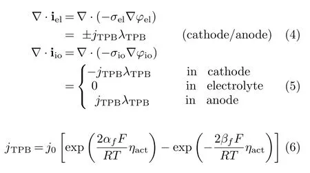
A standard set of governing equations for the currentvoltage(I-V)relation,mass and momentum transports are applied.The multiphysics equations and the associated source terms used are shown as follows.
For I-V relation:

For charge transport:
For mass transport[20]:
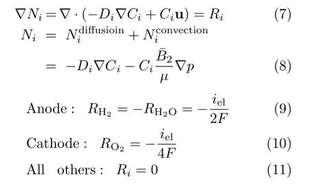
For momentum transport:
(i)fuel channel,

(ii)porous electrode,

Most variables and parameters mentioned in Eq.(3)?Eq.(13)are self explanatory.Details about the governing equations and their source terms,boundary conditions,numerical grids and solver,basic parameters for physical properties of materials and cell operating conditions,etc.,are referred to Ref.[7].The multiphysics model has been shown to provide I-V curves that are in very good agreement with the experimental results for both pSOFC and mtSOFC consisting of Ni-YSZ anode/YSZ electrolyte/LSM-YSZ cathode[7,10,21,22].
Although the multiphysics model employs a set of governing equations that are quite general,the numerical results are dependent on the values of model parameters.To avoid using a large number of variable material parameters,only the material combination of Ni-YSZ anode/YSZ electrolyte/LSM-YSZ cathode with parameters described in Ref.[7]is considered here.Notice that this is not a limitation as it appears to be. Instead,the optimization results are in fact quite general. This is because that,as discussed above,the thicknesses of electrolyte and cathode are not the true geometric optimization targets.The optimal cell and electrolyte/cathode lengths are closely related to the electronic conductivity of the anode.Considering the fact that Ni is currently a universal material choice for SOFC anodes,the anode electronic conductivity is determined by the Ni content.Consequently,the Ni-YSZ based optimization results are of broad implications as they are valid also for other Ni based anode materials, e.g.,Ni-GDC,Ni-SDC,Ni-CGO,etc.
III.RESULTS AND DISCUSSION
A.Dependence of cell performance on the cathode location
The in fluence of the cathode location on the cell performance has been examined experimentally by comparing the electrochemical performances of four single cells[11].The four single cells composed of Ni-YSZ anode/YSZ electrolyte/LSM-YSZ cathode were essentially identical,but differed in the distance,d,between the cathode and the anode current collector.The four single cells,cell A,cell B,cell C and cell D,correspond to d=2,5,8 and 14 cm,respectively.Geometric models were built to correspond to the speci fications of the four single cells and the same set of property parameters as described in Ref.[7]was applied for the multiphysics simulations.The parameter set of Ref.[7]have been shown to reproduce the experimental results of Ref.[10]very well.With this set of parameters,the theoretical I-V curves for the four single cells are shown together with the experimental data in FIG.2.As seen in FIG.2,the theoretical and experimental results are in very good agreement.The result is remarkable as the values of all the model parameters are exactly the same as that in Ref.[7]and there is no fitting parameter used in this study.The ability to reproduce two independent experiments[10,11]with the same set of parameters demonstrates convincingly the predictive power of the multiphysics model employed here.
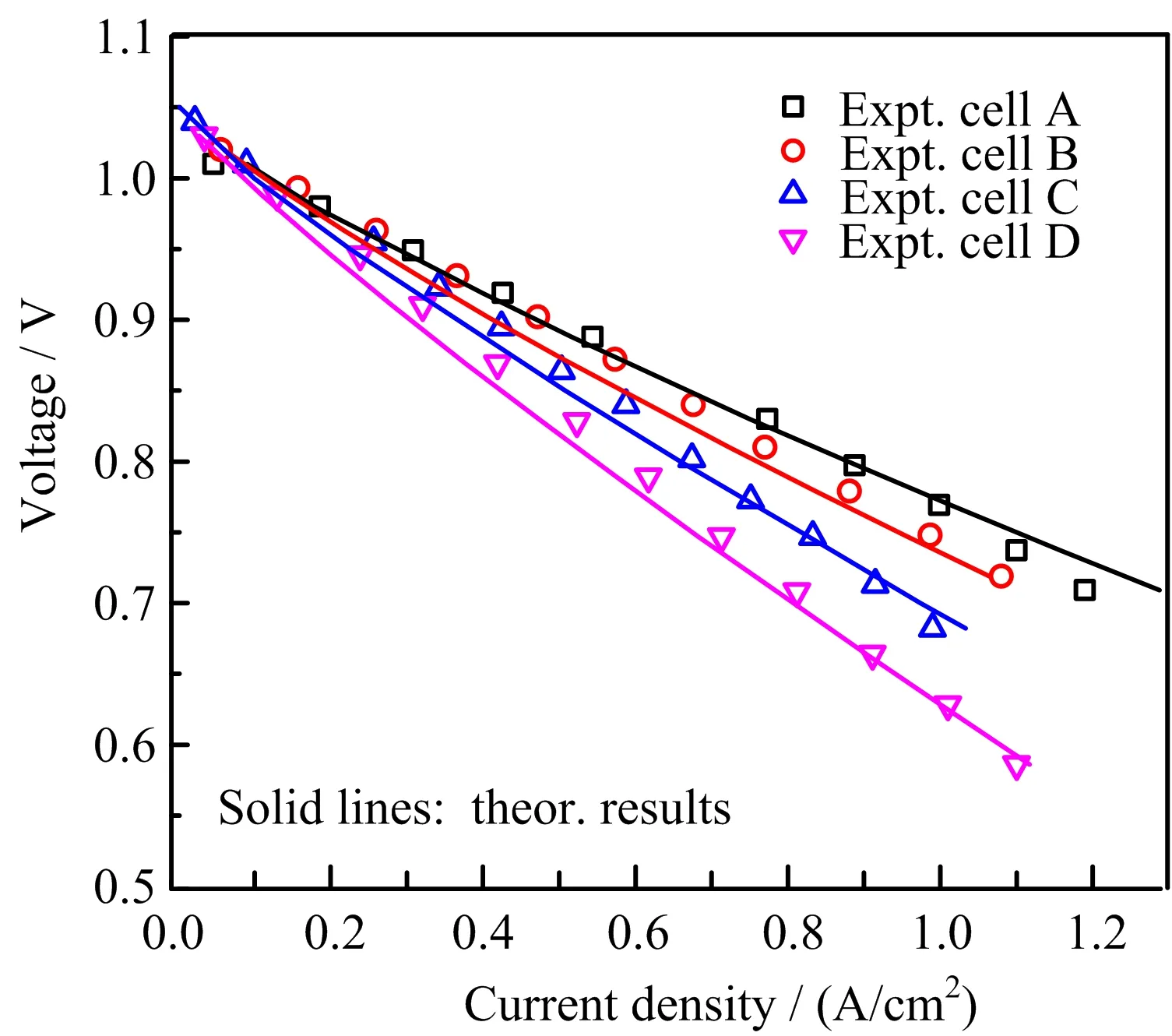
FIG.2 Comparison of the theoretical and experimental I-V curves of four single cells A,B,C,D that differ in the distance d between the cathode and the anode current collector with d=2,5,8,14 cm,respectively.
The decreased cell performance with the increased d shown in FIG.2 is simply due to the associated increase of the ohmic loss of current collection.The current is collected by traveling a distance of d and passing through a cross section area:

For the above four single cells,tan≈rin≈1.5 mm[11] and Aanis relatively large at about 20 mm2.For such a large Aan,the decrease in the cell performance is already noticeable for a distance of a few centimeters,as shown in FIG.2.For a typical mtSOFC with Aan≈1 mm2[4],a cell performance decrease is therefore expected to be substantial for an increase of d in the order of a few millimeters.As a result,the bene fit of increasing lcafor the cell current production quickly diminishes while the rate of cell volume increase remains constant. Therefore, finding an optimal lcathat maximizes VPD is important in practice.
B.Optimal cell length with single-terminal anode current collection
Multiphysics simulations were performed for 20 combinations of(rin,tan),with rin=(0.4,0.85,1.5,3.0, 5.0 mm)and tan=(100,200,300,500μm).The ranges of rinand tanare chosen to cover the ranges of tube radius and anode thickness of known mtSOFCs that use anode tube terminal current collection[4].lcais varied for the search of MVPD.The optimal lcaand the corresponding MVPD for each of the 20 combinations of (rin,tan)are shown in Table I.

TABLE I Cell lengths that maximize VPD at T=1073.15 K for different combinations of anode thickness,tan,and inner tube radius,rin.The cell uses a single-terminal anode current collector and lcell=lca+6 mm.lcais in mm and MVPD in W/cm3.
As seen in Table I,the optimal cell length,or the corresponding lca,is mainly determined by tanand weakly dependent on rin.On one hand,as can be seen in Eq.(2) and Eq.(14),for a given rin,an increase of tan,?tan, causes a relative increase of Aanby

and a relative increase of AECby

Due to the extra capacity of current conduction provided by the larger increase of Aan,lcaincreases with tan,as shown in Table I.On the other hand,for a given tan,an increase of rin,?rin,corresponds to

Thatis, ?Aan/Aanisonly slightly largerthan?AEC/AEC.As a result,there is only a small increase of lcafor the increase of rin.
The optimal tanfor a given rin,in terms of yielding the highest MVPD,is also shown together with the optimized lcaand MVPD in Table I.As expected and discussed above,Table I shows that MVPD increases with the reduced rin.A small rinmeans a small AECand does not require a large current conducting capacity.Meanwhile,an increase of tancorresponds to a large relative change in Vcell.As a result,the optimal tanfor finding MVPD is small for a small rin,as seen in Table I.
It should be noticed that the data in Table I are obtained with a set of conventional and mature materials,i.e.,Ni-YSZ anode/YSZ electrolyte/LSM-YSZ cathode.A thickness of 5μm assumed for the electrolyte layer should also impose no signi ficant challenge on fabrication technique[4,17,18].The tube outer diameter for practical mtSOFCs is often under 2 mm [4].Such a tube is about the size of the tube with rin=850μm and tan=150?200μm.Moreover,an ample room,?l=6 mm of the tube length,has been allocated for the current collection and stack assembly[23]. Therefore,it may be concluded that the seemingly high MVPD=11 W/cm3for rin=0.85 mm is not only achievable,but also surpassable in practice.
As the practical lcamay not be optimal due to various considerations,FIG.3 shows the dependence of the maximum area speci fic power density,pm=Pm/AEC, on lcafor three combinations of(rin,tan):(0.4 mm, 100μm),(0.85 mm,200μm),(1.5 mm,300μm). The three(rin,tan)combinations are representative as rin∈(0.4 mm,1.5 mm)and tan∈(100μm,300μm)are reported for most mtSOFCs[4].For other practically chosen(rin,tan)with rinand tanin the above stated range,pmmay be estimated by suitable interpolation. Together with?l required in practice,VPD can then be predicted and used to help the design of mtSOFC. As a special case of practical interest,FIG.3 shows that pm≈0.9 W/cm2may be expected for as-mtSOFC with (rin=0.85 mm,tan=200μm,lca=10 mm).
C.Optimal cell length with double-terminal anode current collection
Similar to the cases with single-terminal anode current collection(STACC),multiphysics simulations were performed for mtSOFCs with double-terminal anode current collection(DTACC).The results for the optimal lcaand MVPD are shown in Table II.Due to the same reason analyzed above,the results shown in Table II and Table I are qualitatively the same concerning:(i)lcaincreases with the increase of tanmuch more than with the increase of rin.(ii)MVPD decreases while the optimal tanincreases with the increase of rin.Moreover,it is natural to see that lcaand MVPD are larger for DTACC than for STACC. Though the length of current pathway is cut by half from STACC to DTACC,lca(DTACC)is less than 2lca(STACC)for MVPD as pmdecreases with lca,as shown in FIG.3.As a result,lca(DTACC)is about 60%larger than lca(STACC)for finding MVPD.It is noted in Table I that lca(DTACC)/lca(STACC)is fairly constant,whereas MVPD(DTACC)/MVPD(STACC) shows a little more variation and decreases with the increased lca. Nevertheless,it is a good approximations to say that MVPD(DTACC)is 30%higherthan MVPD(STACC).For the practical combination of(rin≈0.85 mm,tan≈150μm),an MVPD of over 15 W/cm3may be expected with DTACC.

TABLE II Cell lengths that maximize VPD at T=1073.15 K for different combinations of(rin,tan).The cell uses a double-terminal anode current collector and lcell=lca+6 mm.lcais in mm and MVPD in W/cm3.
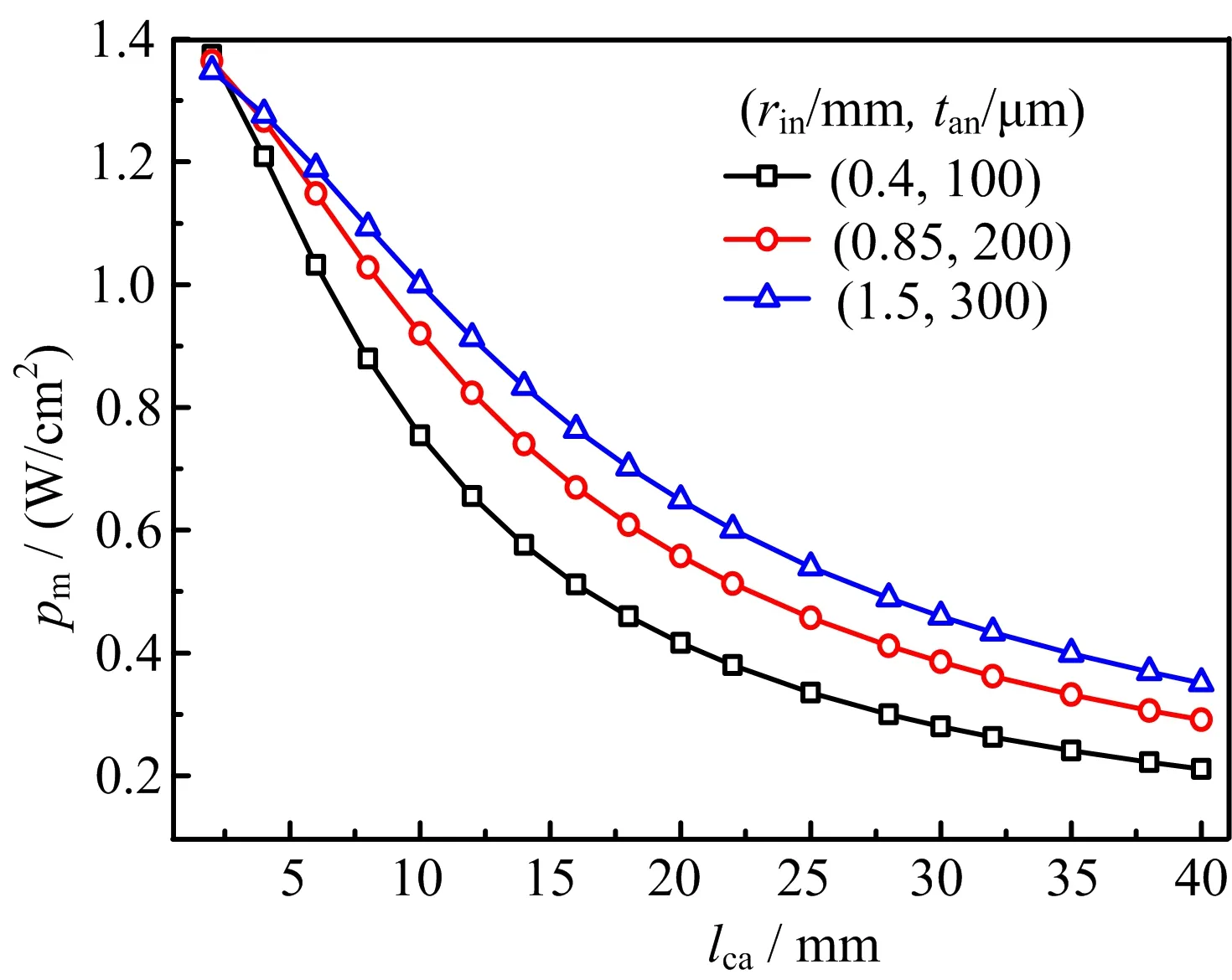
FIG.3The maximum area speci fic power density,pm, by single-terminal anode current collection(STACC)vs. the cathode length,lca,for(rin,tan)=(0.4 mm,100μm), (0.85 mm,200μm)and(1.5 mm,300μm).
To provide more information about the performance of mtSOFC versus the tube size,FIG.4 shows the dependence of pmon lcafor the three combinations of(rin, tan):(0.4 mm,100μm),(0.85 mm,200μm),(1.5 mm, 300μm).Comparison of FIG.3 and 4 shows clearly that pmis higher for DTACC than for STACC.Notice that theoretically pmfor DTACC is the same as pmfor STACC when lcaapproaches zero.The improvement on pmwith DTACC is attributed to the fact that the length of current conducting path and the amount of current collected by each collector are both cut by half in comparison with that in STACC. The ohmic loss with DTACC is reduced by the shortened conducting path and the reduced current amount. As both the conducting path and the total current increase with lca,the ohmic loss reduction increases with the increased lca.Consequently,the improvement on pmwith DTACC increases with the increased lca. Similarly,pmwith DTACC deceases slower than that with STACC for the increased lca,as shown in FIG. 3 and 4.Increasing lcafor the increased pmis more meaningful with DTACC than with STACC.Though STACC may be convenient and is the main method in use,the effort of developing DTACC technique is worthwhile for reasonably large lca,say,6 mm or more. For(rin=0.85 mm,tan=200μm,lca=10 mm),pmis increased from 0.9 W/cm2for STACC to 1.2 W/cm2for DTACC.
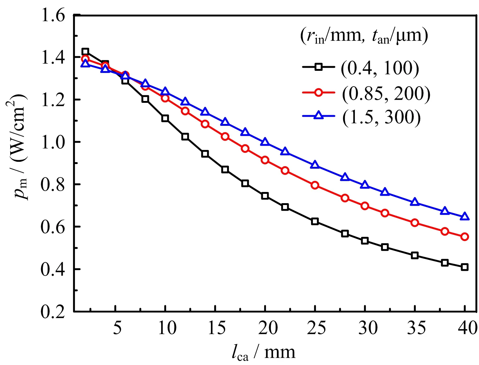
FIG.4 pmby double-terminal anode current collection (DTACC)vs. lcafor(rin,tan)=(0.4 mm,100μm), (0.85 mm,200μm)and(1.5 mm,300μm).
D.Primitive comparison of the performances of mtSOFC and pSOFC
It is a common perception that mtSOFC is advantageous on thermal shock resistance and fast startup as well as thermal cycling,but suffers from the drawback of much lower current output than that of pSOFC.As shown above,however,the cell current production can be substantially improved by the geometric optimization and by using DTACC instead of the conventional STACC.In fact,FIG.4 indicates that the performance of mtSOFC can be comparable with that of the state of the art pSOFC[21].It should be interesting to compare the performances of mtSOFC and pSOFC.However,a quality comparison should examine the effect of a number of key design parameters and require a dedicated effort of study.Consequently,only a preliminary comparison is made here.
As the experimental results reported in Ref.[21]are representative of the best performing pSOFC,the same set of materials and relevant geometric parameters are used for mtSOFC.In addition,the practical parametersof(rin=0.85 mm,tan=200μm,lca=10 mm)are assigned for the mtSOFC.FIG.5 compares the I-V curves and power densities of the theoretical mtSOFC and experimental pSOFC cells.
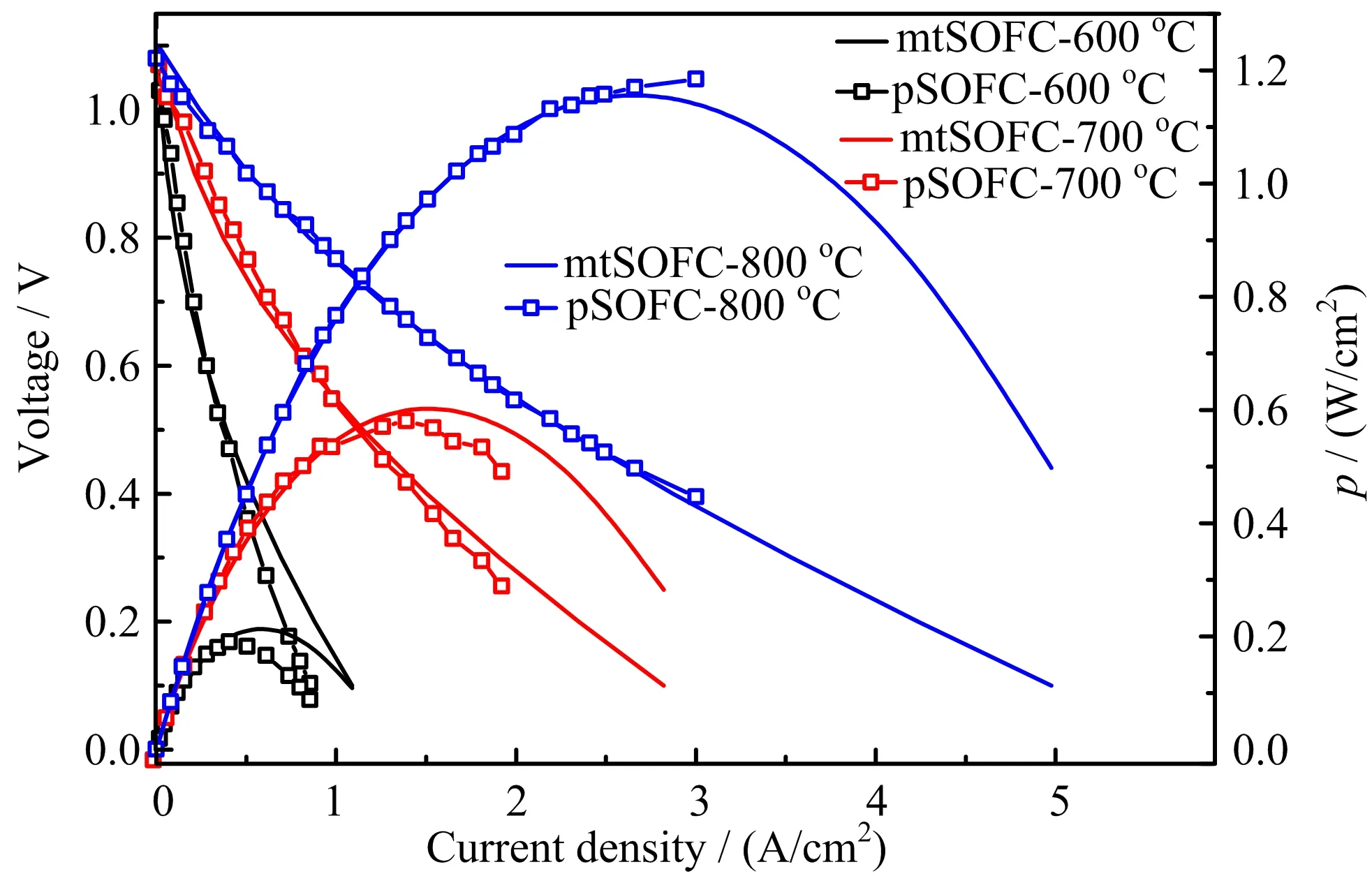
FIG.5 Comparison of I-V and I-p relations of mtSOFC and pSOFC(p:area speci fic power density).
As shown in FIG.5,the power output of mtSOFC is in fact quite comparable to its pSOFC counterpart. This is understandable as the material properties of the two cells are similar and the extra ohmic loss in mt-SOFC with lca=10 mm and tan=200μm is quite limited(FIG.4).That is,with proper selections of geometric parameters,the electrochemical performance of mtSOFCs can be sufficiently high and very close to that of pSOFCs.The observed phenomenon that the current output of mtSOFC is much lower than that of pSOFC is caused by immature fabrication technique and poor choice of geometric parameters.In other words,the common perception that the current output of mtSOFC is much lower than that of pSOFC is inaccurate and misguided.
IV.CONCLUSION
Based on this study,the following results are obtained.(i)rin,tanand lcaare the main geometric parameters affecting VPD of as-mtSOFC.(ii)The multiphysics model employed is capable of reproducing experimental I-V curves with no adjustable parameters. (iii)The optimal values of lcaand the corresponding MVPDs are found for 20 combinations of(rin,tan)with five representative rinand four representative tan.(iv) The variation of pmwith lca∈(2 mm,40 mm)is determined for three representative combinations of(rin, tan).(v)The electrochemical performances of mtSOFC and pSOFC are comparable.
The numerical results show that:(i)for(rin=850μm, tan=200 μm) representative ofthe practicalasmtSOFCs and T=800?C,the seemingly high MVPD of 11 and 14 W/cm3can be easily realized for STACC and DTACC,respectively;(ii)considering the practical lcaof about 1 cm,it is realistic to expect pmof about 0.9 and 1.2 W/cm2for as-mtSOFC with STACC and DTACC,respectively;(iii)signi ficant performance improvement may be achieved by geometry optimization. The performance of optimized as-mtSOFC is comparable to that of pSOFC.Based on these numerical results, it is concluded that mtSOFC is a promising technology for vehicle applications.
V.ACKNOWLEDGMENTS
This work was supported by the National Natural Science Foundation of China(No.11374272 and No.11574284)and the Collaborative Innovation Center of Suzhou Nano Science and Technology.
[1]T.Suzuki,Z.Hasan,Y.Funahashi,T.Yamaguchi,Y. Fujishiro,and M.Awano,Science 325,852(2009).
[2]K.K.T.Alston,M.Palin,M.Prica,and P.Windibank, J.Power Sources 71,271(1998).
[3]V.Lawlor,S.Griesser,G.Buchinger,A.G.Olabi,S. Cordiner,and D.Meissner,J.Power Sources 193,387 (2009).
[4]V.Lawlor,J.Power Sources 240,421(2013).
[5]J.Li and Z.Lin,Int.J.Hydrogen Energ.37,12925 (2012).
[6]A.Li,C.Song,and Z.Lin,Appl.Energ.190,1234 (2017).
[7]J.Li,W.Kong,and Z.Lin,J.Power Sources 232,106 (2013).
[8]B.X.Wang,Z.Jiang,and Z.J.Lin,Chin.J.Chem. Phys.28,299(2015).
[9]K.S.Howe,G.J.Thompson,and K.Kendall,J.Power Sources 196,1677(2011).
[10]C.Yang,W.Li,S.Zhang,L.Bi,R.Peng,C.Chen,and W.Liu,J.Power Sources 187,90(2009).
[11]C.Jin,J.Liu,L.Li,and Y.Bai,J.Membrane Sci.341, 233(2009).
[12]T.Suzuki,Y.Funahashi,T.Yamaguchi,Y.Fujishiro, and M.Awano,Solid State Ionics 180,546(2009).
[13]A.Mirahmadi and K.Vale fi,Ionics 17,767(2011).
[14]Y.Funahashi,T.Shimamori,T.Suzuki,Y.Fujishiro, and M.Awano,J.Power Sources 163,731(2007).
[15]A.Li and Z.Lin,Chin.J.Chem.Phys.30,139(2017).
[16]S.B.Lee,K.i.S.Yun,T.H.Lim,R.H.Song,and D. R.Shin,ECS Transactions 7,187(2007).
[17]T.Suzuki,M.H.Zahir,T.Yamaguchi,Y.Fujishiro,M. Awano,and N.Sammes,J.Power Sources 195,7825 (2010).
[18]S.Lee,T.Lim,R.Song,D.Shin,and S.Dong,Int.J. Hydrogen Energ.33,2330(2008).
[19]D.Chen,W.Bi,W.Kong,and Z.Lin,J.Power Sources 195,6598(2010).
[20]W.Kong,H.Zhu,Z.Fei,and Z.Lin,J.Power Sources 206,171(2012).
[21]F.Zhao and A.Virkar,J.Power Sources 141,79(2005).
[22]W.Kong,J.Li,S.Liu,and Z.Lin,J.Power Sources 204,106(2012).
[23]N.M.Sammes,Y.Du,and R.Bove,J.Power Sources 145,428(2005).
ceived on April 14,2017;Accepted on May 19,2017)
?Author to whom correspondence should be addressed. E-mail:zjlin@ustc.edu.cn,Tel.:+86-551-63606345,FAX:+86-551-63606348
 CHINESE JOURNAL OF CHEMICAL PHYSICS2017年4期
- CHINESE JOURNAL OF CHEMICAL PHYSICS的其它文章
- Laser-Assisted Stark Deceleration of Polar Molecules HC2n+1N(n=2,3,4) in High-Field-Seeking State
- Fabricating Core-Shell WC@C/Pt Structures and its Enhanced Performance for Methanol Electrooxidation
- γ-Ray Irradiation-Derived MnO/rGO Composites for High Performance Lithium Ion Batteries
- Highly Responsive and Selective Ethanol Gas Sensor Based on Co3O4-Modi fied SnO2Nano fibers
- Binding Mechanism and Molecular Design of Benzimidazole/Benzothiazole Derivatives as Potent Abl T315I Mutant Inhibitors
- Identi fication of Superoxide O2?during Thermal Decomposition of Molten KNO3-NaNO2-NaNO3Salt by Electron Paramagnetic Resonance and UV-Vis Absorption Spectroscopy
