A New Quantum Gray-Scale Image Encoding Scheme?
Mosayeb Naseri,Mona Abdolmaleky,Fariborz Parandin,Negin Fatahi,Ahmed Farouk,and Reza Nazari
1Department of Physics,Kermanshah Branch,Islamic Azad University,Kermanshah,Iran
2Department of Electrical Engineering,College of Engineering,Kermanshah Branch,Islamic Azad University,Kermanshah,Iran
3Computer Sciences Department,Faculty of Computers and Information,Mansoura University,Egypt
4Department of IT Engineering,College of Engineering,Kermanshah Branch,Islamic Azad University,Kermanshah,Iran
1 Introduction
The pioneering work of Bennett and Brassard has been developed for the purpose of understanding quantum cryptography,which is one of the most signi fi cant aspects of the laws of the quantum mechanics.[1]Afterwards,the improvement and growth of real applications in different fields of quantum computation and quantum information has been proposed in Refs.[2–20].One of the most growing fields is quantum information data hiding,which includes quantum watermarking and quantum steganography.different quantum information data hiding techniques to protect information were proposed in Refs.[21–30].
In Ref.[21]a novel quantum steganography protocol was based on quantum secure direct communication to build up hidden channel within the improved ping-pong protocol to transmit secret messages.Quantum steganography with noisy quantum channels for hiding quantum information by disguising it as noise in a code word of a quantum error-correcting code was presented in Ref.[22].In Ref.[23]a secure quantum watermarking used entanglement swapping to build up a hidden layer of secure message under the conventional first layer of secure information sequence.A robust watermark strategy for quantum images based on quantum fourier transform as the watermark image is embedded into the fourier coefficients of the quantum carrier image,which will not affect the carrier image’s visual effect was discussed in Ref.[24].A novel dynamic watermarking scheme for quantum images based on Hadamard transform was proposed in Ref.[25].A novel multi-party quantum steganography protocol based on quantum secret sharing as Hidden channels are built in HBB and improved HBB quantum secret sharing protocols for secret messages transmitting,via the entanglement swapping of GHZ states and Bell measurement was presented in Ref.[26].In Ref.[27]two blind LSB steganography algorithms in the form of quantum circuits based on the novel enhanced quantum representation(NEQR)for quantum images were proposed.In Ref.[28]a new quantum gray-scale image watermarking scheme by using simple and small-scale quantum circuits where NEQR representation for quantum images was used.Hilbert image scrambling algorithm,which is commonly used in classical image processing,is carried out in quantum computer by giving the scrambling quantum circuits was proposed in Ref.[29].High-efficiency quantum steganography based on the tensor product of Bell states as a hidden channel is established to transfer a secret message within any quantum secure direct communication(QSDC)scheme that is based on 2-level quantum states and unitary transformations was presented in Ref.[30]. In Ref.[31],a new scheme for quantum watermarking based on quantum wavelet transform is proposed which includes scrambling,embedding and extracting procedures.In this paper,a new scheme for encoding the quantum images is proposed.The proposed scheme can be applied by four different encoding algorithms.The proposed scheme is working as follow; firstly,for each pixel of an initial image,a binary key is generated randomly.Secondly,according to the corresponding qubit pair of the generated randomized binary key,an appropriate encoding algorithm is selected.The security of the proposed protocol is assured by both the randomization of binary image key and the alteration of the gray-scale value of the original image’s pixels using the randomized binary key.This article is organized as:in Sec.2,the required preliminaries to implement the protocol are introduced.In Sec.3,the proposed protocol is presented.In Sec.4 the applicability and the efficiency of the proposed scheme are evaluated by software simulation.Finally,Sec.5 concludes the paper.
2 Preliminaries
2.1 Quantum Gate
In quantum computation schemes,quantum gates can be considered as basic quantum circuits operating on a small number of qubits,i.e.,they are the building blocks of quantum circuits.
To implement the proposed scheme,three quantum gates are mainly employed:
(i)Quantum NOT Gate:A quantum NOT operator,which is also named as PauliXmatrix,acts on a single qubit.It is the quantum equivalent of the NOT Gate in classical logic.It maps|0>to|1>and|1>to|0>.
(ii)Quantum Controlled Not Gate(Quantum CNOT gate):A simple quantum CNOT operator(or a quantum controlled NOT)acts on two qubits,and performs the NOT operation on the second qubit only when the first qubit is|1>.Otherwise nothing happens.This gate is the quantum equivalent of the XOR gate in classical logic.
(iii)Quantum SWAP Gate:A quantum SWAP gate acts on two qubits and swaps them.
The circuit diagram and matrix form representation of these gates are shown in Fig.1.

Fig.1 The circuit diagram and matrix form representation of quantum NOT,CNOT and SWAP gates.
2.2 Quantum Image Representation
A number of quantum representation models for digital images have been presented in the recent years.A common used quantum representation of digital images named as flexible representation of quantum images(FRQI)was presented in Ref.[20].As mentioned in the introduction,a very famous quantum representation for digital images named as a novel enhanced quantum representation(NEQR)for quantum images was proposed in 2013.[21]In the(NEQR)model,two entangled qubit sequences are used to store the gray-scale value and position information of the all pixels of an image.
A representation of a 2N×2Nimage with a gray-scale range of 2qby using NEQR model is defined as follows:

A simple example of a 2×2 quantum image using NEQR model and its quantum representation is shown in Fig.2.

Fig.2 A simple example of image representation using NEQR model.[18]
Using an improved version of NEQR model,a representation of a 2M×2Nimage with the gray-scale range of 2qis as follows:

3 Previous Works
3.1 Quantum Image Gray-Code and Bit-Plane Scrambling
A quantum image gray-code and bit-plane scrambling algorithm was proposed by Zhouet al.in 2015.[32]The proposed algorithm for quantum image gray-code and bitplane scrambling is based on encoding the gray-scale value of the pixels,where for the aim of scrambling,8 binary bit-planes are built from the original image.Thek-th bitplane(1≤k≤8)is formed by thek-th bits of gray-scale value of all pixels of the image.Then,according to the Gray-code scheme,XOR operators are applied on all of these bit-planes.At last,using a reverse procedure,a new scrambled image is generated by the encoded bit-planes.
Needless to say,by using this method,the gray-scale values of original image’s pixels are changed seriously.
This scheme is formulated as follows:

wheret=(M+N)/2,Scr denotes the scrambling,g(y,x)is the gray-scale value of the output pixels of the scrambling process and?denotes the tensor product.
3.2 Quantum Hilbert Image Scrambling Algorithm
The Hilbert Image Scrambling Algorithm is commonly used in the classical image processing.A quantum version of the Hilbert Image Scrambling Algorithm was proposed by Jianget al.,in 2014.[27]In this algorithm,as the first step,a modified recursive generation algorithm of Hilbert scanning matrix is given.Then based on the flexible representation of quantum images(FRQI),the Hilbert scrambling quantum circuits,which are recursive and progressively layered,are proposed.
This scrambling method encodes a 2N×2Noriginal image,which can be considered as a matrix,called the Start matrix(or the Original matrix)Snand use 1 to 22nto code all the pixels.By using the start matrix a Hilbert scanning matrix(Hn)is generated,which is formed by Hilbert curve and is defined as a permutation of the start matrix.Using the Hilbert matrix,the Hilbert curve and the scrambled image can be obtained.
Considering the Hilbert curve and the geometric transportation(Fig.3),the original image will be encoded.In this method no change appears in the gray-scale value of the pixels,concluding,the histogram diagrams of the original and encoded images are the same.
There are two main weaknesses in this scheme:First,since the Hilbert curve and Hilbert scanning matrixHnare only determined byn,the same geometric transportation is used for any 2N×2Nimage.Therefore,by capturing the Hilbert scanning matrix,an attacker can simply decrypt the encoded image and retrieve the original one.Second,since the Hilbert scanning matrix is a square matrix,the algorithm can only be used to encode a square image.

Fig.3 Hilbert curves and a scrambling example.
4 Proposed Algorithm
In this section,our new algorithm for quantum image encoding is presented.In this algorithm a random binary image is used to increase the security of the protocol.In order to encoding image,according to the corresponding qubits of the key,one of the four different encoding schemes is employed to change the gray-scale value of the pixels.It is worth to pointing out that the employed key image is not only used in selecting the suitable scheme,but also it is used directly in the scrambling scheme,which enhances the security of the proposed method,and by having this binary key image the encoded image can be simply decoded.
By using the improved NEQR representation of quantum images,the proposed algorithm can be summarized in the following simple formula:

wheret=(M+N)/2,Scr denotes the encoding task,f′(y,x)is the gray-scale value of theyxpixel of the encoded image and?denotes the tensor product.A simple schematic diagram of the proposed scheme is represented in Fig.4.
In which,for the aim of encoding a 2N×2Msized quantum image,a random binary key image is generated,i.e.,a 2N×2Msized quantum binary image with random values for each pixel is generated by the encoder(say Alice).
By using the improved NEQR representation of quantum images,the random binary key image is formulated as follows:

wheret=(M+N)/2,RBK denotes the Random Binary Key and,1 is the binary value of the(y,x)pixel.Then she stores the random binary key image that is used in the encoding and decoding processes,which are as follows:
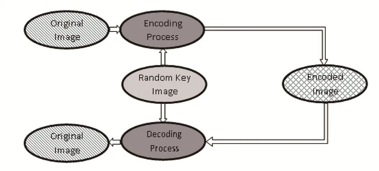
Fig.4 Schematic of proposed algorithm.
4.1 Encoding Process
Step 1Selecting the encoding algorithm based on the random binary key:
At first,based on the random binary key image qubits,Alice selects the encoding algorithm for every pixel.Suppose that,she wants to encode thePijpixel.According to the value ofin whichusing the rule described in Table 1,one of the four encoding algorithms is selected.
For more clarity,a simple example is given in Fig.5.As seen in Fig.5,since the binary values of the(1,1)andpixels of the key image are,Alice will apply the encoding algorithm B on(1,1)pixel of the original image.
The quantum circuit of the key qubits and selected encoding algorithm is shown in Fig.6.
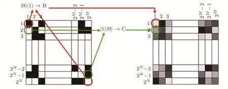
Fig.5 Corresponding qubits of the binary key imageand the selected encoding algorithm.
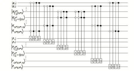
Fig.6 Quantum circuit of key qubits and selected encoding algorithm.

Table 1 Qubits of the key and corresponding encoding algorithm.
Step 2Applying the corresponding encoding algorithm on pixels:
After selecting the encoding algorithm based on corresponding qubits of the key image,one of the A,B,C or D encoding algorithms is applied on the corresponding pixel of the original image.These four encoding algorithms can be described as follows:
Algorithm AThis algorithm swaps theandqubits of the gray-scale value of an input pixel withqubits of its gray-scale value respectively.Then it applies NOT gates on the
Algorithm BThis algorithm swaps thequbits of gray-scale value of an input pixel withqubits of its gray-scale value respectively.Then it applies NOT gates on
Algorithm CAlgorithm C swaps thequbits of the gray-scale value of an input pixel withqubits of its gray-scale value respectively.Then to encode the value of qubit
(i)Ifcis an odd number,an NOT gate is applied on the qubit
ii Ifcis an even number,an XOR gate is applied on the qubitand the qubitof the key image,and the resulted value is copied to
Algorithm DThis algorithm swaps thequbits of the gray-scale value of an input pixel withqubits of its gray-scale value respectively.Then to encode the value of qubit
(i)Ifcis an odd number,an XOR gate is applied on the qubitand the qubitof the key image and resulted value is copied to
(ii)Ifcis an even number,an NOT gate is applied on the qubit
The proposed algorithms are schematically represented in Fig.7.
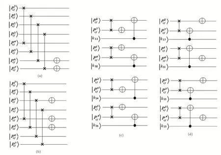
Fig.7 Quantum circuits of(a)Encoding algorithm A,(b)Encoding algorithm B,(c)Encoding algorithm C and(d)Encoding algorithm D.
4.2 Decoding Process
The decoding process of the proposed scheme can be done in the following steps:
Step 1Selecting the decoding algorithm based on the random binary key:
To decode the encoded image,according to the corresponding qubits of the key image,one of thealgorithms is employed to decode the pixels.This procedure is similar to the encoding procedure.
Table 2 shows the qubits of the key image and their corresponding decoding algorithm,and the quantum circuit of the selection procedure is shown in Fig.8.

Fig.8 Quantum circuit of corresponding qubits of the key image and selected decoding algorithm.

Table 2 Qubits of the key and corresponding encoding algorithm.
Step 2Applying the corresponding decoding algorithm on pixel:
In this step,according to the corresponding qubits of the key image,the decoder applies the corresponding decoding algorithms on the pixel.The four decoding algorithms are described as follows:
Algorithm A′This algorithm first applies NOT gates onqubits of the gray-scale value of a pixel.Then it swaps thequbits withandqubits respectively.
Algorithm B′This algorithm applies Not gates onqubits of the gray-scale value of the pixel.Then it swaps thequbits withqubits respectively.
Algorithm C′Using this algorithm,to decode the original value of qubitof the gray-scale value of a pixel;
(i)Ifcis an odd number,an NOT gate is applied on the qubit
(ii)Ifcis an even number,an XOR gate is applied on the qubitand the qubitof the key image and the resulted value is copied to
Then this algorithm swaps thequbits withqubits respectively.
Algorithm D′Using this algorithm,to decode the original value of qubitof the gray-scale value of a pixel;
(i)Ifcis an odd number,an XOR gate is applied on the qubitand the qubitof the the key image and the resulted value is copied to
(ii)Ifcis an even number,an NOT gate is applied on the qubit
Then this algorithm swaps thequbits of gray-scale value of the pixel withqubits respectively.Figure 9 shows the quantum circuits of these four decoding algorithms.
To more clarity,let us present a simple example.
Consider a simple 4×8 original image and a random binary key image as shown in Figs.10(a)and 10(b).By using the proposed algorithm,the original image can be simply encoded as shown in Fig.10(c),in which one can not obtain useful information.The detail of the encoding procedure is presented in Table 3.
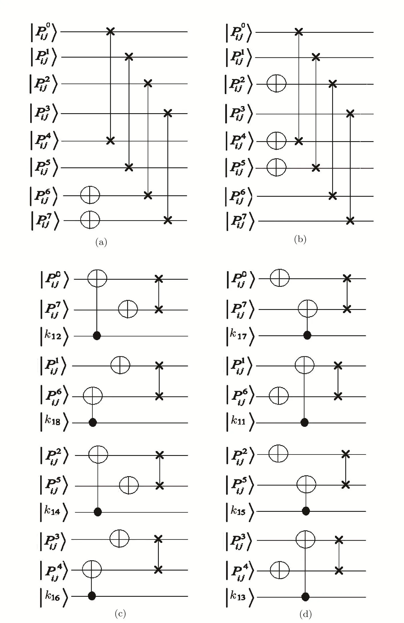
Fig.9 Quantum circuits of(a)Decoding algorithm A′,(b)Decoding algorithm B′,(c)Decoding algorithm C′and(d)Decoding algorithm D′.

Fig.10 (a)The original image.(b)The binary random key image.(c)Encoded image.

Table 3 Pixels of original image,corresponding qubits of the key,selected algorithm and output of the algorithm.
5 Simulations
Since the present state-of-the-art quantum hardware currently cannot go beyond proof-of principle examples,using a computer with Intel(R)Core(TM)i7-4500u CPU 2.40 GHz,8.00 GB RAM equipped with theMATLABR2015a environment,the proposed algorithm is evaluated by simulation.
In our simulation,we evaluate the results of applying our proposed encoding algorithm on some real images(Figs.11 and 12)by analyzing three essential properties,the histogram diagrams,the Peak Signal-to-Noise Ratio(PSNR),and the Shannon’s entropy.
Since the histogram diagram shows the affluence of pixels with every gray-scale value in image therefore,the histogram diagram of the encoded image has to be flatter than the original one’s,which can be quanti fi ed using Shannon’s entropy.
The original images,the encoded images and their corresponding histogram diagrams are represented in Figs.11 and 12.As seen in Figs.11 and 12,the histogram of the final encoded image is obviously flatter than the histograms of the original ones.
As seen in Figs.11 and 12,for an image with a smooth background such as the arrows case,which contains a few couple of gray-scale values where a discrete histogram diagram is achieved,the histogram of the encoded image is more flatter than the original image’s histogram,i.e.,the appearance of the gray-scale values of the final encoded image is changed seriously.The Shannon’s entropy is one of the useful properties to express the uncertainty of a series of random variables,which is used in information theory to quantify the minimum descriptive complexity of a random variable.For the case of an image,the amount of information that can be achieved from the image is indicated by entropy.
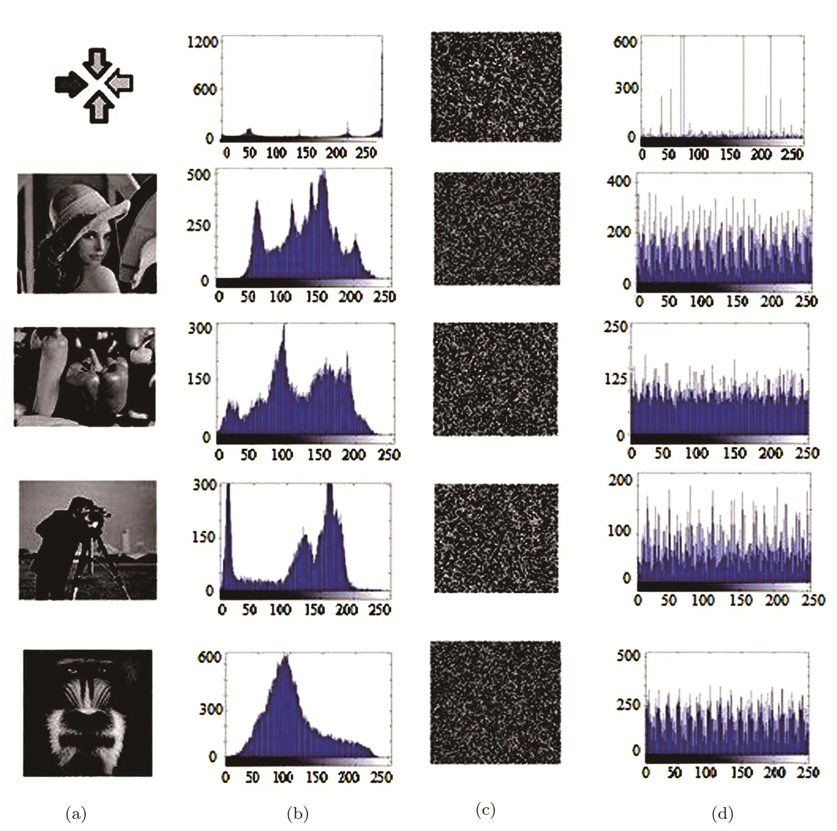
Fig.11 (a)Original image.(b)Histogram of the original image.(c)Encoded image,(d)Histogram of encoded image.
For a random variableX,withnoutcomes{x1,x2,...,xn},the Shannon entropyH(X)is defined as:

Obviously,if all pixels in an image have the same gray-scale value,the minimum entropy is achieved.On the other hand,when each pixel of an image presents a speci fi c gray-scale value,the image will exhibit maximum entropy,i.e.,the higher the value of entropy gets,the less information can be revealed.
The calculated Shannon entropy for the simulated sample images is presented in Table 4.As it is illustrated in Table 4,the encoding algorithm makes a considerable increase in the image’s entropies,therefore the proposed encoding method imposed a signi fi cant diversity or uncertainty to the original image.

Fig.12 (a)Original image.(b)Histogram of the original image.(c)Encoded image.(d)Histogram of encoded image.
Finally,The peak-signal-to-noise ratio(PSNR),can be considered as an efficient tool for comparing the fi delity of the encoded image with its original version.When evaluating an image encoding scheme,the original image can be assumed as a signal,and the encoded image can be assumed as a noisy signal.On the other hands,the more noisy signal(image)the better encoding procedure.The more noisy signal(image),the lower PSNR.
The PSNR is easily defined via the concept of the mean squared error(MSE).For twom×nmonochrome images(the original cover imageIand its stego versionK)the MSE is defined as

where,frepresents the matrix data of the original image,grepresents the matrix data of the decoded image,mrep-resents the numbers of rows of pixels of the images andirepresents the index of the row,nrepresents the number of columns of pixels of the image andjrepresents the index of the column,and the MAXfis the maximum of the signal value exists in the original image.
Needless to say,in using NEQR representation method,we are dealing with a standard 2D matrix of data.The dimensions of the original image matrix and the dimensions of the encoded image matrix are identical.The calculated PSNR for the simulated sample images is presented in Table 4.As it is illustrated in Table 4,using the proposed encoding method,for all of the considered original images,the calculated PSNR of the encoded images is less than 10,which means that the encoding algorithm strongly a ff ects the original image and makes it very difficult for an eavesdropper to obtain useful information from the encoded image.

Table 4 Calculated Shannon entropy for the simulated sample images.
6 Conclusion
A new secure efficient quantum images encoding algorithm is proposed.Here,four different encoding algorithms are introduced.In this method,for the aim of completing the encoding task,a randomized binary image key is generated during the procedure.Based on the both original images pixel and its corresponding qubits of the generated binary key,one of the four encoding algorithms is employed.
In the encoding step,the randomized key image not only is used to select the applying encoding algorithm for each pixel,but also some qubits of the key is used directly to change the gray-scale value of the pixel.This means that,if one does not have the randomized key images,it is impossible for him to decode the original image correctly.
From the experimental results,it can be seen that the proposed algorithm can effectively encode different kinds of images and the encoded images can not be decoded by an eavesdropper.The security and the applicability of the proposed algorithm are evaluated by computer simulation,where,analyzing the histogram diagrams,the Peak Signal-to-Noise Ratio(PSNR),and the Shannon’s entropy suggest the proposed method as an efficient scheme in quantum image encoding procedures.
[1]C.H.Bennett and G.Brassard,inProceedings of the IEEE International Conference on Computers,Systems and Signal Processing,Bangalore,India IEEE,New York(1984)p.175.
[2]Y.S.Zhang,C.F.Li,and G.C.Guo,Phys.Rev.A 64(2001)024302.
[3]N.Zhou,G.Zeng,W.Zeng,and F.Zhu,Opt.Commun.254(2005)380.
[4]M.Abdolmaleky,M.Naseri,J.Batle,et al.,Optik.128(2017)121.
[5]M.Naseri,Opt.Commun.282(2009)278.
[6]M.Naseri,Quantum Inf.Process.9(2009)693.
[7]N.R.Zhou,L.J.Wang,J.Ding,and L.H.Gong,Physica Scripta 81(2010)045009.
[8]M.Naseri,Int.J.Phys.Sci.6(2011)5051.
[9]X.B.Chen,Q.Y.Wen,F.Z.Gou,et al.,Int.J.Theor.Phys.6(2008)899.
[10]N.Fatahi and M.Naseri,Int.J.Theor.Phys.51(2012)2094.
[11]N.R.Zhou,L.J.Wang,J.Ding,et al.,Int.J.Theor.Phys.49(2010)2035.
[12]X.B.Chen,N.Zhang,S.Lin,et al.,Opt.Commun.281(2008)2331.
[13]S.Heidari and M.Naseri,Int.J.Theor.Phys.55(2016)4205.
[14]M.Naseri,M.Ahmadzadeh Raji,M.R.Hantehzadeh,et al.,Quantum Inf.Process.14(2015)4279.
[15]Xiu-Bo Chen,Zhao Dou,Gang Xu,et al.,Quantum Inf.Process.13(2014)85.
[16]Xiu-Bo Chen,Int.J.Quantum Inf.11(2013)13500101.
[17]N.Zhou,J.Li,Z.Yu,et al.,Quantum Inf.Process.16(2017)1.
[18]S.E.Venegas-Andraca and S.Bose,Storing,Processing and Retrieving an Image Using Quantum Mechanics,Proceeding of the SPIE Conference Quantum Information and Computation,Orlando,FL,United States,International Society for Optics Photonics,Vol.5105(2003)pp.137-147.
[19]J.I.Latorre,Image Compression and Entanglement.arXiv:preprint/quant-ph/0510031(2005).
[20]P.Q.Le,F.Dong,and K.Hirota,Quantum Inf.Process.10(2011)63.
[21]Y.Zhang,K.Lu,Y.H.Gao,and M.Wang,Inf.Process.12(2013)2833.
[22]P.Q.Le,A.M.Iliyasu,F.Dong,and K.Hirota,A Flexible Representation and Invertible Transformations for Images on Quantum Computers,In New Advances in Intelligent Signal Processing,Springer,Berlin,Heidelberg(2011)179-202.
[23]W.W.Zhang,F.Gao,B.Liu,et al.,Quantum Inf.Process.12(2013)793.
[24]X.H.Song,S.Wang,S.Liu,et al.,Multimedia Systems 20(2014)379.
[25]N.Jiang,N.Zhao,and L.Wang,Int.J.Theor.Phys.55(2016)107123.
[26]S.Miyake and K.Nakamae,Quantum Inf.Process.15(2016)1849.
[27]N.Jiang,L.Wang,and W.Y.Wu,Int.J.Theor.Phys.53(2014)2463.
[28]L.H.Gong,H.Song,C.He,et al.,Physica Scripta 89(2014)035101.
[29]N.Zhou,T.Hua,L.H.Gong,et al.,Quantum Inf.Process.14(2015)1193.
[30]M.Naseri,S.Heidari,R.Gheibi,et al.,Optik.131(2016)678.
[31]S.Heidari,M.Naseri,R.Gheibi,et al.,Commun.Theor.Phys.67(2017)732.
[32]R.G.Zhou,et al.,Quantum Inf.Process.14(2015)1717.
 Communications in Theoretical Physics2018年2期
- Communications in Theoretical Physics的其它文章
- Phase Transition and Physical Properties of InS?
- Parameterization of Nuclear Hulthén Potential for Nucleus-Nucleus Elastic Scattering
- Scalar Hidden-Charm Tetraquark States with QCD Sum Rules?
- Bilinear Forms and Soliton Solutions for the Reduced Maxwell-Bloch Equations with Variable Coefficients in Nonlinear Optics?
- Dirac Quasinormal Modes of Static f(R)de Sitter Black Holes?
- Thermodynamic Geometry of Charged AdS Black Hole Surrounded by Quintessence?
