Intelligent Energy Management Based on Predictive Control System of PHEV
2018-10-29 02:31:32ChenXinXueJianbo
汽車技術(shù) 2018年10期
Chen Xin,Xue Jianbo
(Schaeffler Trading(Shanghai)Co.,Ltd.,Shanghai 201804)
【Abstract】Rule-based energy management strategy used on Plug-in Hybrid Electric Vehicles(PHEV)has its innate disadvantage that the whole hybrid powertrain system has no choice but to reserve capacity as redundancy to response to the unpredictable driver behaviors in the near future,which could lead to non-optimal system efficiency as expected.This paper focuses on the optimization based algorithm for energy management and economic driving over a pre-selected horizon using messages from Intelligent Traffic System(ITS),which is proposed to schedule the charging or discharging of the high voltage battery,and when to turn on/off the engine and drive electrically.The benefits of the proposed predictive intelligent control strategy are shown by simulations with data extracted from mega city driving situation in Shanghai.
Key words:PHEV,Energy management strategy,Predictive intelligent control,ITS,Fuel economy
1 Introduction
The hybrid vehicle is one of the key solutions for increasing fuel economy and reducing greenhouse gas emission in automotive industry.Usually,the hybrid powertrain system is the hybrid of an Internal Combustion Engine(ICE),which has a smaller size but runs more efficiently,and an Electrical Motor(EM),which has the capability to shift the ICE load condition and recuperate the braking energy,and battery system.The opportunity for using different prime movers to satisfy the power demand allows the supervisory control to choose the energy flow between ICE and battery that maximizes global energy efficiency.In general,the fuel economy of a hybrid vehicle is much better than a vehicle with a conventional powertrain.
The modern Intelligent Traffic System(ITS)is based on advanced telematics,wireless connectivity and Global Position System(GPS).The value such information and preview can significantly enhance the energy efficiency of vehicles.For example,this information complements exists in vehicle navigation systems and help drivers in making better route choices to save traveling time and avoid traffic jams.The connection of these information systems and vehicle control system provides the opportunity to incorporate more environmental information than ever before into hybrid vehicle energy management.
In the energy management problem of hybrid vehicles,battery State Of Charge(SOC)is an important state parameter in determining the optimal power split ratio between ICE and battery.The SOC drops during the Charge Depleting(CD)operating distance as the vehicle drives electrically without assistance from the ICE.Once reaching the Charge Sustaining(CS)of SOC level,the SOC remains roughly steady while the ICE and the EM work together during CS operation.This strategy emphasizes that during CD operation,the EM satisfies the full vehicle power demand,and the ICE remains off.When the entire mission is known,optimization algorithms such as dynamic CD/CS programming can be used to find the optimal power split ratio.
The estimation of future driving conditions on a sliding window will become possible with improvements of ITS,which give more information about the velocity profile that enabled from traffic data,to vehicle control system.It provides an opportunity to develop an optimal energy management strategy,the control strategy estimates future power demand with a vehicle model and then uses dynamic programming on this estimation.In this paper,a predictive control strategy based on SOC pre-planning task under time-varying traffic conditions that have great value in motion planning of vehicles for fuel saving is considered.
2 Vehicle Model
2.1 Dedicated Hybrid Transmission
The hybrid vehicle studied uses a Dedicated Hybrid Transmission(DHT)as shown in Figure 1.Basically,with the realization of a DHT,the mechanical effort can be reduced potentially through an intelligent use of EMs.In this paper,a DHT concept merges the input power of an ICE and two EMs–input shaft electric motor(EM1)and output shaft electric motor(EM2).Each of these power units are connected to the drivetrain with 4 gear ratios.One dry multiple disc clutch connects and disconnects the ICE to/from EM1.Modes shown in Table 1 can be driven with the dedicated hybrid transmission.
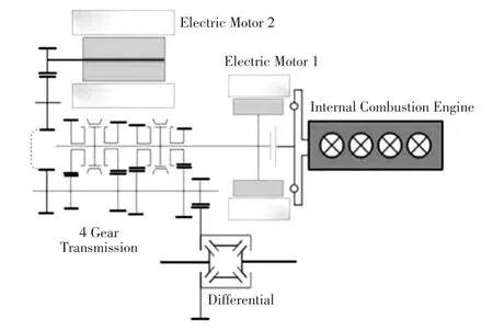
Figure 1. DHT concept
The dual-motors DHT structure enhances power passing through the high efficiency mechanical path,thereby improving the global efficiency of the powertrain.
2.2 Vehicle Parameters
In this paper,the model for Plug-in Hybrid Electric Vehicle(PHEV)with front wheel drive is used.The structure of the vehicle is shown in Figure 2.The hybrid powertrain system is integrated with a 1.5T gasoline engine,2 EMs,a 12 kW·h lithium-ion battery and a 4-speed transmission.
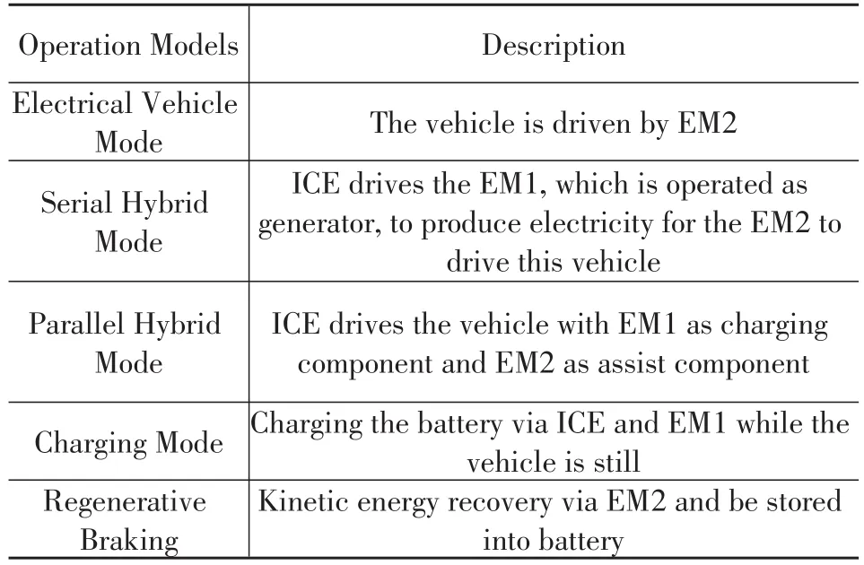
Table 1.Vehicle operation models
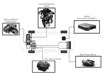
Figure 2.PHEV concept with DHT
Basic vehicle parameters are shown in Table 2.
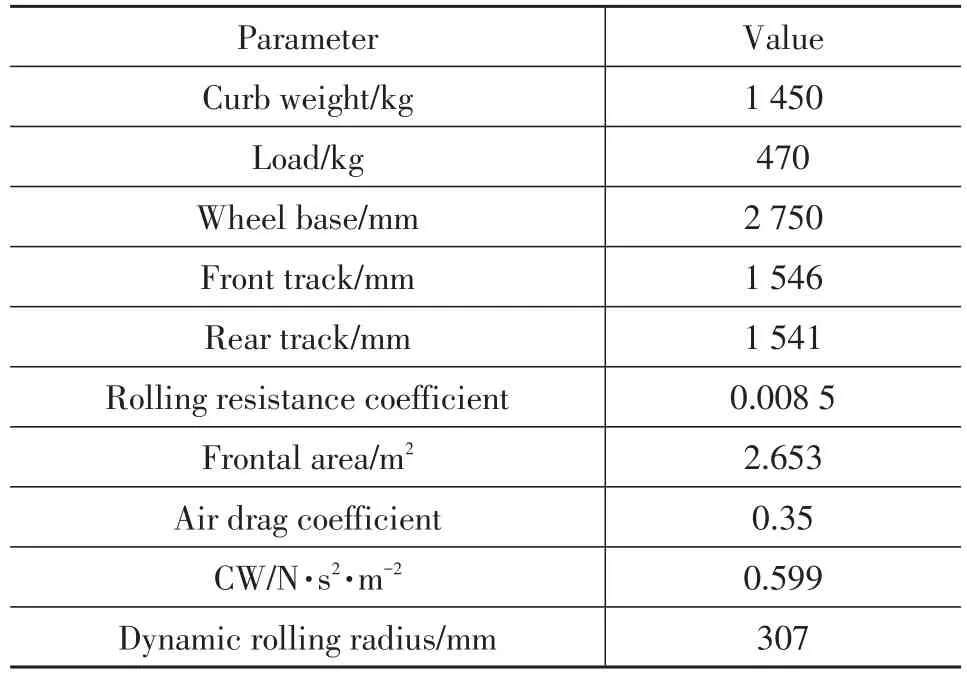
Table 2.Vehicle parameters
2.3 Longitudinal Dynamics
Here only the quasi-static torque states are analyzed for vehicle dynamics modeling requirement,which means the engine start/stop phases focusing on clutch torque control will be ignored.The disconnect clutch is considered to be naturally completely closed.The relationship between main components torque are shown in Figure 3.
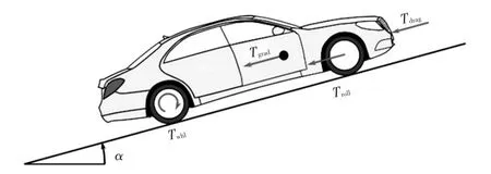
Figure 3.External torques on vehicle
The wheel torque can be expressed as:
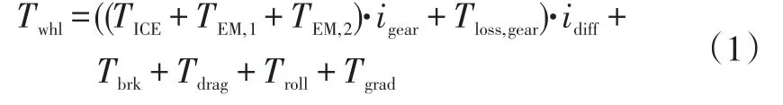
WhereTICEis the torque of internal combustion engine,TEM,1andTEM,2are the torques of input and output shaft electric motor separately,igearis the gear ratio,Tloss,gearis the transmission torque loss,idiffis the final ratio,Tbrkis the brake torque on wheels,Tdragis the air drag torque,Trollis the rolling resistance torque,Tgradis the road gradient torque.
Specifically the torque loss of transmission is given by torque loss mapTloss,gear(ωEM,1,TICE+TEM,1,χgear),whereχgearis the current gear andωEM,1is the rotational speed of electric motor on input shaft.
And all the resistant torques on wheels are introduced respectively:

WhereRwhlis the wheel radius,CAiris the air resistance coefficient,υ is the velocity of vehicle,μRis the rolling coefficient,αis the grade angle,mis the vehicle mass andgis the gravitational acceleration.
The vehicle longitudinal acceleration/deceleration behavior is described via the differential equation:
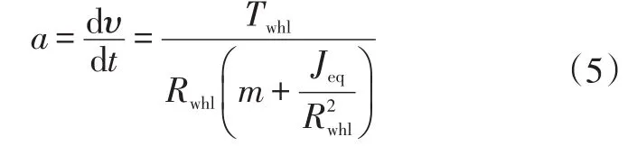
WhereJeqis the equivalent inertia,which includes all the inertias of the rotational components on the powertrain.
2.4 High Voltage Battery
In this paper,the model of high voltage battery is implemented according to the equivalent circuit theory,from which the characteristic is shown in Figure 4.The dynamics of batterySOCis calculated by
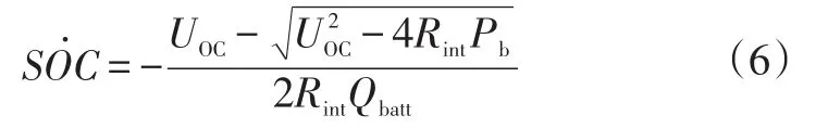
WhereUOCis the open circuit voltage of high voltage battery,Qbattis the battery capacity,Rintis the internal resistance dependent on temperature,current,Pbis the consumed/absorbed power of high voltage.
And the allowed use range of battery isSOC∈[25%,90%].
2.5 Navigation Interface
The navigation system shall provide information in Table 3 to fulfill the requirement of control strategy calculation.
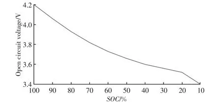
Figure 4.Relationship between open circuit voltage and SOC
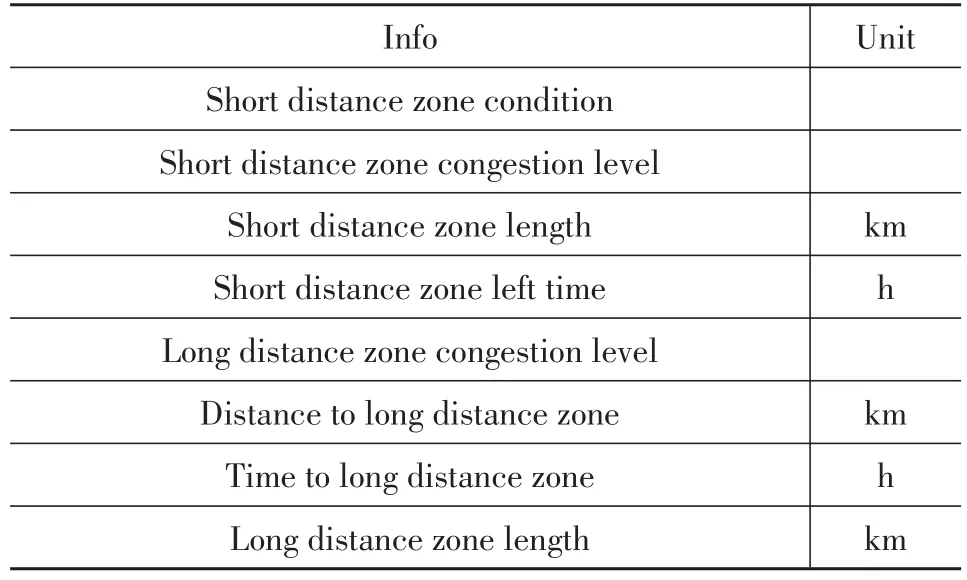
Table 3.Navigation information
According to the information from navigation,the entire road is separated into two sections:short distance zone and long distance zone as shown in Figure 5.Basically,they are distinguished by the congestion level,which is derived from average fleet velocity on the road.After the congestion level is defined,navigation system shall provide respectively the zone length and concurrent drive time in order to arrive the end of the zone and beginning of next zone.
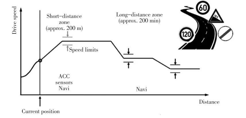
Figure 5.Navigation short/long distance definition
3 Predictive Energy Management
3.1 Optimization Criteria
The energy management control strategy shall control the three manipulated variables{TEM,1,TEM,2,TICE}set in order to minimize fuel consumption as well as CO2emission throughout the complete driving cycle.This problem is equivalent to a dynamic constrained optimization problem.
The determination of the cost function shall reflect the relationship between fuel consumption and electricity consumption.Normally the control strategy shall use electricity from high voltage battery as much as possible.However,sometimes vehicle cannot be charged via external charger within the current driving cycle,which means the electricity comes only from ICE.Given this situation,the cost function shall be defined as a sum of power of two power sources:
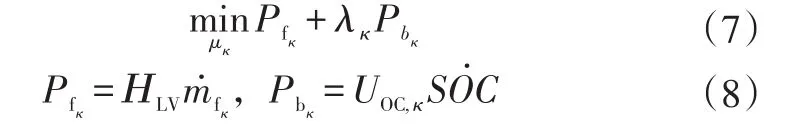
Whereκis the current step,HLVis the lower heating value of the fuel,in this case gasoline,m˙fκis the instant fuel consumption which could be calculated according to interpolation based on calibrated MAPm˙f(TICE,ωICE) as illustrated in Figure 6,ωICEis the rotational speed of internal combustion,λκis the so called equivalent factor,which indicates the equivalent consumed fuel power according to electricity consumed power during the real driving cycle.
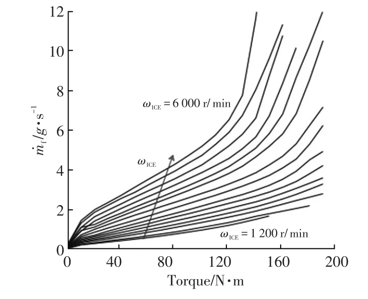
Figure 6. Fuel consumption rate with respect to torque curve for different engine speeds
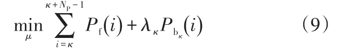
Thus the optimization criteria is derived from formula(7)and formula(8),but with some modifications to adapt the predicted horizon,in whichNPrefers to the predicted sampling steps in the future:
3.2 Predictive Control
The control used in this paper is formulated as a repeated solution of a finite horizon optimal control problem with respect to system dynamics,inputs and constraints.The optimal control objective or cost function is described as:
WhereωEM,2is the rotational speed of electric motor on output shaft,ηbis the efficiency of high voltage battery,ηEMis the efficiency of electric motors including control,Treqis the predicted torque demand for long horizon.
The instant fuel consumption rate is normally obtained from the engine test bench data,interpolated based on engine rotational speed and engine torque.
HereTreq(i)is based on collected information including reference velocityVrefas well as road grade from GPS,a driver model in combination with a simplified longitudinal vehicle model,all of which are used to calculate the combined power demandPreqfrom ICE and EM.The driver model consists of a PI controller.Furthermore,a holistic simple gear shift strategy is employed to determine the gear sequence.With the help of all above info,the predicted request torque is calculated as:
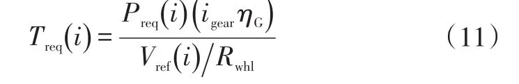
WhereηGis the efficiency of gear transmission.
Meanwhile,the rotational speeds of both power sources are concluded from

As a key factor during minimum consumed power iteration,equivalent factorλκshall be carefully calculated with the consideration of real time correction taken into account.Thus,the proposed solution can use an averagebased calculation over this penalty-adaption horizon,in combination with a proportional plus I-part feedbackSOCcontrol.The equivalent factor can vary between 0(battery full,electrical driving is for free)and around 5(battery is empty,electrical energy is very expensive):
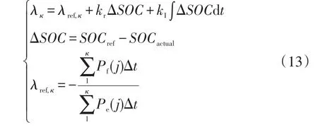
Whereλref,κis the basic equivalent factor which is depicted as the ratio between the energy consumption from both power sources till the current step,kris the proportional factor of equivalent factor feedback control,kIis the integration factor of equivalent factor,ΔSOCis the difference value between desiredSOC(SOCref)and actualSOC(SOCactual),
The expression contains also the feedback part(PI-part).The purpose of the latter part is to regulate the equivalent factor with regard to theSOCreference point(SOCref).
kris realized via a calibration curve based on ΔSOC.A curve was taken here because it gives the most flexibility,a linear or nonlinear dependence on theSOCdifference can be realized.The goal of the P-part is to make electrical energy expensive or cheap immediately when deviating too far fromSOCref.
The goal of the I-part is to avoid a permanent control deviation if the basic factor concluded from past does not fit to the future load pro file.If theSOCtrajectory is below the reference point,λincreases,therefore penalizing more the use of the battery.If theSOCtrajectory is greater than the reference point,λwill diminish and this will be translated into a greater use of the battery.
3.3 Implementation
Within each sampling period Δt,the energy management strategy implements the following steps:
a. Receive the future trajectory from GPS
b. Minimize the optimization criteria over the predicted horizon based on current state as well as past collected data using iterative search method
c.Apply for the control signal on the process during the sampling period of the calculator
Basically,the iterative method works in this way:The cost function is evaluated for each iteration step and the result is compared to the value from the last calculation.In case the new value is smaller than the last value,the new value is stored as new temporary minimum.All the potential engine operating points within this iteration are shown in an engine Brake Specific Fuel Consumption(BSFC)map in Figure 7.

Figure 7.Iteration search for ICE/EM operating points with respect to driver torque request as well as component boundaries
The solution boundaries for the control strategy calculation is determined based on the driver request torque,combustion engine operation range and limits of the electric motor(which consider the impact of high voltage battery state and limits of electric motor).
The maximum torque for the electric motor is limited to driver request torque minus engine drag torque.This is required in case the driver request torque is less than engine drag torque(due to brake request).If the strategy requested a torque greater than this limit,it would not be possible to fulfill the driver request.In order to avoid torque jumps,torque limits of the electric motor and the combustion engine are frozen if the variations in the values are very small and thereby improve drivability.
The optimal torque is then determined by an iteration loop which calculates the cost function within the electric motor limits.
An implementation scenario of predictive energy management in the vehicle control architecture owing interactions with other sub-systems is illustrated in Figure 8.

Figure 8. Integration of predictive energy management strategy in the vehicle control architecture
4 Results
4.1 Simulation Setup
The complete strategy verification and validation is held in Model-in-Loop(MiL)environment which is built with Simulink?basic models as well as its collateral toolbox Simscape?including Simscpae Driveline?and Simscape Power Electronics?.The simulation loop is shown in Figure 9.
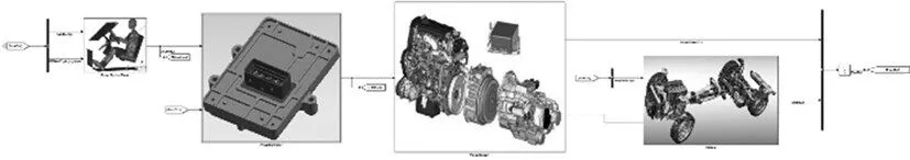
Figure 9.Simulation environment setup
4.2 Driving Cycle
The driving cycle considered to study the fuel efficiency is extracted from city road cycle close to city of Shanghai,from urban district of Pudong to another urban district of Jiading via middle ring fast way as well as some surface roads.It is designed to include all kinds of driving situations,i.e.intra-city freeway as well as road segment with typical congested situation.The driving cycle is shown in Figure 10.
As previously mentioned,the information from GPS basically consists of following items:
a. The length of short distance zone
b.The average fleet velocity of short distance zone derived from length and time
c.The length of long distance zone
d. The average fleet velocity of long distance zone derived from length and time
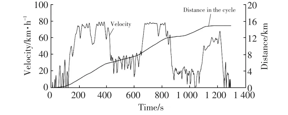
Figure 10.Driving cycle formulation
Based on the designed velocity profile,all above mentioned messages are concluded from it according to the requirement from navigation system,such as current road length and next congestion road length depicted in Figure 11.
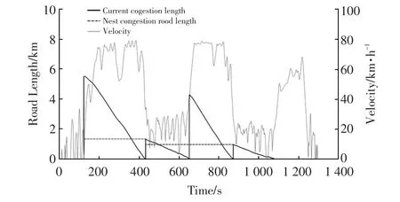
Figure 11. Driving cycle formulation
4.3 Control Strategy Performance
The engine start/stop performance is shown in Figure 12.The predictive energy management foresees the future congestion road,and therefore starts the engine more frequently in the freeway.There are mainly two reasons:first,the engine could be operated at points with much higher thermal efficiency in freeway in combination with appropriate gear choice;second,longer engine running time could create opportunities to charge the high voltage battery,which could save energy for future congestion roads.Under those circumstances,pure electric drive will be absolutely helpful for saving energy and improving general efficiency.
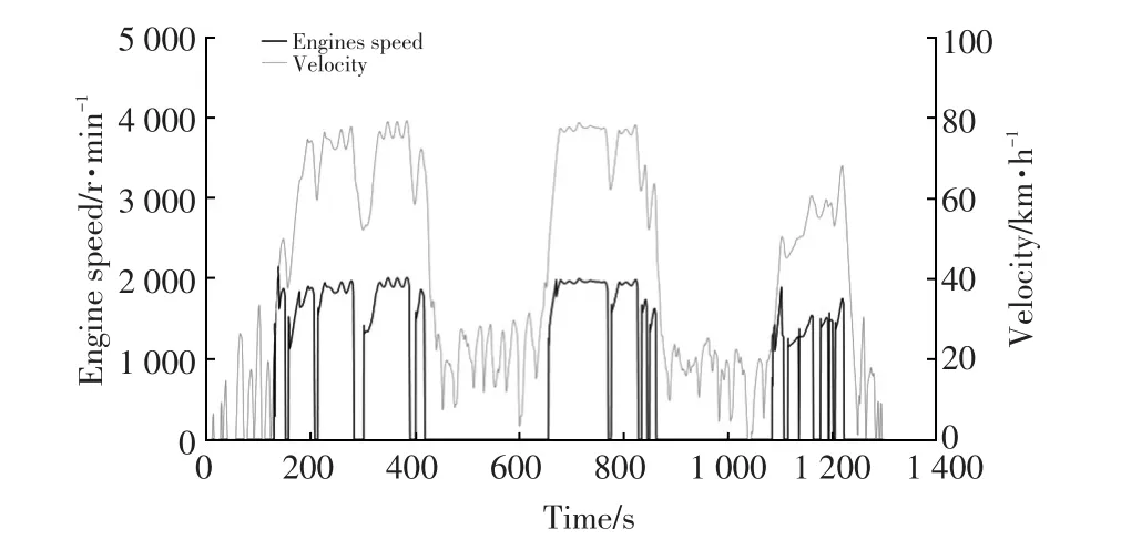
Figure 12. Engine start/stop performance with predicted energy management
The trajectory of high voltage batterySOCin Figure 13 reflects the same rationale.Also,the targetSOCtrajectory which results from predictive energy management fits the one in real world as shown in Figure14.
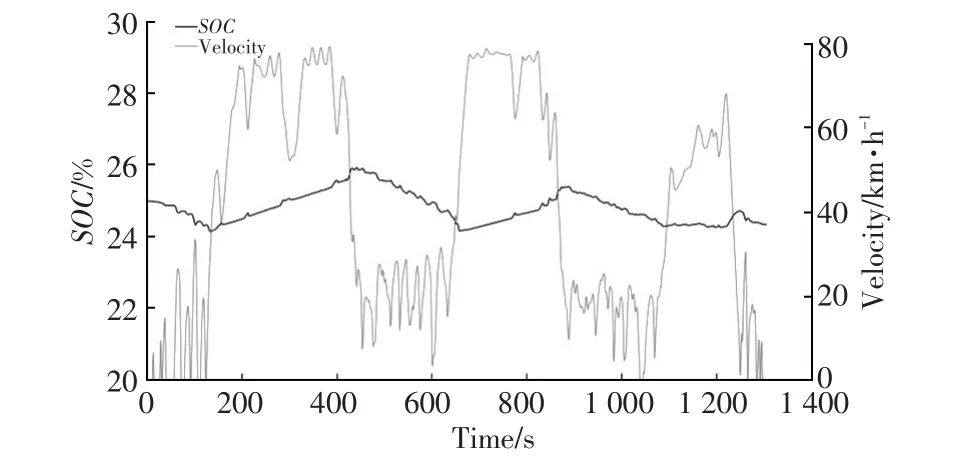
Figure 13. SOC performance with predicted energy management

Figure 14. Comparison of SOC performance and its target
4.4 Comparison with Non-Predictive Strategy
Compared with conventional rule based energy management strategy,a more frequent engine start/stop behavior is monitored in Figure 15.Especially under low velocity circumstance,the operating points of engine are distributed mostly under 1 500 r/min,which will certainly introduce deterioration of fuel economy.Furthermore,the frequent engine restarts make no benefit to emission.
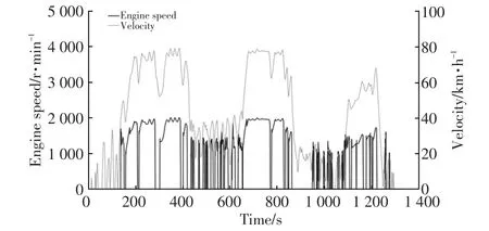
Figure 15.Engine start/stop performance with rule based energy management
Another side effect of non-predictive energy management is the one-way trajectory ofSOC.As shown in Figure 16,theSOCkeeps the trend of continues decrease all along the road.In real driving situation,SOCwill certainly fall below the minimum allowed value till the end of vehicle usage.It will decline the freedom of electricity usage and undermine the ability to regulate the engine operating points with the help of battery intervention properly.The results in Table 4 indicates the predictive energy management can save up to 5%in fuel consumption compared to rule based strategy for this driving cycle.It also manages to track theSOCtrajectory very well and the mean error is less than 1.0%.Meanwhile the instantaneous nature of the controller leads to improvements in the engine on/off events and differences in engine off time.
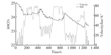
Figure 16.SOC performance with rule based energy management
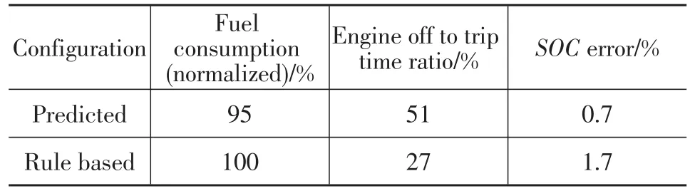
Table 4.Simulation results:comparison between different strategies
5 Conclusions
The main purpose of this paper is to propose a global optimization algorithm to control hybrid vehicles to meet real time requirement in optimality.The future driving conditions can be predicted via different kinds of future information including trip distance,traffic flow,etc.We used this information in a predictive control energy management of plug-in hybrid electrical vehicle and show noticeable benefit of predictive control for SOC control and fuel consumption.The predictive control applies a dynamic algorithm to reduce computation time in order to implement this strategy in a real-time system.
We proved that the optimal control based on the assumptions of the batterySOC,which are reasonable in a CS optimal control problem of PHEVs.Based on the assumption and for this hybrid configuration with the predictive energy management,theSOCcan be considered as a PI part;it simplifies the optimal control problem.Simulation clearly showed the benefits of a definite predictive horizon on fuel consumption for the studied PHEV.