Active disturbance rejection control:some recent experimental and industrial case studies
Qing ZHENG,Zhiqiang GAO
1.Department of Aerospace,Industrial,and Mechanical Engineering,California Baptist University,Riverside,CA 92504,U.S.A.;
2.Department of Electrical and Computer Engineering,Cleveland State University,Cleveland,OH 44115,U.S.A.Received 16 July 2018;revised 22 October 2018;accepted 22 October 2018
Abstract
This paper presents a summary of some recent experimental and industrial case studies of active disturbance rejection control(ADRC).ADRC is a novel disturbance estimation and rejection concept,leading to a new technology with a distinct advantage where,unlike most existing methods,disturbances,internal and external,are actively estimated and rejected.Applications of the new approach in solving industry-wide bench mark problems have led to a slew of innovative solutions.The scope of the applications shown in this paper includes motion control,robotic-enhanced limb rehabilitation trainings,fuel cell systems,and the two-mass-spring benchmark problem.Recent production line validation results obtained are also included.
Keywords:Active disturbance rejection control,applications,production line validation
1 Introduction
Active disturbance rejection control(ADRC)[1–5]as a design framework represents a rather drastic departure from classical as well as modern control theory.To understand it,let us briefly review the way a control problem is normally perceived and dealt with.Feedback control can be viewed as a means to modify the dynamics of a given process,also known as the plant,so that it behaves in a desirable manner.This requires that the controller overcomes 1)the internal dynamics of the plant,and 2)the external disturbances.For example,consider a process governed by Newtonian law of motion

whereyis the position output,uis the force input generated by the actuator,andf(,y,w)accounts for all other forces exceptu,andwis an external disturbance.Let

represent the desired dynamics(reference),the control problem becomes that of synthesizing a control law

such that the process in(1)behaves as(2).
This is where the commonality ends for the two schools of thoughts on controls:the mathematical approach and the experimental approach.The former requires that,in the case of(1),the mathematical expression off(,y,w)be obtained,upon which a set of analytical methods can be applied.For example,the well-known pole-placement and feedback linearization techniques essentially cancel the process dynamics and replace it with the desired one,i.e.,

The reason that this type of methods may not be the most practical one is perhaps two-fold:finding the mathematical expression off(,y,w)is 1)not trivial;2)not necessary.
In many decades of control practice,engineers have invented and experimented with different control mechanisms in(3),often with little knowledge of the plant dynamics.This is referred to as the experimental approach here.A prime example is the proportionalintegral-derivative(PID)controller[6,7],which is reportedly being used in over 90%industrial control applications today[8].The PID controller

wheree=r?yis the difference between the desired and the actual output,kp,ki,andkdare controller parameters,combined with the plant yields

The successof PID indicates that the term in parenthesis in(6)isable to overcomef(,y,w)in most applications.It seems that a good control law can be found largely independent on the process dynamics.Furthermore,if the information onf(,y,w)can be somehow extracted from the input and output data of the process,would it help to make the above control law more effective?The answer to this question led to ADRC.
ADRC is an unconventional design strategy.The key idea is to treatf(,y,w)in(1)as a state variable,which can be estimated by a state observer.Then the control law in(4)can be realized without the mathematical expression off(,y,w).The needs for a rigorous mathematical model has been attributed,in part,as an underlining issue that leads to the theory-practice gap in the many areas of controls[9–12].The development of ADRC perhaps offers a different perspective on this important subject.
ADRC was originally proposed by J.Han[1–3],further developed,simplified and articulated in[4].The potential of ADRC as an effective new control design tool is evident in many case studies,where the technique is used to tackle a number of benchmark problems in different industry sectors with promising results[13–24].This paper provides readers with a summary of these studies where they can assess the scope and novelty of such a design method and philosophy.
This paper is organized as follows:The ADRC design principle and the theoretical justification are described in Section2.Some recent experimental and industrial case studies are summarized in Section3 and Section4 respectively.Finally,concluding remarks are given in Section5.
2 Active disturbance rejection control
2.1 Design principle
ADRC offers a new and inherently robust controller building block that requires very little information of the plant.Based on the extended state observer(ESO),this control algorithm actively estimates and compensates for,in real time,the effects of the unknown dynamics and disturbances,forcing an otherwise unknown plant to behave like a nominal one.Such strategy leads to the ditching of the prevailing model requirement in the current design.That is,instead of depending on the model of the plant,the controller draws the information needed to control the plant from the ESO.For the sake of simplicity,the plant in(1)is used as the theme problem to illustrate the ADRC-based control design.
Letx1=y,x2=,andx3=f(,y,w),the augmented state space form of(1)is

where

Note thatx3=f(y,y,w)is the augmented state andh=f(,y,w)isusually unknown butbounded.The idea is that,based on(7),a state observer such as

with the observer gain

can be constructed so thatzaccurately estimatesx.This observer is denoted as the linear ESO.The observer gains are chosen such that the characteristic polynomials3+l1s2+l2s+l3is Hurwitz.For tuning simplicity,all the observer poles are placed at?ω0.It results in the characteristic polynomial of(8)to be λ0(s)=s3+l1s2+l2s+l3=(s+ ω0)3where ω0is the observer bandwidth andL=[3ω03]T.Generally,the larger the observer bandwidth is,the more accurate the estimation will be.However,a large observer bandwidth will increase noise sensitivity.Therefore a proper observer bandwidth should be selected in a compromise between the tracking performance and the noise tolerance.
With a well behaved observer,the observer statez3will closely trackx3=f(,y,w).The control law

will then reduce the plant(1)to an approximate unit gain double integrator,i.e.,

Let

The closed-loop system(11)will approximate the design goal in(2).An example of suchu0is the common proportional-derivative control

whereris the desired trajectory.Note that a feed forward mechanism is employed in(13)for the purpose of reducing the tracking error.In equation(13),kpandkdare the controller gain parameters selected to makes2+kds+kpHurwitz.For simplicity,letkp=,kd=2ωc,where ωcis the controller bandwidth.
In practice,the controller bandwidth,ωc,is tuned based on how fast and steady we want the output to track the setpoint.A large controller bandwidth generally increases the response speed but it may push the system to its limit,leading to oscillations or even instability.Thus the controller bandwidth should be adjusted based on the competing requirements of performance and stability margin,together with noise sensitivity.In addition,a large controller bandwidth usually increases the magnitude and rate of change in control signal,and therefore the operation cost.The observer is tuned in a similar way:adjusting its bandwidth,ω0,for a trade-off between tracking performance and noise sensitivity.
The primary reason for this particular parameterization and tuning method is practicality:the observer and feedback gains must be easily tunable by most engineers,who are usually familiar with the concept and implications of bandwidth.It is advantageous that engineers could use a completely new design method without losing the critical insight gained from classical control:frequency response.
Remarks1)The gains in both the observer in(9)and the PD controller(12)are,in general,nonlinear,as shown in[1–3].The linear version is used here for the sake of tuning[4]and simplicity of presentation.While the nonlinear gains may be more effective,they also produce extra complexity in the control algorithm implementation and tuning.In addition,stability of the system becomes more difficult to prove.
2)This design strategy does not require an accurate mathematical model of the plants.It is not limited to the systems of the form of(1).The extension to higher order systems is shown in[13,25,26].
3)The combined effects of the unknown disturbance and the internal dynamics are treated as a total disturbance.By augmenting the observer to include an extra state,it is actively estimated and canceled out,thereby achieving active disturbance rejection.
2.2 The theoretical justi fi cation of ADRC
The systems that ADRC aims to manage may be uncertain,nonlinear,and time-varying.In addition,the disturbance signal may not be continuous.These make the theoretical analysis extremely challenging.With the great success of ADRC practical applications,researchers have gradually made progress on the theoretical justification of ADRC.The initial convergence analyses of linear ESO estimation error dynamics and linear ADRC closed-loop tracking error dynamics for both single-input and single-output(SISO)and multipleinput and multiple-output(MIMO)systems are shown in[13,25–27].The frequency analyses of linear ADRC are given in[28–30].The stability characteristics for nonlinear ESO and nonlinear ADRC are analyzed in[31–33].The transient performance and the stability of linear ADRC for nonlinear uncertain systems are discussed in[34–36].The idea of linear ADRC has been used to stabilize one-dimensional and infinite-dimensional systems with boundary input disturbance[37,38].The stability of nonlinear ADRC for SISO systems via the circle criterion method is analyzed in[39].The conditions of exponential stability in ADRC based on singular perturbation analysis are presented in[40].An ESO for output tracking of MIMO systems with mismatched uncertainty and the stability analysis are given in[41].Most recently,several modified ADRCs for nonlinear uncertain systems with time delay are studied and compared with theoretical analysis[42].The theoretical research on stability analyses provides solid foundation for practitioners to understand and design ADRC systems based on the need.
3 Practical applications of ADRC
The effectiveness of ADRC is tested on several common industrial control problems in this section,including motion control,robotic-enhanced limb rehabilitation trainings,fuel cell systems,and the two-mass-spring benchmark problem.
3.1 Motion control
Motion control applications can be found in almost every sector of industry,from factory automation and robotics to high-tech computer hard-disk drives.They are used to regulate mechanical motions in terms of position,velocity,acceleration,and/or to coordinate the motions of multiple axes or machine parts.In a typical application using a motor as the power source,the equation of motion can be described as(1).Obviously,ADRC is a natural fit for this class of problems.By estimating the combined effects of internal dynamics and external disturbances,represented byf(,y,w),the controller proves to be highly tolerant of dynamic variations and disturbances commonly found in manufacturing processes.In[17],the resonance problems in motion control,typically described in a two-inertia system model as compliance between the motor and the load,are studied.
The problem is formulated in the linear ADRC framework and the resonance is taken as disturbance to be estimated and mitigated.The proposed control solution to the vibration problem is verified in both simulation and hardware tests for the velocity control with motor feedback case.The experiments are conducted on the torsional apparatus Model205 from Educational Control Products(Bell Canyon,CA,USA).The results are shown in Fig.1.Both motor response and load response track the reference very well before the load change.The robustness of the control method is tested.The motor velocity remains well controlled with the load change.But the load exhibits oscillations as expected,since resonant frequency is lowered with the load increase and the previous profile is a little fast compared to the new resonance.Test results show that decreasing the rising time to one second will greatly reduce the oscillations.The frequency responses for both open-loop and closedloop systems are analyzed.The resonant mode of the system is attenuated by applying ADRC[17].

Fig.1 Velocity control test results[17].
3.2 Robotic-enhanced limb rehabilitation trainings
Rehabilitation robotics is becoming more and more important in physiotherapists’routine work.To improve the treatment performance,such as reducing the recovery period and/or monitoring and reacting to unpredictable situations,the rehabilitation manipulators need to help the patients in various physical trainings.The most widely performed rehabilitation trainings are those based on isometric and isotonic exercises[18].A special case of the ADRC is applied to govern a proper realization of basic limb rehabilitation trainings in[18].The experimental study is performed on a model of a flexible joint manipulator,whose behavior resembles a real robotic rehabilitation device.
The experimental setup in this study is the changeable stiffness manipulator(CSM),a one degree-of-freedom,rigid-link,flexible-joint manipulator.The experimental results for the isometric exercises and the isotonic exercises are shown in Fig.2 and Fig.3,respectively.The obtained practical results demonstrate the ADRC based on perturbation simultaneous estimation and compensation provides an effective and robust solution for the robotic-enhanced limb rehabilitation trainings.
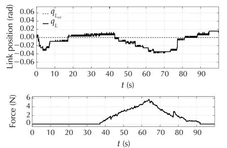
Fig.2 Isometric training:actual and reference link angular position in relation with the force generated by the link[18].

Fig.3 Isotonic training:reference and actual force exerted on the link in relation with the angular position of the link[18].
3.3 Fuel cell systems
Fuel cell is a power supply system,which takes advantage of the electro-chemical reaction between oxygen and hydrogen to produce electricity with water as its byproduct.As the byproduct is only the water,using fuel cell systems can effectively reduce emissions of carbon dioxide.Therefore,fuel cell systems are under extensive development for many power applications.A centrifugal compression system is used to supply the compressed air to the fuel cell,thereby reacting with the hydrogen to produce electricity.Because of this compressor’s ultra-high speed,it has a great advantage of ultra-compactness,which makes it more suitable for transportation applications.However,unlike positive displacement compressors,the centrifugal compressor has strong coupling between mass flow and pressure,which gives rise to the difficulty of control and also limits its operating region.In[20],a unique dynamic disturbance decoupling control(DDC)strategy based on ADRC is developed to control the mass flow and pressure simultaneously.
To demonstrate the effectiveness of the decoupling,step changes are commanded to the mass flow reference and pressure reference respectively,and corresponding responses are observed and compared with a conventional PI controller.Figs.4 and 5 show the dynamics of the system outputs during a step change(from 12g/s to 14g/s)of the mass flow command.

Fig.4 Responses of the output variable under amass flow step command[20].
From the experimental results,it can be observed that:during the transient,the ADRC based DDC exhibits a faster response than the PI control;in the meanwhile,the pressure controlled by DDC has much smaller deviations caused by the mass flow change.In the steady state,both the mass flow and pressure have smaller ripples with DDC.The experimental results demonstrate the DDC performs better in both the transient and steady states compared with a traditional PI controller.This control system has been validated on a 10kW fuel cell model under load variations[20].
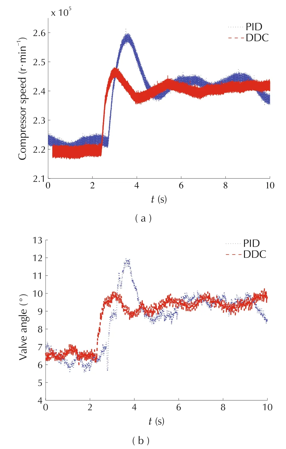
Fig.5 Actuator dynamics under a mass flow step command[20].
3.4 Two-mass-spring benchmark problem
Vibration suppression or isolation is important in a variety of industry sectors because mechanical resonance physically exists in nearly all mechanical systems,such as the automobile suspension systems.Some resonant modes can be ignored all together if their natural frequencies are far beyond the bandwidth of the closed loop control system;others must be dealt with deliberately to avoid vibration and instability.A two-massspring system,which can be seen as an equivalent system for most typical vibration systems,was formulated by Wei and Bernstein in 1990 as a benchmark problem[43].What makes the benchmark problem challenging is the uncertainties in the system dynamics and in the external forces.Typical in the current solutions is the practice of treating separately the robustness problem caused by the uncertainties in the internal dynamics,and the rejection of the external disturbance.The control problem is artificially split accordingly into two separate problems,i.e.,the regulation problem and the robustness problem.
In[23],a unified ADRC framework is proposed to deal with the vibration and robustness issues all at once,in the absence of a detailed plant model.A general schematic of the two-mass-spring system is given in Fig.6,which consists of two massesm1andm2that are free to slide over a frictionless horizontal surface.The states of the system are conveniently defined as the displacements and velocities of the two masses,respectively,wherex1andx3denote the displacement and velocity of massm1;andx2andx4as that of the massm2.

Fig.6 Two-mass-spring system with uncertain parameters[23].
In this study,the information of the known part of the total disturbance is employed in the ESO design,which is donated as the Gray Box Approach.An initial kick is applied to the right mass carrier as the impulse disturbance.The response of the drive mass and load mass are shown in Fig.7.Both drive mass and load mass is driven back to their initial position in a short period of time with little oscillation.The robustness of the proposed control solution is then verified by adding one brass mass block to both of the mass carriers and the response hardly changes as shown in Fig.8.Test results
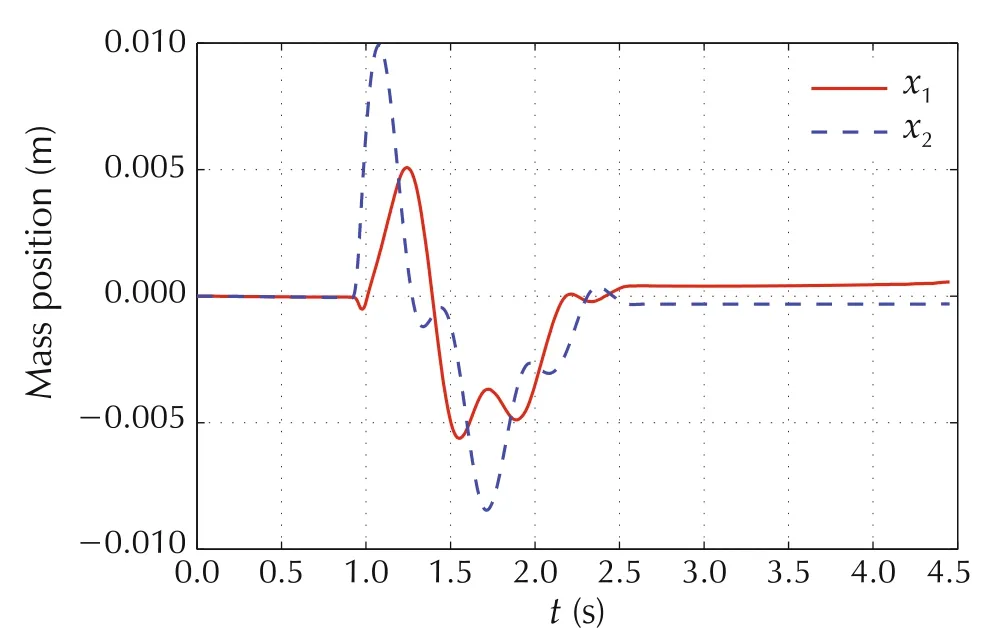
Fig.7 Hardware experiment result of the gray box approach[23].
4 Validation of assemly line applications
Recently,the ADRC design strategy has been put under rigorous test by the third party on production lines equipment.Some results shown in this section demonstrate the effectiveness of ADRC with great economic implications.
show that the proposed solution is very insensitive to model uncertainties.

Fig.8 Hardware experiment result of the gray box approach with model uncertainties[23].
4.1 Industrial servo drive
A leading provider of servo drives tested ADRC on a variety of motor drive configurations.Their controls expert pitted ADRC against their PID alternative.It took him 45 minutes to tune their system;he spent 2minutes configuring ADRC.Figs.9–11 show big improvements in error and jerk reduction and energy savings.
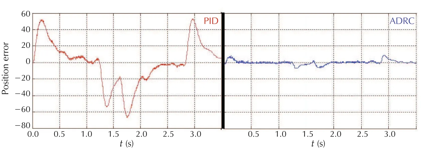
Fig.9 81%reduction in maximum position error.
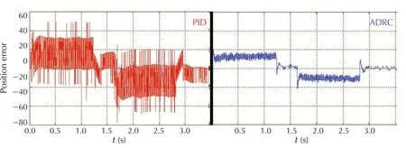
Fig.10 41%reduction in RMS torque.
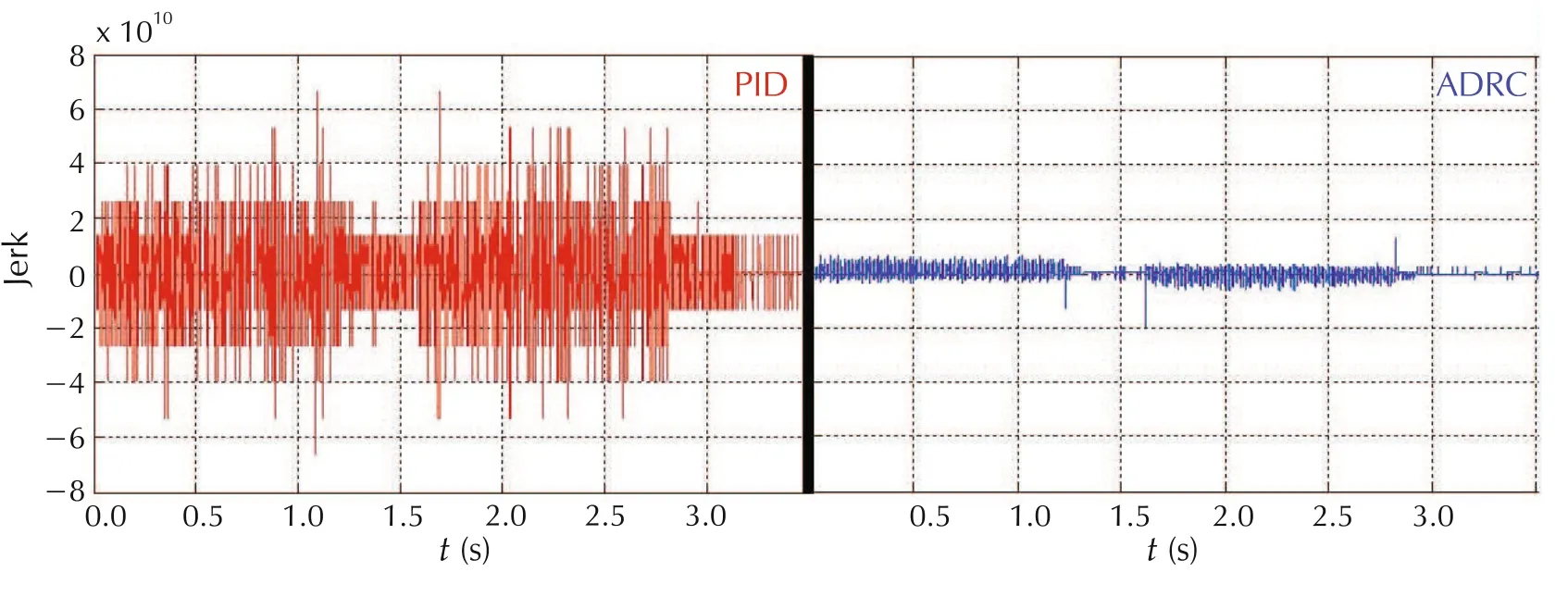
Fig.11 71%reduction in jerk.
4.2 Temperature control in hose extrusion
ADRC was implemented for multivariable systems as a DDC approach by Line Stream Technologies Inc.across production lines at a Parker Hannifin hose extrusion facility in North America[15].Because of the production down time must be kept minimum,the implementation of the proposed method was carried out with minimum knowledge of plant dynamics.There was no modeling or simulation test done before the final deployment of the new algorithm,a typical scenario in an industrial setting.But results,once the switch is flipped and the new algorithm takes charge,were both sweeping and immediate:across ten production lines,the energy consumption drops by an average of over 50%and the process performance index(Cpk)is improved by over 30%.“The implementation was simple”,according to Scott Burrow bridge,Parker’s control engineer, “I sent them our existing PLC program over email,and a week later they showed up and installed the new program during shift changeover.”The results were unmistakable – heat zones chieved equilibrium with little to no temperature fluctuation,and the power meter readouts“l(fā)ook like they fell off a cliff”[44].
The extrusion lines are quite typical industrial processes where there are strong interactions among the process variables.That is,the fluctuations of one process variable tend to propagate along the production line as the existing PID controllers,designed without any considerations for such interactions,almost always have a difficult time dealing with them.The end result is usually observed in the form of continuously overshooting and undershooting in the target temperatures,also known as cycling in practice.
DDC,on the other hand,actively estimate and reject such interactions,BEFORE they result in temperature fluctuation,as evident in the Parker plant:we run the production lines for 24 hours with the PID controllers in each loop,and then switched control algorithm from PID to a DDC.We observed that after 15 minutes,temperature fluctuations stopped,overshoot disappeared,cooling fans were turned off automatically,and the energy consumption was reduced by over 50%,as shown in Figs.12–19,with the energy savings of production lines 1–8.
From Figs.12–19,it can be observed that the DDC approach results in over 50%energy reduction in all the production lines.Note that testing DDC is quite simple.To eliminate potential switching risks,Line Stream engineers installed the DDC software in parallel with the existing logic.This allows manufacturers to switch between DDC and the existing control program for comparative performance testing.This also gives manufacturers the peace of mind they can always return to exactly how things were originally[44].

Fig.12 Energy savings in a hose extruder production line 1.
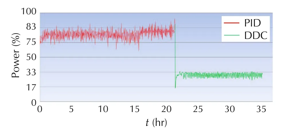
Fig.13 Energy savings in a hose extruder production line 2.

Fig.14 Energy savings in a hose extruder production line 3.
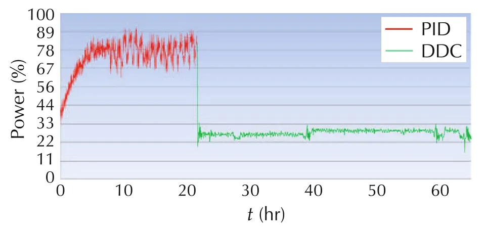
Fig.15 Energy savings in a hose extruder production line 4.
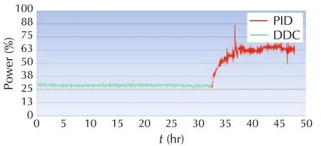
Fig.16 Energy savings in a hose extruder production line 5.
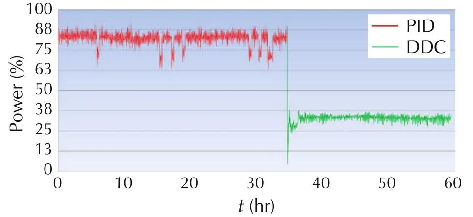
Fig.17 Energy savings in a hose extruder production line 6.
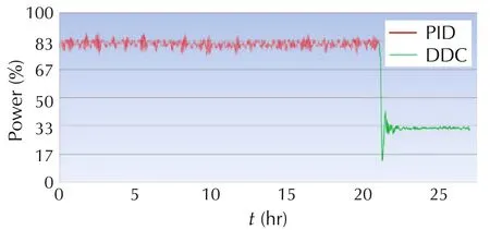
Fig.18 Energy savings in a hose extruder production line 7.

Fig.19 Energy savings in a hose extruder production line 8.
4.3 The new chipset from TI
In 2013,Texas Instruments announced the new Insta SPIN(TM)-MOTION motor control technology,which is based on ADRC.It achieved improved motion and efficiency for advanced motor control designs in minutes[45].The new Insta SPIN(TM)-MOTION technology has been adopted in the TMS 320F2806x M series.“Spin TAC constitutes a comprehensive motion control software suite that delivers optimized performance across speeds and loads.Key benefits include:1)simplified tuning,2)intuitive trajectory planning,3)mechanically sound movement,and 4)ideal control:benefit from the most accurate speed and position control on the market,based on Line Stream’s patented Active Disturbance Rejection Control,”stated by Texas Instruments[46].Fig.20 shows the disturbance rejection test comparison between PID and Spin TAC controllers.

Fig.20 The disturbance rejection test comparison between PID and Spin TAC controllers[46]by Texas Instruments.
Fig.21shows the speed tracking error comparison bet ween PID and Spin TAC controllers.They clearly demonstrate the greatly improved performance with SpinTAC.
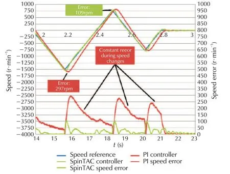
Fig.21 The speed tracking error comparison between PID and SpinTAC controllers[46]by Texas Instruments.
4.4 Power regeneration
In this application,ADRC is tested in a regenerator of a 1000 MW in-service power plant,as shown in Fig.22.

Fig.22 Illustration of the regenerator[47].
The regenerator is a surface-type heat exchanger that is used to heat the working fluid by the high-temperature steam extracted from the turbine.The controlled variable is the level of the condensate.The manipulated variable is the#1 valve position that controls the condensate flux to the next regenerator.The three major disturbances are:the steam flux from the turbine,the working fluid flux,and the opening position of the#2 valve.Unlike the frequent disturbances from steam and working fluid,the#2 valve is usually closed if no emergency occurs[47].
The ADRC control logics with well-tuned parameters were downloaded into the digital processing unit(DPU)of the distributed control system(DCS)and a field test is carried out.After bumpless transfer to ADRC,the test is implemented by changing the setpoint from 70 mm to 30 mm and then changed to 500 mm.The tracking performance of the ADRC controller is shown in Fig.23.It can be seen that the controlled variable tracks the desired tracking trajectory very well despite the modeling inaccuracyand frequent disturbances from the shell and tube sides.To test the regulatory performance,a à10%disturbance of the opening position is arbitrarily added to the#2 valve.The comparison results of the ADRC and PI controller are shown in Figs.24 and 25.
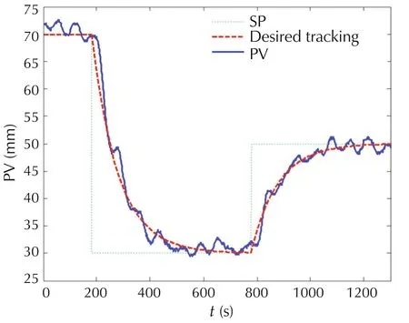
Fig.23 Tracking performance of the ADRC controller[47].

Fig.24 Field test result of the ADRC controller(The time span is 33 min)[47].
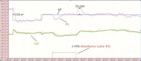
Fig.25 Field test result of the PI controller(The time span is 60 min)[47].
Note that the PI controller parameters are tuned by the experienced engineers,based on trialand error,with the goals to fulfill both requirements on disturbance rejection and setpoint tracking.From Figs.24 and 25,it can be observed that compared with ADRC,the PI controller produces a much more sluggish regulatory response although the resulting tracking performance has already been tuned to be faster than expected.Moreover,the ADRC solution does not have proportional kick in setpoint tracking while the PI controller does.The field tests verify the effectiveness of ADRC in power regeneration application[47].Both the setpoint tracking performance and the disturbance rejection performance are well achieved.
5 Conclusions
The ADRC design strategy and its applications are discussed.It is shown that this method provides an alternative design framework in solving industrial control problems,without the need for an accurate mathematical model.Instead,the combined effect of the internal dynamics and the external disturbances is estimated and actively rejected.It is observed that the same design concept has been successfully applied to SISO and MIMO problems of vast different characteristics,including linear,nonlinear,internal dynamic variations,and external disturbances.It is shown that the ADRC has strong disturbance rejection ability and is highly robust.The production line data further demonstrates ADRC as a trans formative control technology and its potentials.
 Control Theory and Technology2018年4期
- Control Theory and Technology的其它文章
- From flatness,GPI observers,GPI control and flat filters to observer-based ADRC
- Embedded model control:Reconciling modern control theory and error-based control design
- Development of nonlinear disturbance observer based control and nonlinear PID:A personal note
- Intelligence evolution for service robot:An ADRC perspective
- Active disturbance rejection based load frequency control and voltage regulation in power systems
- Editorial
