Application of novel force control strategies to enhance robotic abrasive belt grinding quality of aero-engine blades
Xiohu XU, Dhu ZHU, Hiyng ZHANG, Sijie YAN,,*, Hn DING
a State Key Laboratory of Digital Manufacturing Equipment and Technology, Huazhong University of Science and Technology, Wuhan 430074, China
b Hubei Key Laboratory of Advanced Technology for Automotive Components, Wuhan University of Technology, Wuhan 430070,China
c Hubei Collaborative Innovation Center for Automotive Components Technology, Wuhan University of Technology, Wuhan 430074, China
d Wuxi CRRC Times Intelligent Equipment Co., Ltd., Wuxi 214174, China
KEYWORDS
Gravity compensation;
Hybrid force-position control;
PI/PD control;
Robotic belt grinding;
Zero drift compensation
Abstract Robotic belt grinding has emerged as a finishing process in recent years for machining components with high surface finish and flexibility. The surface machining consistency, however,is difficult to be guaranteed in such a process. To overcome this problem, a method of hybrid force-position control combined with PI/PD control is proposed to be applied in robotic abrasive belt grinding of complex geometries. Voltage signals are firstly obtained and transformed to force information with signal conditioning methods.Secondly,zero drift and gravity compensation algorithms are presented to calibrate the F/T transducer which is installed on the robot end-effector.Next,a force control strategy combining hybrid force-position control with PI/PD control is introduced to be employed in robotic abrasive belt grinding operations where the force control law is applied to the Z direction of the tool frame and the positon control law is used in the X direction of the tool frame. Then, the accuracy of the F/T transducer and the robotic force control system is analyzed to ensure the stability and reliability of force control in the robotic grinding process.Finally,two typical cases on robotic belt grinding of a test workpiece and an aero-engine blade are conducted to validate the practicality and effectiveness of the force control technology proposed.
1. Introduction
Turbine blades are the most important components in aeroengines,gas turbines,and steam turbines,and their machining accuracy and surface quality directly determine the performance, operating efficiency, and service life of power equipment. Most of the blades are made of difficult-to-cut materials, such as heat-resisting steel, titanium alloy, hightemperature alloys, etc., and designed for thin-walled, twisted parts.After precision forging,casting,cold rolling,or machining, blades are required for superfinishing by abrasive belt operation,in order to ensure the contour accuracy and surface finish. For blade superfinishing, the current operation and research mainly focus on the two following means,manual finishing and abrasive belt grinding by multi-axis CNC machine tools.1Compared with the blade body,the thin blade thickness and great curvature changes and machining path posture changes at the leading and trailing edges often result in a difficulty in precision grinding of complex blades.Due to the randomness of positioning in the process of manual grinding, the removal allowance at the blade edge and the contact force between the grinder and the blade are difficult to be controlled,resulting in a poor accuracy of waviness and cross-sectional shape, as well as a poor machining consistency between blades.2While for multi-axis NC belt grinding,since the fixture positioning error of a blade in the magnitude is equivalent to the deformation error at the leading and trailing edges, thus CNC grinding must be based on an accurate measurement of the blade clamping. Existing multi-axis NC grinding equipment,however, has a fixed machining mode(passive grinding,no flexibility, and parallel machining capacity), complex configuration, and is not reconfigurable, causing a difficulty to form an integration of measurement and machining.3
Industrial robots have been widely used for industry automation in many fields, mainly in the aspects of assembly4,5, grinding6,7, polishing8,9, and deburring.10,11In particular, robotic belt grinding overcame the drawbacks of poor processing precision and product efficiency by the traditional manual grinding method, as well as the low flexibility by multi-axis CNC machine tools grinding. However, the surface consistency and profile accuracy of complex surface parts and thin-walled workpieces couldn’t be fully ensured in a robotic abrasive belt grinding process owing to the uncontrollable grinding force.Grinding force is an effective means to achieve margin control,and a precision control of the grinding contact force is the key to a high-performance processing capability of robots,especially in robotic belt grinding of complex surfaces,such as turbine blades.In contrast,position control is not suitable for such applications,since a robot needs to be compliant with the changes created by environments, such as a tool, a workpiece, and a fixture. It is believed that the contact force between the robot end-effector and the external environment should be observed and controlled to better adapt to blade grinding. Therefore, many researchers have attempted methods to estimate an unknown environment by F/T transducers,vision sensing, etc., and then a large number of works have been conducted from the angles of impedance control12,13,hybrid force/position control14,15, self-adaption control16,17,PID control18,19, fuzzy control20,21, neural network control22,23, and hybrid NAC (natural admittance control)/position control24,25to investigate the force between a robot and an external environment in the field of robotic machining of complex blades.
Guo et al.26established a robotic polishing process model and conducted ultraprecision finishing of micro-optics with PID force control. This specified device, however, is designed for polishing machines and not suitable for robot grinding.Domroes et al.27investigated the difference of robot grinding procedures between position control and force control by constructing a robot grinding experimental system with a sixdimensional force sensor.Although the impact of the grinding force fluctuation on the material removal rate was analyzed,the grinding mode cannot be applied to complex parts.Roveda et al.28,29exploited impedance control and iterative learning in delicate interaction tasks which could overcome the force overshoot issue and have been applied to industrial interaction tasks. Kim et al.30designed a novel 6-axis F/T transducer for robotic applications and analyzed the measurement accuracy; however, the force control technology in robotic belt grinding wasn’t mentioned in the paper. Winkler and Suchy31added an integrator in a contour tracking force control algorithm to reduce the force control error.Nevertheless,the application in robotic belt grinding has not been found. Xu32and Minami33respectively introduced an online constraintestimation grinding force control method based on hybrid force/position control, which applied an unknown surface grinding force control.However,this method was not suitable for this paper because of the difference in robotic grinding styles. Newman et al.34made much work and efforts about force control strategies,including impedance control,F/T control, and hybrid NAC/position control, to the application of an ABB robot and its machining. Cheng et al.35investigated the grinding force in micro slot-grinding(MSG)of single crystal sapphire, where a grinding tool and a dynamometer were installed on a robot and the fixed side, respectively, but only the grinding force could be monitored and a force control technology wasn’t applied.
In these force control methods mentioned above, the impedance control method brings some limitations, such as the difficulty in obtaining the reference trajectory of the robot end-effector, as well as the difficulty in precisely implementing position control and force control due to the position and stiffness of environment. The adaptive control method and intelligent control methods(fuzzy control and neutral network control) are difficult for applications in practice. On the contrary,hybrid force/position control is an integrated control method including a position control loop and a force control loop,and a robot controls the force and position simultaneously and independently. It is well known that the position is controlled in the non-binding direction,while the force is controlled in the constraint direction.36,37Then, the robot body needs to be modified in some aspects if the contact force has been detected by using an F/T transducer which is installed at the robot end-effecter.Consequently,the usability is limited in the grinding system, and the stability becomes more complicated to be achieved.
It is observed that the existing force control methods and the improved ones cannot be generally applied to an actual machining process due to the complexity and flexibility between an internal robot and an external environment. Furthermore, the force control strategy employed in practice is divided into two aspects: force tracking in a static state and force calibration in each planned path.To overcome the above limitations, this paper presents a new type of hybrid forceposition control system combined with a PI/PD control algorithm to monitor and control the grinding force. The method proposed aims to realize real-time force controlling and tracking in a grinding process which is independent of the static or dynamic state of the robotic belt grinding system. In this way,an excellent surface quality can be obtained by adjusting and monitoring the grinding force. To achieve this aim, firstly,force calibration is carried out to obtain the grinding force;then, a force control algorithm is presented to monitor and adjust the force to adapt to the external environment; finally,experiments relating to robotic belt grinding of a test workpiece and aero-engine blades are conducted to validate the practicality and availability of the proposed force control method.
2. Calibration of the F/T transducer
2.1. Calibration algorithm of the F/T transducer
The six-dimensional F/T transducer system consists of a DC power supply, a signal amplifier, an A/D serial module, and other parts. In order to make the F/T transducer work properly,a stable 15 V DC power supply is employed.Then the signal amplifier transfers the weak strain signal into a standard analog signal (-10 to 10 V), and finally, force signals are obtained by an appropriate formula.
The F/T transducer sends six input voltages to the voltage measurement box (U0, U1, ..., U5). Some of these are very dependent on the force in the X direction, while others are more dependent on forces in other directions.On the contrary,in the robotic belt grinding system,the raw voltage signals(U0,U1,...,U5)are treated as((Us0), (Us1), ...,(Us5))with a series of signal conditioning, including software filtering, removing the distortion point,and stabilizing the interval of voltage signals. According to the reference supplied by ABB and ATI38,the raw forces in the sensor coordinate frame are calculated as
where i=x, y, z. fi1, fi2, ..., fi6are the calibration coefficients of six voltage channels in(Fi),and fiScaleis the scaling factor of the weighted transducer in each direction with force.
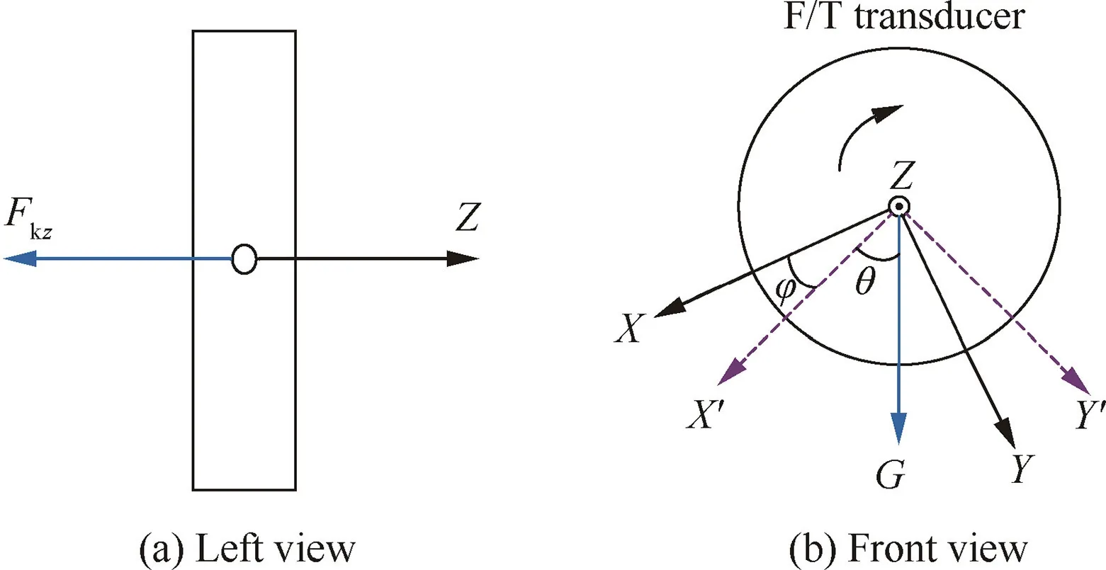
Fig. 1 Stress analysis of the transducer from different views.
It should be pointed out that the static calibration of the F/T transducer is divided into the following two steps:zero drift compensation and gravity compensation.
2.2. Zero drift compensation
When the transducer installed on the robot end-effector is in a no-load state, the value of F/T data obtained may not approach to zero, but is affected by the temperature, voltage,and environment,thereby resulting in a subsequent calculation deviation.The stress analysis of the transducer is illustrated in Fig. 1 when the robot is in the home position, where G is the load of the transducer; X, Y, and Z are the theoretical transducer frame{S},while X′and Y′are the real transducer frame considering the installation error. Note that φ is the installation angle of the F/T transducer, and θ is the rotation angle of the robot. When the robot is in the home position and the X direction of the F/T transducer is sticking straight down,φ=0.
According to the stress analysis and the related literature39,40, the forces are given by

where GSis the gravity of the transducer, GTis the gravity of the fixture and the workpiece, and Fkzis the pre-tightening force of bolts and always points to the-Z direction of the sensor coordinate frame. Fkxand Fkyare the zero drift forces of the transducer. Frx, Fry, and Frzare the inertia forces of three different directions, respectively.
Therefore, the results of zero drift compensation are obtained as follows:

where i=x,y,z.(Fci)is the array of forces after zero drift compensation.
2.3. Gravity compensation
When the robot is in different positions and orientations, the weight of the fixture is heavy enough,and the distance between the center of gravity and the transducer frame cannot be negligible, which will affect measurement results significantly.Therefore, it is necessary to perform gravity compensation on measured F/T values.
Fig.2 is the schematic diagram of robotic belt grinding of a workpiece with force control technology, and the coordinate frames of the robotic belt grinding system are defined accordingly. Since the transducer is installed on the robot endeffector, thus the orientation of the robot can be treated as the orientation of the transducer whether the robot moves or not. Similarly, the quaternion of the robot end-effector is also considered as the quaternion of the transducer.

Fig. 2 Schematic diagram of robotic belt grinding.
In Fig.2,{B}is the robot base coordinate frame,{S}is the F/T transducer coordinate frame, {T} is the grinding machine coordinate frame,{Tool0}is the robot end-effector coordinate frame, and {W} is the workpiece coordinate frame.
The quaternion of the transducer is (q1, q2, q3, q4), from which the TCP is relative to {B} and should be transformed into a rotation matrix R as

The transformation matrix from {Tool0} to {B} is calculated as

It should be recognized that the rotation deviation of the transducer along the -Z axis in the process of actual installation exists, and the deviation angle is θ. The distance between the origins of {S} and {Tool0} is h, and then the transformation matrix from {S} to {Tool0} is

Therefore, the transformation matrix from {S} to {B} can be calculated as
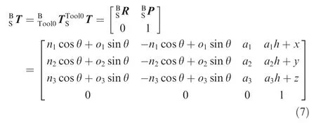
Note that gravity compensation should be in {S} of the transducer, and the result of any position and orientation of the robot is calculated as

In the process of robotic belt grinding of workpieces, such as turbine blades, the grinding force should be relative to {T}.As illustrated in Fig.3,the grinding force is defined in{T},and finally the constant force control technology in the process of robotic belt grinding can be achieved.
The grinding force satisfies the following equation:

where Fais the axial grinding force, Ftis the tangential grinding force, and Fnis the normal grinding force.
Therefore,{T}can be expressed by the orientation(q1T,q2T,q3T,q4T)and position(xT,yT,zT)in{B}.Then,the transformation matrix from {B} to {T} is given by

Finally, the compensation result of the force in {T} can be calculated as

3.Hybrid force-position control strategy in robotic belt grinding
The dynamics of a robotic system has been well studied in the literature.41If the manipulator interacts with the environment,it is convenient to describe its dynamics in an m-dimensional operational space where manipulation tasks are naturally specified. Neglecting the effects of joint friction, backlash and elasticity,and actuator dynamics,the equations of motion can be written in the following form:

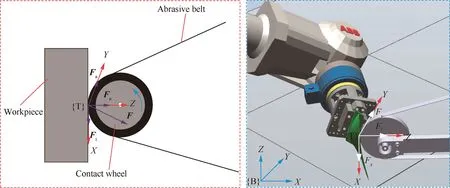
Fig. 3 Distribution of the grinding force in the process of robotic belt grinding.

The hybrid force-position control strategy, which can be divided into joint torque control and joint position control,was firstly proposed by Mason42and Raibert and Craig.43Since most industrial robots are based on joint position control, therefore, in our research, this method is selected to realize force tracking control in robotic belt grinding with a constant force. In order to eliminate a larger force deviation and acquire more desired output force,the PI controller is utilized in the force control law, while the PD controller is adopted in the position control law to improve the system response speed and stability. Then, it could satisfy the complexity and diversity of the robotic belt grinding system with the PI/PD and hybrid force-position control method.
A typical task for a robot manipulator in contact with the environment can be prescribed in terms of a position set point Xdand a force set point Fd.It can be recognized that,in general,a simultaneous achievement of both set points is not guaranteed.A viable strategy is to adopt the parallel controlapproach,which is especially effective in the case of inaccurate contact modeling.The keyfeature is to havea force control loop working in parallel to a position control loop along each task space direction.The logical conflict between the two loops is managed by imposing dominance of the force control action over the position one.
A hybrid force-position control method based on position PD force, gravity compensation, desired force feedforward,and force PI control is applied in our robotic belt grinding system of aero-engine blades. Then we can get

where Δxdis the position error, Δf is the force error, kppand kpdare the feedback coefficients of PD position control, kfpand kfiare the feedback coefficients of PI force control, and t is the machining time.
The process of the PI/PD and hybrid force-position control strategy is shown in Fig. 4, in which all the control variables are transformed into the joint displacement style. Firstly, by the constraints or normal direction estimation method, both the selection matrix S and I-S can be calculated to determine the choice of position control and the direction of force control. Position control and force control are adopted to the Xand Z axes of the tool frame, which keeps the normal force and X position stable to ensure the stability of the robotic abrasive belt grinding process. For the force control law, a more desired force F′dis obtained by selecting the PI controller according to the desired force Fd, and then it is transformed into displacement Xfand velocityin the Cartesian space with a kinematics model. For the position control law, the PD controller is adopted to improve the system response speed and stability, and then the outputsandare obtained according to the desired inputs Xdand.Thus,the force control outputs Xfandare superposed with the position control outputs Xpand,and then the superposed output Xeis converted into joints θcandby inverse kinematics to control the robot movement. In addition, position and force feedbacks,including signal conditioning and gravity compensation, are utilized to form a closed loop force control to obtain a better robotic grinding effect.
In Fig.4,Xe,,andare the displacement,velocity,and acceleration of the actual tool Cartesian space, respectively; S is the diagonal matrix which is decided by the constraint;Fhis the force measured by the F/T transducer; d and w are the machining depth and width of the workpiece, respectively;Fmis the machining force; Fci(Fcx, Fcy, Fcz) is the force after zero drift compensation,and Fi0(Fx0,Fy0,Fz0)is the force after gravity compensation.
The position control mode of the Cartesian space is used in our robotic belt grinding system, and the control method is listed below:


Fig. 4 Principle of the PI/PD and hybrid force-position control strategy.

Fig. 5 Force control process in robotic belt grinding.
where Xccan be translated to the joint angular displacement θcby inverse kinematics. Xc, Xp, and others are six-dimensional vectors.
In this paper, a method of hybrid force-position control combined with PI/PD control is applied in an actual robotic belt grinding process. Most importantly, the process grinding force can be remained constant relatively, and the depth of grinding (namely, the Z offset) can also be set as a fixed value in theory. In Fig. 5, the grinding force is changed into the reference force adaptively with the force control strategy proposed by adjusting the real-time robot position. Particularly,f1(F, Z), f2(F, Z), and f3(F, Z) are the curves about the relationships between the grinding force and the Z offset of the robot with less-grinding, perfect grinding, and over-grinding,respectively. When the robot position is located in Z1or Z3,the corresponding curve point a or c, namely the actual force f1(F1, Z1) or f3(F3, Z3), would be increased or decreased to positon Z2of the corresponding curve point b, namely f2(F2,Z2), in order to achieve a surface consistency of the machined workpiece by employing the presented force control technology.
Correspondingly, the grinding process can be divided into three stages: less-contact, in-contact, and over-contact. Thus,in Fig. 6, path planning also consists of three phrases: start phrase (A-C phrase), process phrase (C-D2 phrase), and end phrase (D2-E), in which the robot velocity keeps constant,where points A, B, C, D1, D2, and E are the path programming points, respectively. In this way, a sudden change in the force can be reduced when the workpiece gets in touch with the abrasive belt at the beginning.


Fig. 6 Path planning with a constant grinding force.
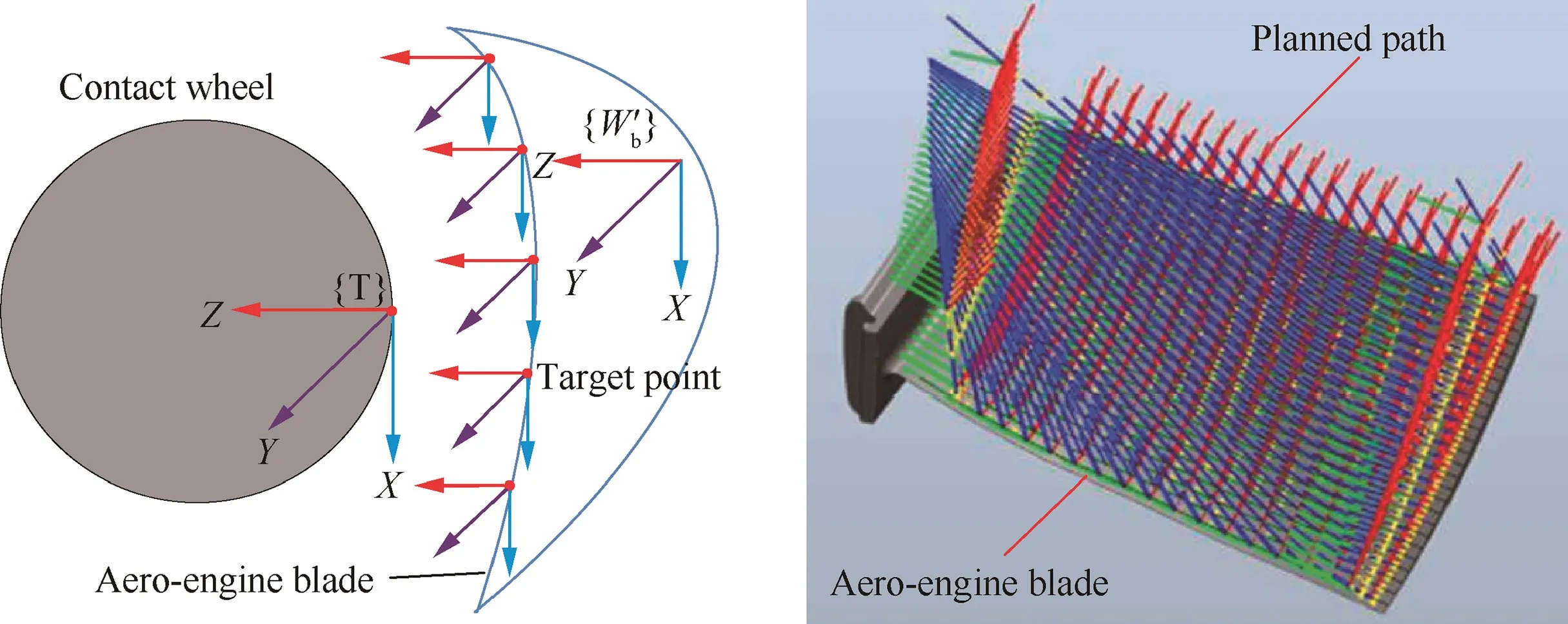
Fig. 7 Specific process of robotic belt grinding with an aero-engine blade.

Fig. 8 Force and position controls on the Z and X axes with path planning.

Fig. 9 Experimental setup of force control in the robot grinding system.
4. Experimental procedures
The experimental setup of the force control-based robotic belt grinding system is divided into two parts: hardware layer and software layer.
4.1. Experimental setup
Fig. 9 illustrates the experimental setup of force control in the robotic abrasive belt grinding system. Tests are conducted using a six-degree-of-freedom ABB robot (IBR4400-60/1.96)with a load capacity of 60 kg, a scope of work for 1.96 m,and a repeat positioning accuracy of 0.19 mm. A transducer(ATI Omega160) is installed on the robot end-effector with a weight of 3.72 kg, and detailed parameters are listed in Table 144. The DAQ device is composed of an NI PXle-4492 card and an NI PXle-1073 chassis.
The belt grinding machine self-developed is set in a horizontal position so that the forces measured correspond directly to the belt grinding forces. According to the robotic grinding technique45,46, in order to obtain a better grinding effect, the robotic working condition is as follows:the cylindrical contact wheel with dimensions of 25 mm in width and 180 mm in diameter is mainly composed of aluminum as the core material and elastic rubber as the out layer which has an average hardness of 15-20 HRC;the material of the abrasive grains on belts(GXK51-P type)is aluminum oxide with an average grain size of 80 μm;the tangential speed of the contact wheel is kept constant at 12.56 m/s;the work(robot velocity)speed is 50 mm/s.

Table 1 Detailed parameters of the Omega160 transducer.

Fig. 10 RFC software interface and three layers of the robotic belt grinding system.
4.2. Software setup
In order to receive the voltage signal and transform it to force information, the Robot Force Control (RFC) software, as shown in Fig.10(a),is developed to show and monitor results.Fig.10(b)shows the architecture of the RFC software which is divided into three layers: a force control GUI layer (RFC), a low-level communication layer (OPC Server), and a RAPID layer (RobotStudio). The OPC Server is chosen as the lowlevel communication mode between the robotic belt grinding system and the NI DAQ device system.When the robot moves along the planned path,the quaternion of the robot TCP in the RAPID can be transmitted to the RFC, and then the calculated force is compared with the reference force. If the calculated force is greater or smaller than the reference force, the corresponding robot motion information can be calculated and returned to the RAPID. Next, the robot will be driven in the specified path until the calculated force equals to the reference force. Therefore, the robotic belt grinding process of a workpiece with a constant force can be finally achieved.
5. Results and discussion
5.1. Compensation results
It should be noted that the inertia force Fri(Frx,Fry,and Frz)in Eq.(2)is quite small relative to the grinding force,and can be ignored due to the uniform motion of the robot in the grinding process. Thus Eq. (2) can be simplified as

When the robot is in the home position, the gravity(GS=36.6 N) can be measured by a specific algorithm.According to Eq. (15), the zero drifts of X and Y directions can be identified when the robot is in the home position(equally, the X direction of the transducer is vertical down),and the zero drift of the Z direction can also be obtained when the robot is rotated by 90°(equally,the Y direction of the transducer is vertical down).Finally,the zero drift values can be calculated as Fkx=-105.6 N,Fky=75.8 N,and Fkz=394.7 N,respectively.
When the fixture and the test workpiece are installed on the transducer,the gravity can be calibrated as GS+GT=106 N,and then Eq. (15) is rewritten as

After completing zero drift compensation and gravity compensation, Eq. (8) can be rewritten as
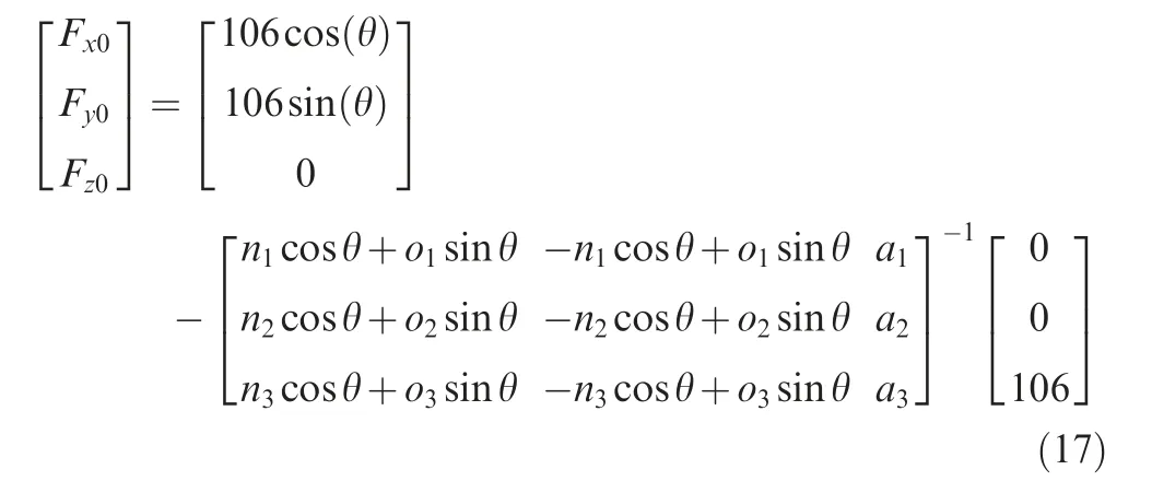

Fig. 11 Different orientations of the robot and the transducer.

Table 2 Compensated results of force at different orientations of the robot.

Fig. 12 Comparison of the compensated forces when the robot is in different states.
Fig. 11 shows the different orientations of the robot and the transducer, and the results of compensated force in accordance with Eq. (17) are listed in Table 2. It is revealed that the compensated forces are rather small, even approaching to zero when the robot is in a static state with different orientations. Therefore, the calibration algorithm of force can be applied to the robotic belt grinding system correctly and precisely.
Fig.12(a)shows that when the robot is in a static state,the compensated force fluctuates slightly in any position. In contrast, when the robot moves with different axis rotations in a velocity of 50 mm/s, the compensated force, as shown in Fig.12(b),fluctuates heavily in the range of-5 N to 5 N owing to the influences of the inertia force, random error, and measurement error, and this variation of force is decided by the whole robotic grinding environment.
5.2.Applications in robotic belt grinding of a test workpiece and an aero-engine blade
In the robotic abrasive belt grinding system,Eq.(11)is rewritten as the following equation:

For the application of robotic abrasive belt grinding of a test workpiece,Fig.13 compares the monitored grinding forces without and with force control in the conditions of the same planned robot path and grinding parameters. It is obviously observed in Fig.13(a)that the grinding normal force Fzfluctuates greatly from -35 N to-2N. After the force control technology is applied to the grinding system, it is revealed in Fig. 13(b) that Fzstabilizes at the reference force which is set as 30 N, the average fluctuation is relatively small (within 5 N) which contains 32 grinding paths, and the normal grinding force fluctuations of about 5 paths are greater than 5 N owing to the control error of the whole robotic belt grinding system.This indicates that a more stable normal grinding force(Fz) can be obtained with force control.
Fig.14 shows robot TCP position tracking of the test workpiece without and with positon control. It is found that the Z positon has been greatly changed after the constant force control technology applied from 4 paths. Force and position controls are adopted in the Z and X directions related to the tool coordinates frame, respectively. Therefore, the TCP position should be kept constant in the X direction at each grinding path to ensure grinding stability and consistency. The black line of Fig. 14(b) is the real trajectory, while the green one is the expected value, and we can find that the real trajectory is close to the expected one largely,which can verify the effectiveness of the position control method.
Fig. 15 further compares the grinding effects of the test workpiece which is made of Ti-6Al-4V with dimensions of 200 mm×100 mm×20 mm. Obvious chatter vibration on the workpiece is observed during the belt grinding process without force control. In contrast, the surface quality of the workpiece has been greatly improved with force control.Fig. 16 compares the surface roughness values measured by an SJ210 portable surface roughness tester of Mitutoyo at 24 points on the workpiece (three times for each point) without and with force control. It has been found that the average Ra value with force control can reach 0.355 μm, which is reduced by half from the average value of 0.774 μm without force control.
Fig. 17 further illustrates the application of the force control technology during robotic belt grinding of a blade which is made of Ti-6Al-4V with dimensions of 195 mm×123 mm×2 mm. It is observed that the grinding forces during the entire grinding process show significant differences: the grinding normal forces fluctuate greatly from-20 N to -140 N and -10 N to -70 N at the blade concave and convex surfaces without force control, respectively, while the values stabilize in the ranges of -39 N to -55 N and-37 N to -58 N at the blade concave and convex surfaces once the force control is applied,which all approach to the reference force set as 40 N. Furthermore, the force in Fig. 17(a)fluctuates more heavily than that in Fig.17(c)owing to the fact that the curvature of the concave surface varies more greatly than that of the convex surface. Specifically, at any one surface,phrase 1 or phrase 3 relative to phrase 2 or phrase 4 experiences a greater curvature variance. In contrast, the force control technology well solves this problem, bringing more stable force fluctuation at 40 N,even at the blade surfaces with a great curvature, as shown in Fig. 17(b) and (d).
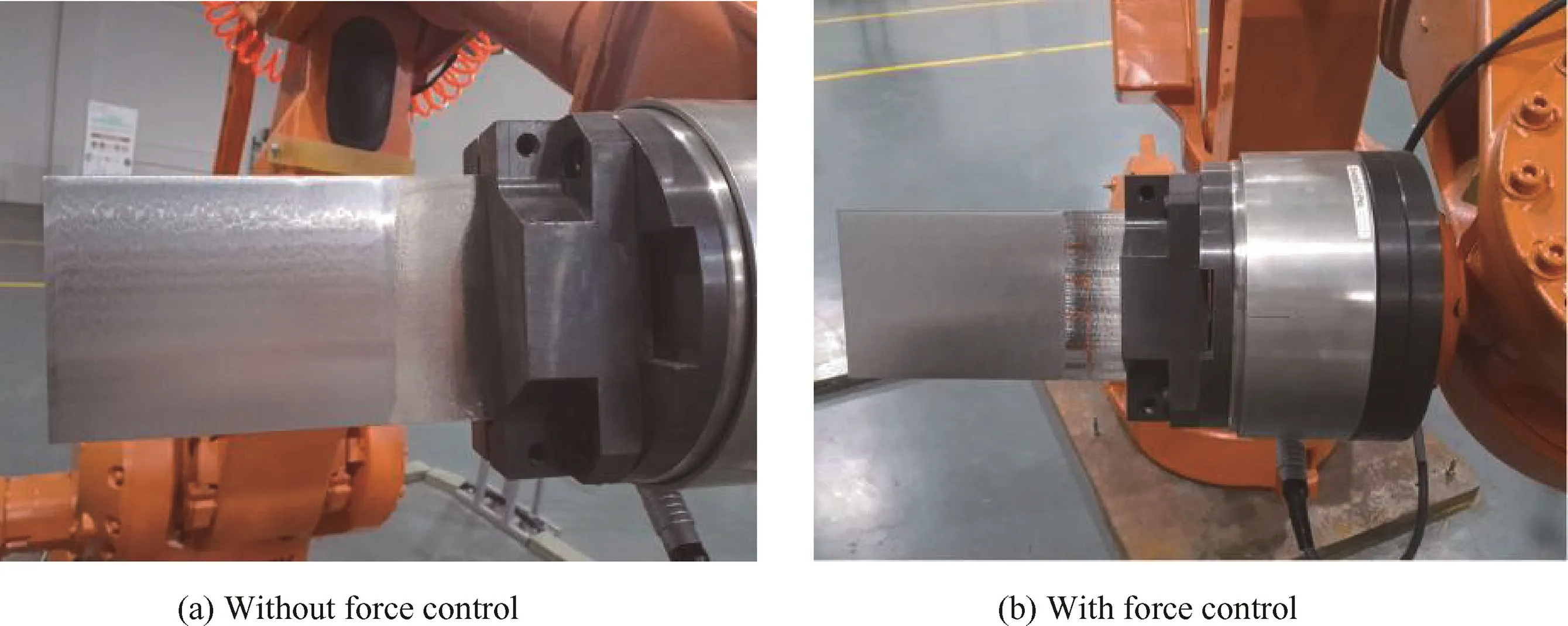
Fig. 15 Comparison of grinding effects of the test workpiece under grinding parameters (vr=50 mm/s, vc=12.56 m/s).
The magnitude of the force fluctuation determines the quality and consistency of the machined blade surface. It is observed in Fig. 18(a) and (c) of the concave and convex surfaces of the blade that a great fluctuation of grinding forces in the condition without force control results in obvious grinding marks,as well as the phenomena of over-and under-grinding.Conversely,the surface quality has a great improvement when the force control technology is applied to the robotic belt grinding system,as shown in Fig.18(b)and(d)of the concave and convex surfaces of the blade. This is also reflected in the improvement of surface roughness. The average values of Ra at the concave and convex surfaces of the blade without and with force control are 1.085 μm and 1.083 μm, 0.375 μm and 0.283 μm, respectively. Of course, the grinding effect is also observed from the surface profiles of the blade, as shown in Fig. 18(e) and (f), where green is qualified and red is out of scope. Therefore, constant-force grinding is proven to be of great practicality and effectiveness to robotic abrasive belt grinding of complex blades.
5.3. Analysis of F/T transducer accuracy
5.3.1. Effect of the robotic belt grinding system
The hardware device of the robotic belt grinding system contains an ABB 4400 robot, an ATI Omega 160 transducer, an NI DAQ device, and a grinding machine. Since the measurement error may be caused by the hardware device, as well as the interaction between them, therefore, factors affecting results are analyzed.
During the robotic belt grinding process, the position change of the robot moving along the planned grinding path is actually larger than its orientation. Additionally, the robot positioning error is greater than its orientation error.47Thus,robot errors caused by its motion, as well as the inertia force,cannot be avoided.As shown in Fig.19,the acceleration in the robotic grinding path with a constant velocity of 50 mm/s is relatively smaller than that in the transition path. Therefore,it is believed that the influence of the inertia force could be neglected during an effective grinding contact process.
The pseudo differential input of six channels is applied in the NI DAQ device to reduce the signal noise and improve the measurement accuracy, and thus external signal shielding can be ensured in the whole signal acquisition circuit. Therefore, the obtained voltage signal can be regarded as the real signal without signal distortion and delay, and then it is considered that it cannot exert effects on results.
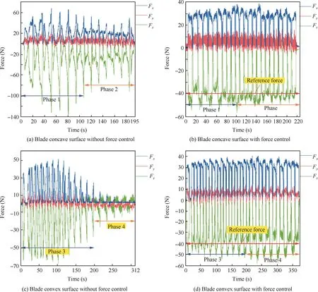
Fig. 17 Force monitoring during robotic belt grinding under grinding parameters (vr=50 mm/s, vc=12.56 m/s).
The grinding machine is specially designed to be applied in robotic grinding of complex parts,and therefore,it can be well adapted to complex blades. However, the chatter, caused by the work of the machine, cannot be neglected in the process of grinding,and the decentration48and chatter49of the contact wheel also cause an influence on results.
5.3.2. Effect of external environment
The typical gain error introduced by the over temperature for F/T transducers with hardware temperature compensation is 1% with ±25°C.38These changes in sensitivity are independent of a transducer’s rated accuracy at room temperature,whereas the drift error caused by temperature is not compensated and varies with each transducer. Therefore, this error caused by temperature also brings an effect on results.
The steady-state error of the force feedback mainly comes from two parts:one part is caused by the weights of the clamping and the workpiece,and the other is the zero drift of the F/T transducer. Usually, the former is a constant, while the latter changes slowly. Especially, it is obvious when the machine is power-on. Therefore, under normal circumstances, the steady-state error should be compensated to make the sensor in a ‘‘zero” force state before robotic grinding.50When the transducer is mounted on the robot end-effector and the robot is in the servo state, the reflected random disturbance signal is large slightly due to the influence of the servo system. Most importantly, this random error cannot be removed effectively in the process of robotic grinding and will affect results.
6. Conclusions
In this paper, a kind of novel force control method, including force calculation, zero drift compensation, gravity compensation,and a hybrid force-position control and PI/PD force control algorithm, is proposed to be applied in the robotic abrasive belt grinding process. In order to test the practicality and validity of the force control technology,both a test workpiece (simple part) and an aero-engine blade (complex part)are selected for grinding in the same grinding path and parameters without and with force control, respectively. The following conclusions are achieved:
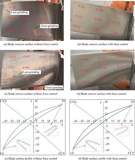
Fig. 18 Comparison of grinding effects under grinding parameters (vr=50 mm/s, vc=12.56 m/s).

Fig. 19 Acceleration of robotic grinding of a blade with force control.
(1) Owing to the influences of both the robotic inertia force and the F/T transducer, the compensated force within the range of -5 N to 5 N when the robot moves at a speed of 50 mm/s is found to be much greater than that of -1 N to 1 N in the static state of the robot.
(2) Compared with the normal force in the process of robotic belt grinding of the test workpiece without force control, the controlled grinding normal force more approaches to the reference force which is set as 30 N.The corresponding surface roughness Ra is reduced by half from an average value of 0.744 μm without force control to 0.335 μm with force control.
(3) Like grinding of the test workpiece,the controlled grinding normal force in the process of robotic belt grinding of the aero-engine blade is also found to be more approaching to the reference force which is set as 40 N than the uncontrolled normal force. The corresponding surface roughness Ra is reduced significantly from average values of 1.085 μm and 1.083 μm without force control to 0.375 μm and 0.283 μm with force control at the concave and convex surfaces of the blade, respectively.
(4) The above results imply the advantages of the force control technology to the great improvement on the surface machining consistency and profile accuracy. Relative to abrasive belt grinding of simple parts, it is deduced that the force control technology is more needed in robotic belt grinding of complex parts to achieve desired grinding effects.
Acknowledgements
National Nature Science Foundation of China(Nos.51675394 and 51375196),National Key Research and Development Program of China(No.2017YFB1303404),State Key Laboratory of Digital Manufacturing Equipment and Technology of China (No. DMETKF2018018), Fundamental Research Funds for the Central Universities of China (No.2017II33GX),and the Key R&D Program of Jiangsu Province(No. BE2015005).
Appendix A. Supplementary data
Supplementary data associated with this article can be found,in the online version, at https://doi.org/10.1016/j.cja.2019.01.023.
 CHINESE JOURNAL OF AERONAUTICS2019年10期
- CHINESE JOURNAL OF AERONAUTICS的其它文章
- Design and analysis of a hypersonic inlet with an integrated bump/forebody
- High precision attitude dynamic tracking control of a moving space target
- Guidance laws for attacking defended target
- Closed form algorithm of double-satellite TDOA+AOA localization based on WGS-84 model
- Effects of yaw-roll coupling ratio on the lateraldirectional departure prediction and restraint
- Experimental study of single-row chevron-jet impingement heat transfer on concave surfaces with different curvatures
