
Phrenic nerve displacement by intrapericardial balloon inflation during epicardial ablation of ventricular tachycardia:Four case reports
2020-02-24 06:38:06
World Journal of Cardiology 2020年1期
Sergio Conti,Umberto Giordano,Giuseppe Sgarito,Department of Cardiology,Electrophysiology,Palermo 90127,Italy
Sergio Conti,Faculty of Medicine,University of Tor Vergata,Rome 00133,Italy
Vito Bonomo,Department of Cardiology,University of Palermo,Palermo 90127,Italy
Antonio Taormina,Department of Cardiology,University of Messina,Messina 98122,Italy
Abstract
Key words:Catheter ablation;Epicardial access;Myocarditis;Nonischemic cardiomyopathy;Ventricular tachycardia;Phrenic nerve;Case series
INTRODUCTION
Phrenic nerve (PN) injury is one of the recognized possible complications following catheter ablation procedures.Although uncommon,PN injury can result in permanent paralysis of the diaphragm.The symptoms of diaphragmatic palsies can vary from asymptomatic to cough,dyspnea,recurrent pneumonia,and severe respiratory dysfunction requiring mechanical ventilation.The severity of clinical presentation primarily depends upon the degree of PN injury and underlying lung capacity.PN injury has been reported after endocardial catheter ablation of atrial fibrillation[1],atrial tachycardia[2],inappropriate sinus tachycardia[3],left-sided accessory pathways[4],and epicardial ablation of ventricular tachycardia (VT)[5-7].In particular,the increasing number of epicardial VT ablations[8]could increase the risk of PN injury,given that the left PN is in direct contact with the epicardial surface.The course of the PN is usually determined by eliciting diaphragmatic contraction through high-voltage output pacing,and which can be viewed using one of the available 3D electroanatomical mapping (3D-EAM) systems[9].Different techniques for avoiding PN injury have been reported,including introduction of air and/or saline into the pericardial space,or introduction of a deflectable sheath as well as different types of large balloons[10].We have reported our single-center experience of epicardial VT ablation procedures,where the use of a valvuloplasty balloon catheter successfully prevented PN injury.
CASE PRESENTATION
Electrophysiologic study and catheter ablation
After informed consent was obtained,three patients underwent epicardial ablation for drug-refractory VT under general anesthesia.Intracardiac catheters were insertedviathe right and left femoral veins,and included a 6F decapolar catheter placed into the coronary sinus,a 6F quadripolar catheter placed into the right ventricular apex,a standard multipolar or a high-definition mapping catheter (LiveWire 2-2-2 or Advisor HD Grid,Abbott,Medical,United States),an ablation catheter,and an intracardiac echo probe (AcuNav,Siemens).Invasive blood pressure was monitored from the right femoral artery.The EnSite PrecisionTMelectroanatomical mapping system (Abbott Medical,United States) was used to create endo/epicardial geometries,substrates,and activation maps.Epicardial access was obtained by subxiphoid pericardial puncture,as described elsewhere[11].Once an epicardial map was obtained and the area of interest identified,a coronary angiogram was performed upon all patients in order to show the safety distance between the coronary arteries and the scar region.Then,in order to prevent PN injury,the course of the PN was identified by provoking diaphragmatic stimulation with high-output pacing from the distal electrode of the ablation catheter.The locations of PN capture were marked on the 3D-EAM.Considering the close relationship between the area of interest and the PN,we decided to displace the PN in order to increase its distance from the ablation catheter.We then obtained another epicardial access in order to insert a 12F introducer sheath with a hydrophilic coating (Sentrant,Medtronic) (Figure1A and B).In every case,an 18 mm × 40 mm percutaneous transluminal balloon aortic and pulmonic valvuloplasty catheter (Nucleus-X,Braun Medical) was inserted and inflated with saline solution to separate the PN from the epicardium (Figure2A and B).Finally,high-output pacing was repeated to reassess PN capture.Radiofrequency (RF) was delivered using a 3.5 mm open irrigated tip ablation catheter (FlexAbility SE,Abbott Medical,United States) and an Agilis EPI steerable epicardial sheath (Abbott Medical,United States).The energy setting was 40-50 w,43 °C maximum temperature,17 mL/min ablation catheter flow rate.Successful RF ablation was defined as the complete elimination of all LPs,and the inability to induce VTs with programmed stimulation.A final remap was performed to assess the complete elimination of LPs.After completion of RF delivery,the valvuloplasty balloon catheter was deflated and removed.PN capture was tested after ablation.Following the procedure,the absence of fluid in the pericardial space was confirmed by the intracardiac echo.
Patient 1
A 32-year-old woman with a prior history of myocarditis and a subcutaneous implantable cardioverter defibrillator (S-ICD) presented at the Emergency Department of our hospital after three syncope and S-ICD shocks.The 12-lead ECG showed a VT with a CL of 230 ms and right bundle inferior axis (RBIA) morphology(Figure3).Echocardiogram showed a normal LV ejection fraction (LVEF) of 55%.Coronary angiogram showed no significant coronary artery disease.Cardiac magnetic resonance imaging (MRI) showed an LVEF of 50%.Moreover,MRI showed intramural and transmural late-gadolinium enhancement (LGE) in the basal anterolateral LV wall and sub-epicardial LGE in the mid-basal lateral wall (Figure4).Electrophysiological (EP) study with 3D-EAM of the epicardium was performed as described above.In concordance with the MRI findings,we found a mid-basal lateral epicardial scar,and LPs were identified within the epicardial scar (Figure5A and B).After the angiogram,high-output pacing was performed to assess PN capture.The scar region was along the PN course (Figure6).Through the second epicardial access,we inserted another sheath and the valvuloplasty balloon in the epicardial space.Once the balloon was inflated in the epicardial space,high-output pacing was repeated without PN capture.RF was delivered along the scar region,aiming for complete LP elimination with no complications (Figure7).Once the lesion set was considered complete,the valvuloplasty balloon was deflated and removed.Programmed ventricular stimulation was performed up to three extrastimuli without induction of ventricular arrhythmia.No VT were reported to have recurred within the 2 years of follow-up.
Patient 2
A 56-year-old woman with no previous cardiac history presented to our Centre with a hemodynamically-tolerated VT with an RBIA morphology and CL 320 ms (Figure8).The VT was converted to sinus rhythm after an intravenous bolus of amiodarone.Transthoracic echocardiogram and coronary angiogram were both normal.However,the MRI showed a subepicardial scar in the basal lateral-posterolateral LV wall with LGE,which was compatible with myocarditis.During the EP study,the clinical VT was induced by programmed ventricular stimulation.At first,an endocardial ablation was attempted in the basal posterolateral LV,but it was unsuccessful.Therefore,we obtained epicardial access and,in concordance with the MRI findings,we found a basal posterolateral epicardial scar with LPs (Figure9).As per the protocol,we performed a coronary angiogram that showed enough distance between the coronary arteries and the scar.We observed PN capture along the scar,and LPs were located along its course.Following the same procedural steps,we inserted the second epicardial sheath and the balloon facing the PN.Once the balloon was inflated,an absence of PN was noted and all LPs could be targeted and eliminated.After successful RF delivery,the balloon was deflated and removed.Programmed ventricular stimulation demonstrated no acute VT inducibility,and no VT recurrences have been documented within the 1-year follow-up.

Figure1 Epicardial access to insert a 12F introducer sheath with a hydrophilic coating.A:Secondary epicardial access and introduction of 12F introducer sheath with a hydrophilic coating;B:Fluoroscopy image of the second wire and introducer in the epicardial space.
Patient 3
A 46-year-old man with a previous history of myocarditis and implantable cardioverter defibrillator implantation was admitted to our Emergency Department because of intense palpitations lasting up to 2 h.The 12-lead ECG showed a hemodynamically-tolerated VT with an RBIA morphology and CL 300 ms.After ineffective intravenous amiodarone,VT was converted to sinus rhythm through the use of a 200J DC shock.Echocardiography showed an LVEF of 50%,and a coronary angiogram showed normal coronary arteries.Cardiac MRI showed a subepicardial scar in the basal lateral LV wall with sub-epicardial LGE in the mid-basal anterolateral wall.An endo-epicardial substrate map revealed a scar in the mid-basal lateral and posterolateral LV wall,with LPs along the border zone of the mid-basal posterolateral scar and along the mid-basal lateral wall (Figure10).PN capture was documented along the scar and in the LP region.Once again,after obtaining secondary epicardial access,the balloon was inserted and positioned to avoid PN capture,and RF was delivered along the entire extension of the scar (Figure11).The final remap showed no more signs of LPs,and programmed ventricular stimulation showed no VT inducibility.The patient had not reported any VT recurrences at the time of the 9-mo follow-up.
Patient 4
A 66-year-old man with a previous history of ischemic cardiomyopathy,implantable cardioverter defibrillator,and previous endocardial VT ablation was admitted to our Centre because of several ICD therapies noted during the remote monitoring followup.The 12-lead ECG showed normal sinus rhythm.Echocardiography showed an LVEF of 30%,and a coronary angiogram did not show new coronary artery lesions.An epicardial substrate map revealed a scar in the infero-postero-lateral mid-basal LV wall,with LPs along the border zone of the scar (Figure12).PN capture was documented along the scar and in the LP region.The same approach was used to avoid PN injury (Figure13).After obtaining secondary epicardial access,the balloon was inserted and positioned in order to avoid PN capture.Two slightly different morphologies of VT were induced by ventricular programmed stimulation,and RF was delivered with VT termination (Figure14 and 15).The final remap showed no more LPs,and programmed ventricular stimulation showed no VT inducibility.The patient had not reported any VT recurrences at the time of the 3-mo follow-up.
DISCUSSION
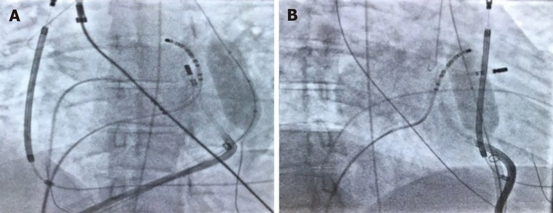
Figure2 Patient 1:The vascular balloon was inflated to displace the phrenic nerve.A:Right anterior oblique 30 degrees;B:Left anterior oblique 30 degrees.
PN injury is a recognized complication of catheter ablation procedures,and has been reported following ablation of atrial,supraventricular,and VT and with multiple ablation modalities including RF,cryoballoon ablation,and LASER[1-7].Particularly notable is the left PN that runs along the lateral LV wall before inserting in the diaphragm[12].Due to the left PN course and the increasing number of epicardial VT ablations,it will not be uncommon to deal with the potential risk of PN injury in the future.In order to avoid PN complications,a common precaution is to establish the proximity of the ablation catheter tip in relation to the PN course.This is typically performed using high-output pacing,and includes 3D tags into the EAM in order to create a visual representation of the distance between the tip of the ablation catheter and the PN course.However,ablation in an area close to the PN is sometimes necessary,and different techniques have been described to avoid PN injury,such as the introduction of air and/or saline into the pericardial space,or introduction of a second deflectable sheath and different types of large balloons.Table1 summarizes all cases reported in the literature of epicardial VT ablation,in which PN was displaced using various types of large balloons in the pericardial space.Buchet al[13]described the first case in 2007 in a 78-year-old patient with ischemic cardiomyopathy and drugrefractory VT originating from the epicardial posterosuperior aspect of the LV.They used an 18 mm × 40 mm dilatation catheter (Meditech,Boston Scientific) positioned close to the ablation tip obtaining PN displacement without complication[13].Biaseet al[10]reported a multicenter prospective comparison between methods for separating the PN from the epicardial surface.Interestingly,of the eight patients involved,the authors reported two cases of failure to prevent PN capture,and three cases of unsuccessful placement of the intrapericardial balloon.They found controlled “hydropneumopericardium” to be the best strategy for preventing PN injury during epicardial ablation[10].Kumar and colleagues reported the largest series.Five patients with nonischemic cardiomyopathy underwent epicardial VT ablation and effective PN displacement by using the vascular or the gastrointestinal balloon.The authors reported two complications among these patients,including a case of pleuropericardial fistula and moderate pericarditis,which was resolved after colchicine administration[14].One of the limitations of intrapericardial balloon placement is the inability to steer the balloon catheter,and the lack of support and stability.Fanet al[5]found that in order to overcome these limitations,the use of a steerable outer sheath to guide balloon placement was necessary for additional support and stability[5].In this case series,the use of intrapericardial balloon placement was safely and successfully used to increase the distance between the PN and the ablation target area,thus eliminating PN capture with high-output pacing.
CONCLUSION
PN injury can occur as one of the complications following epicardial VT ablation procedures,and may prevent successful ablation of these arrhythmias.Although few cases have been reported in the literature,PN displacement through the use of different types of large balloon catheters in the epicardial space to separate the PN from the ventricular epicardium during epicardial VT ablation seems to be feasible and reproducible,can help to avoid procedure-related morbidity,and can improve ablation success when performed in selected Centers and by experienced operators.
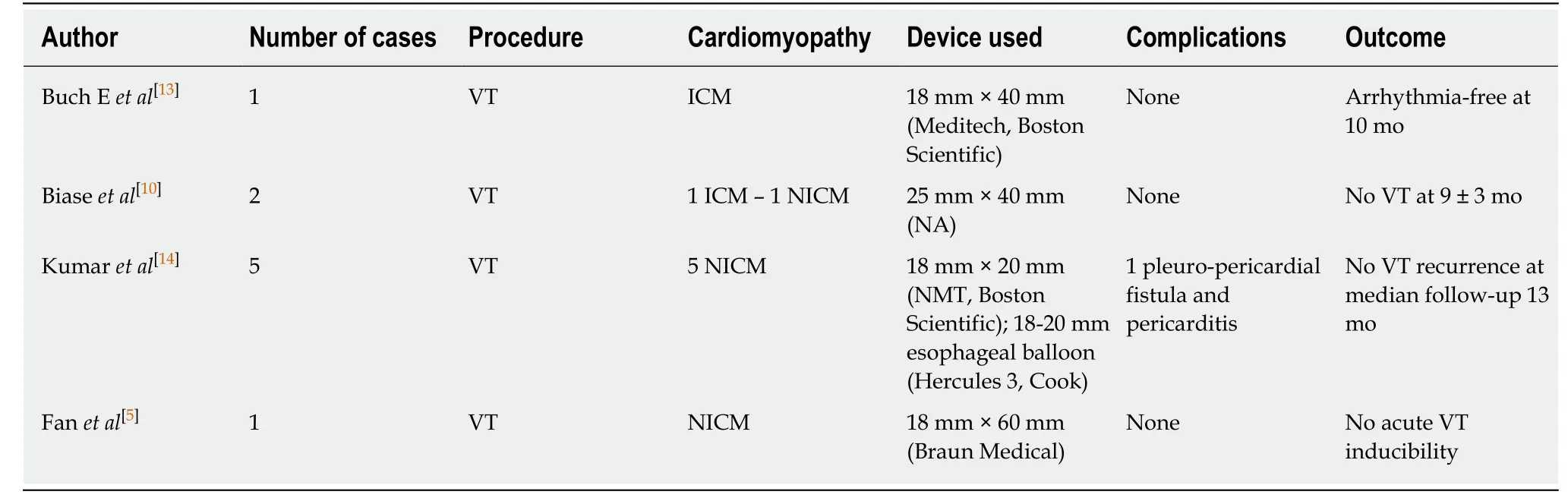
Table1 Reports published of various types of large balloons inserted into the pericardial space
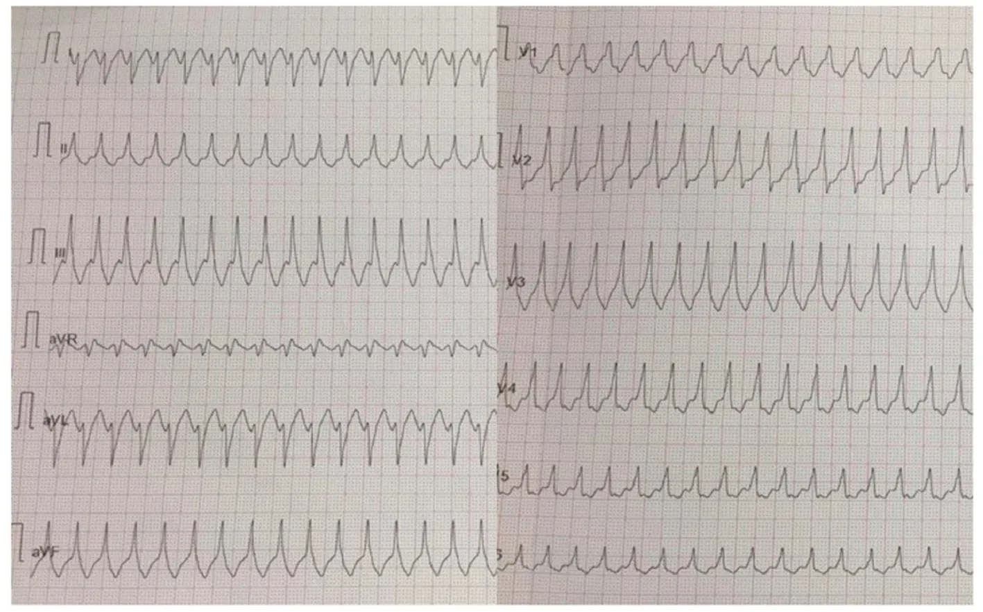
Figure3 Patient 1:12-lead ECG of ventricular tachycardia with a right bundle inferior axis morphology.
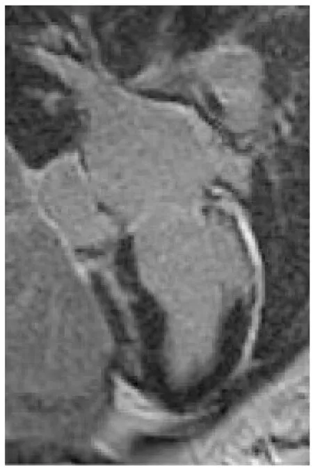
Figure4 Patient 1:Cardiac magnetic resonance imaging showing intramural and transmural late-gadolinium enhancement in the basal anterolateral left ventricular wall and sub-epicardial late-gadolinium enhancement in the mid-basal lateral wall.
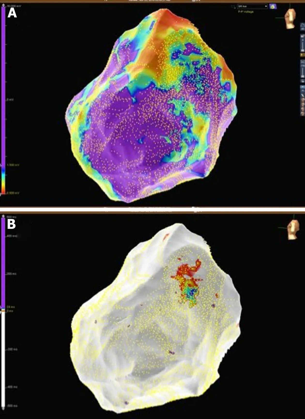
Figure5 Patient 1:Mid-basal lateral epicardial scar and late potentials were identified within the epicardial scar.A:Epicardial substrate map showing a basal lateral scar in the left ventricle;B:Epicardial late potentials map at the border zone of the epicardial scar.
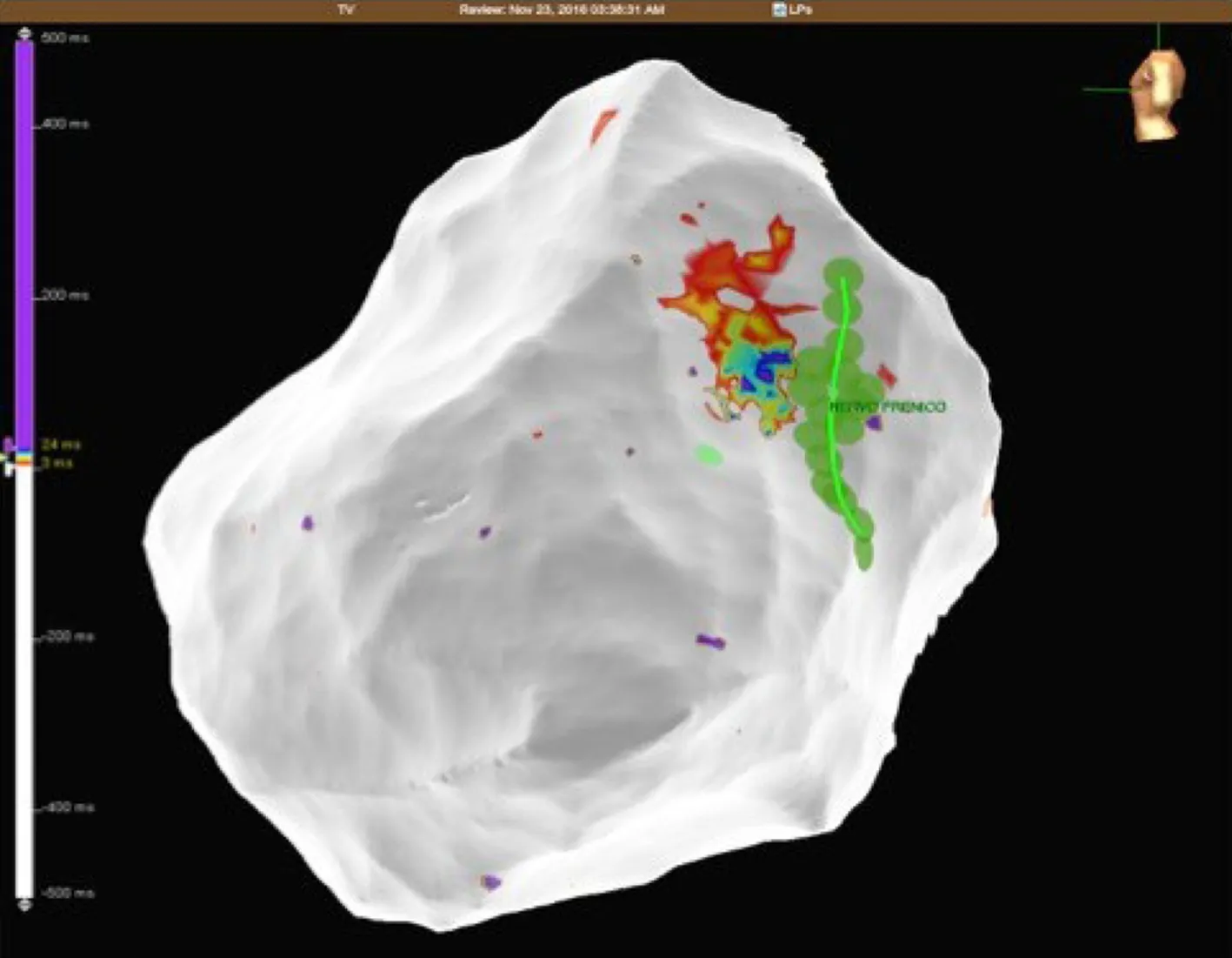
Figure6 Patient 1:Epicardial late potentials map of the basal lateral segment of the left ventricle.The phrenic nerve course is represented with green dots.
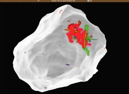
Figure7 Patient 1:The close relationship between radiofrequency ablation points (red dots) and the phrenic nerve course (green dots and line).
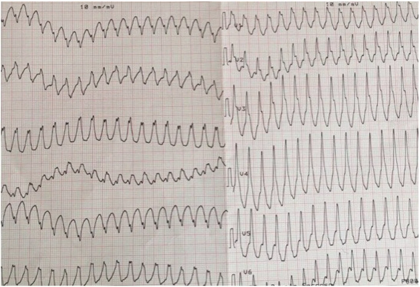
Figure8 Patient 2:12-lead ECG of ventricular tachycardia with a right bundle inferior axis morphology.
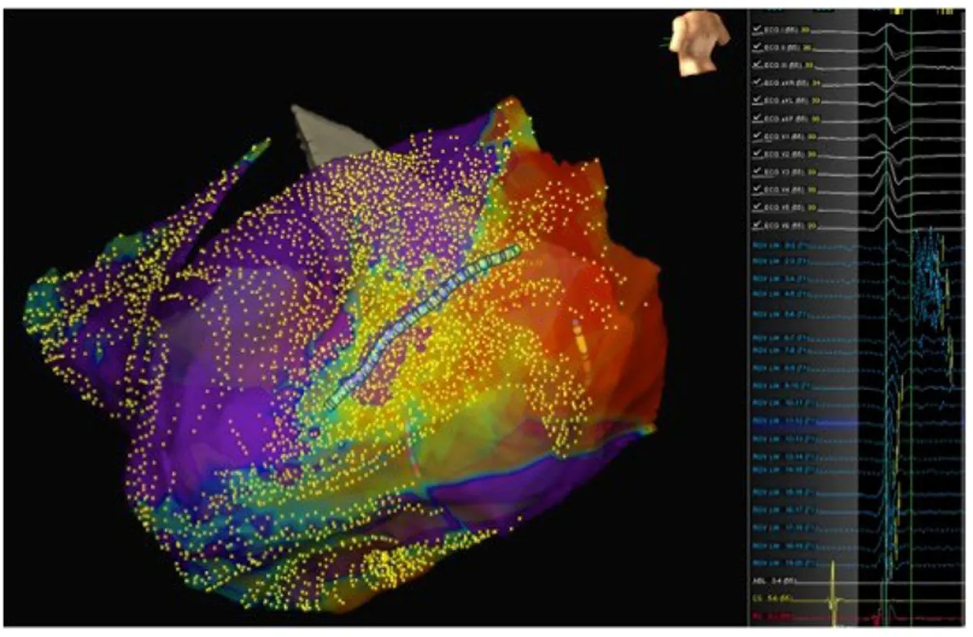
Figure9 Patient 2:A basal posterolateral epicardial scar with late potentials.Left panel:Epicardial activation map showing late potentials on the posterolateral left ventricular wall;Middle panel:Late potentials mapped using the LiveWire mapping catheter;Right panel:Epicardial substrate map showing the basal posterolateral scar.
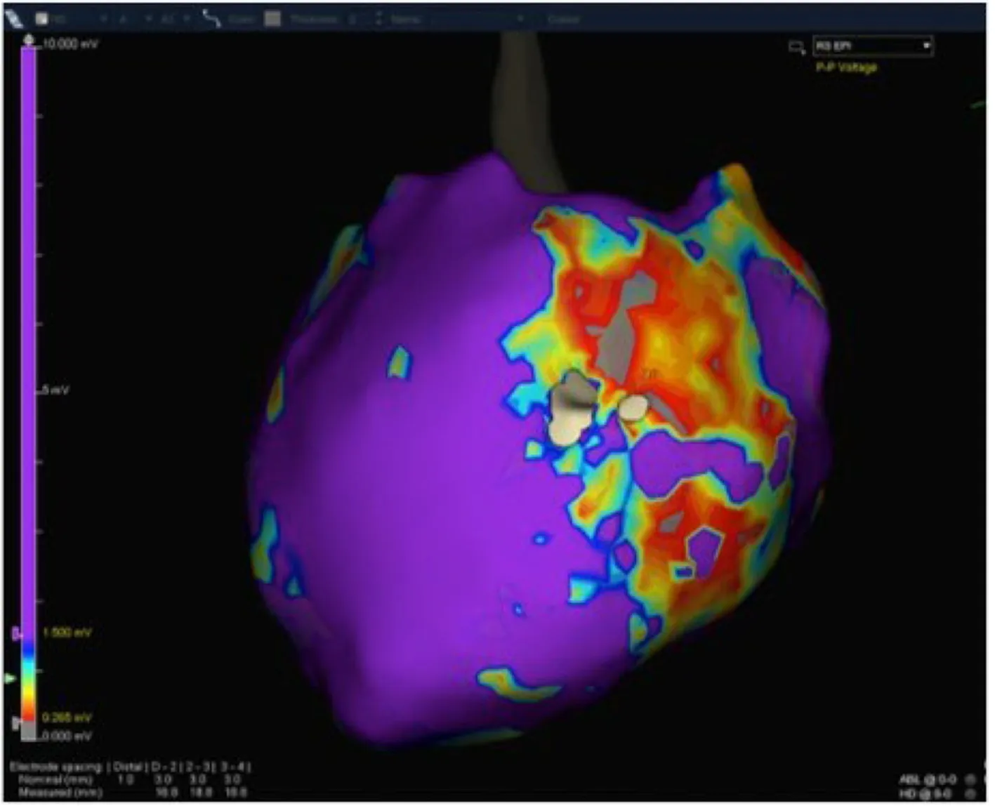
Figure10 Patient 3:Epicardial substrate map showing a wide scar extending from the basal lateral to the mid-posterolateral left ventricle wall.

Figure11 Patient 3:The vascular balloon has been inflated to displace the phrenic nerve (Left anterior oblique 35 degrees).
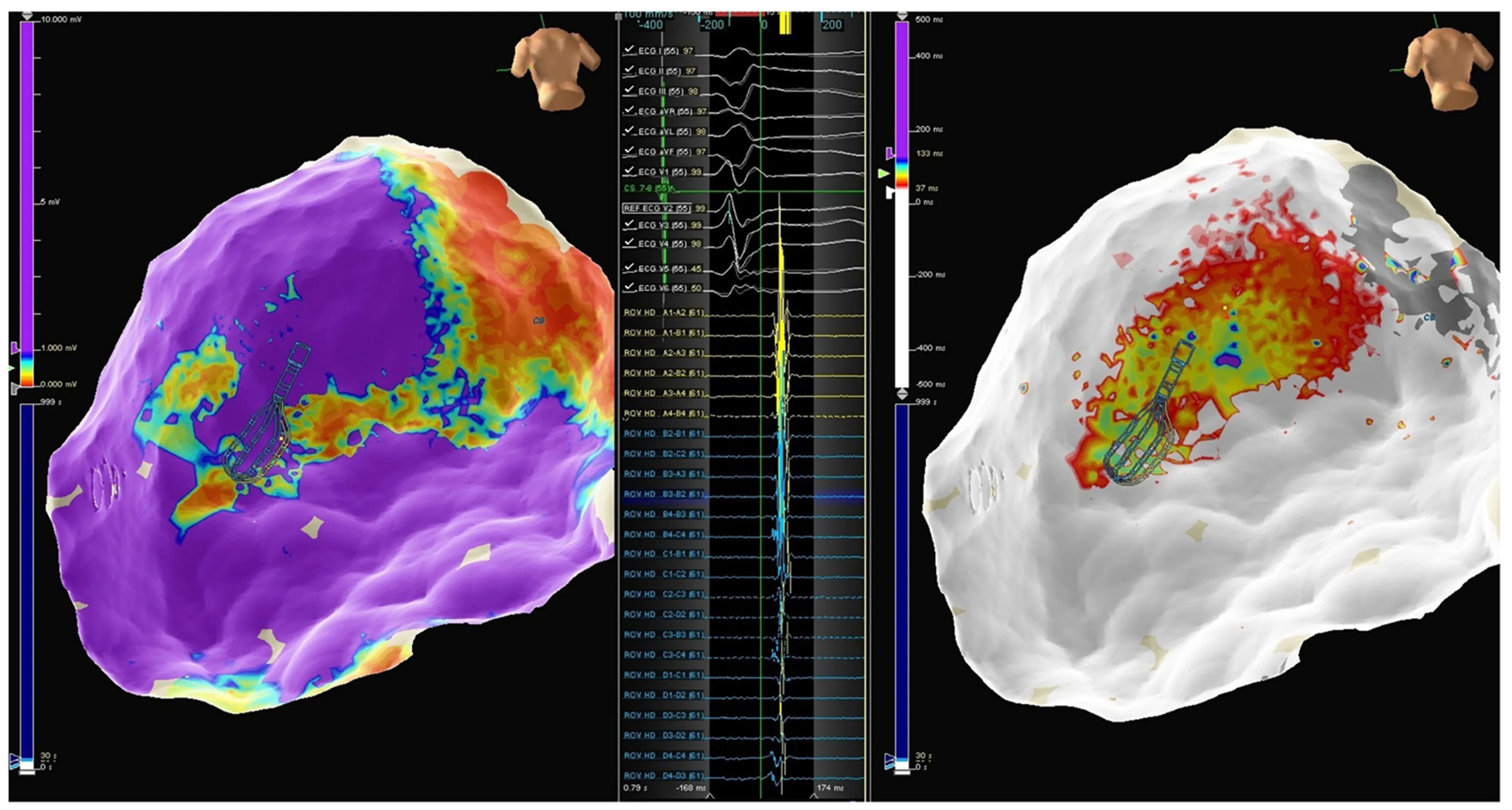
Figure12 Patient 4.Left panel:Epicardial map showing an infero-postero-lateral mid-basal scar;Middle panel:Late potentials mapped using the Advisor HD Grid;Right panel:Epicardial activation map in sinus rhythm showing late potential around the superior aspect of the scar.

Figure13 Patient 4:lnflation of the vascular balloon in the posterior epicardial space (Left anterior oblique 27 degrees).
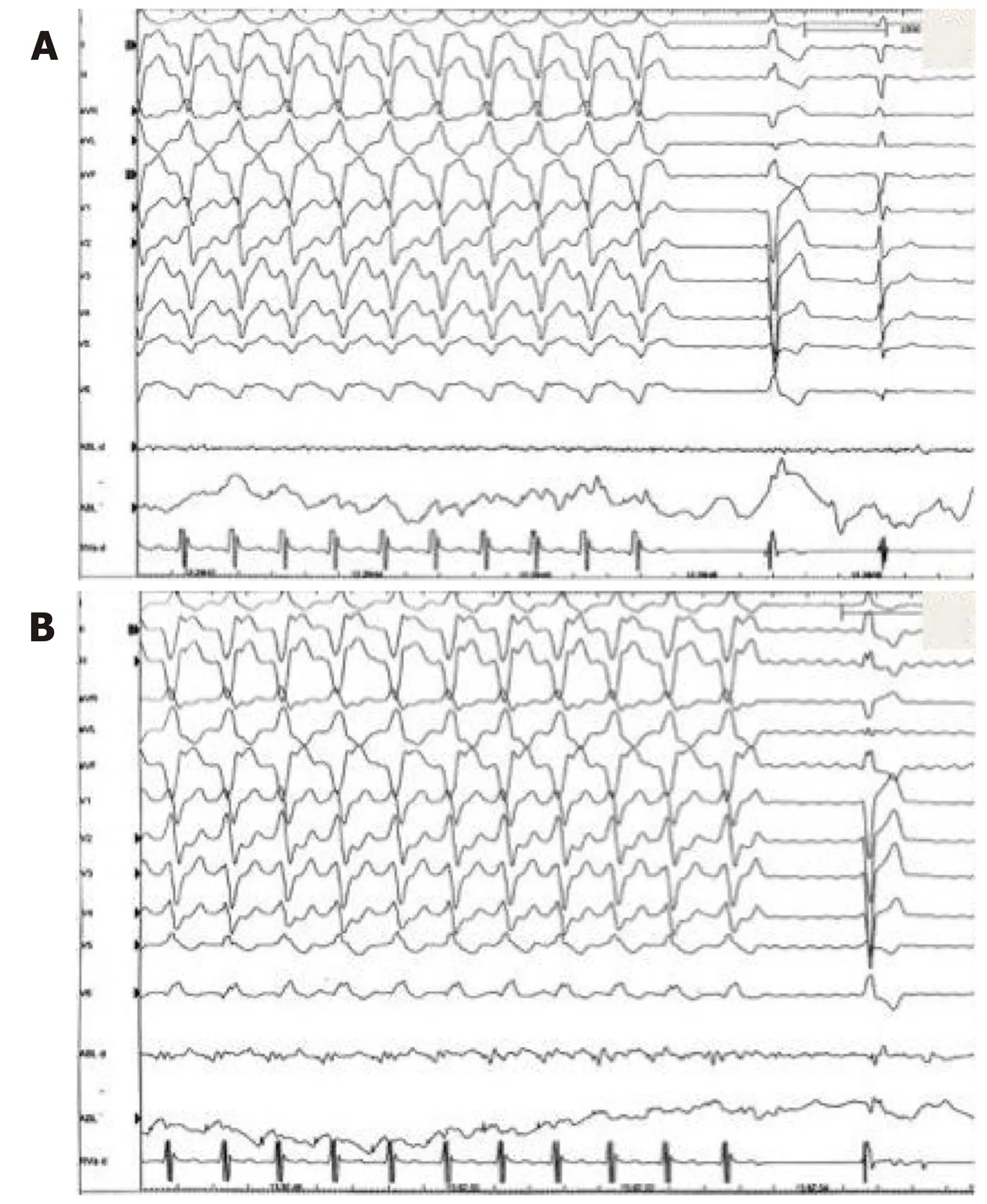
Figure14 Patient 4:Two slightly different morphologies of VT were induced by ventricular programmed stimulation and radiofrequency was delivered with VT termination.A:First morphology of VT termination during radiofrequency delivery in the infero-lateral region;B:Second morphology of VT termination during radiofrequency delivery in the more inferior region.VT:Ventricular tachycardia.
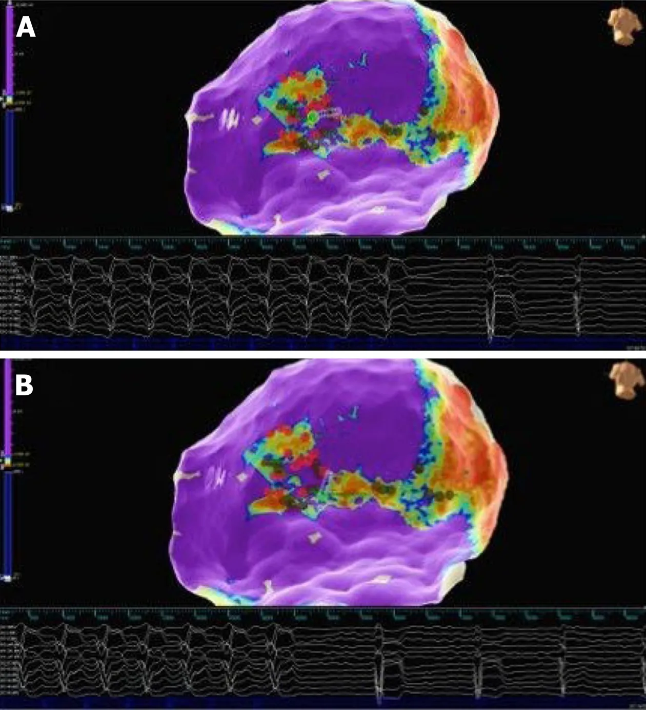
Figure15 Patient 4:Epicardial substrate map.Red dots are tags of phrenic nerve capture areas.Green dot on the tip of the ablation catheter represents the tag of VT termination.A:First morphology of VT termination during radiofrequency delivery in the infero-lateral region;B:Second morphology of VT termination during radiofrequency delivery in the more inferior region.VT:Ventricular tachycardia.
ACKNOWLEDGEMENTS
Special thanks for support to Michela Grande,BEng,Abbott,Milan,Italy.
 World Journal of Cardiology2020年1期
- World Journal of Cardiology的其它文章
- Salmonella typhimurium myopericarditis:A case report and review of literature
- Prognostic impact of body mass index on in-hospital bleeding complications after ST-segment elevation myocardial infarction
- lmpact of training specificity on exercise-induced cardiac troponin elevation in professional athletes:A pilot study
- Radial artery access site complications during cardiac procedures,clinical implications and potential solutions:The role of nitric oxide
- Diagnosis and treatment of heart failure with preserved left ventricular ejection fraction
- ls there a role for ischemia detection after an acute myocardial infarction?