
Structure Optimization of a Horizontal Gas-Solid Rapid Separation Device
2020-04-18 10:47:48AnXiaoxiFanJunfengTianYuanyuQiaoYingyunZongPeijie
中國煉油與石油化工 2020年1期
An Xiaoxi; Fan Junfeng; Tian Yuanyu; Qiao Yingyun; Zong Peijie
(1. Shandong University of Science and Technology, Qingdao 266510;2. China University of Petroleum (Huadong), Qingdao 266555)
Abstract: To meet the requirements for fast and efficient gas-solid separation at the outlet of a gas-solid concurrent downflow fluidized bed (downer), a new horizontal gas-solid rapid separator was designed based on the joint action of centrifugal and inertial forces. Under the same experimental conditions, a fluid catalytic cracking (FCC) catalyst was used as the material (with a particle density of 1 500 kg/m3 and a mean particle size of 45.8 μm) to experimentally investigate the effects of the insertion length of gas outlet pipe, the bypass cylinder, the gas outlet direction, and the secondary separation structure on the separator performance. The results showed that with an inlet gas flow rate of 14.5 m/s and a gas phase solid content of 60―835 g/m3, the downer system achieved a gas-solid separation efficiency of above 99.5%, with the separator's pressure drop within 1 846 Pa (when the separator included a bypass cylinder and a secondary separation structure with a proper insertion length of gas outlet pipe).
Key words: gas-solid separator; bypass cylinder; separation efficiency; pressure drop
1 Introduction
The gas-solid concurrent down flow fast fluidized bed(downer) reactors have the advantages of low gas-solid back-mixing, short residence time, and high similarity of gas-solid flow to plug flow[1], drawing widespread attention from both industry and academia, with experimental studies performed on them to develop new processes for heavy oil catalytic cracking and biomass flash pyrolysis. The conversion efficiency and selectivity of a downer system is related to the gas-solid separator at the outlet. A gas-solid separator must achieve rapid and efficient separation of the gas and solid phases to strictly control the gas-solid contact time, reduce the secondary reactions, improve the product yield, and decrease the solid particle loss.
To date, few studies have been conducted on gassolid separators used in the downer system. Based on the principle of separation, gas-solid separators are mainly classified into two types, viz.: the inertial separation and the gravitational settling. The Stone &Webster Engineering Corporation proposed a new type of quadrant-based inertial gas-solid separator[2], which had the advantage of simple structure; however, it had limitations such as severe particle entrainment, low operational flexibility, and severe equipment and particle wear. A separator developed by Mobil Oil[3]worked by making a 180° change in the movement direction of solid particles, while discharging the gas through a side gas outlet. However, this system still had limitations of severe particle entrainment, equipment and particle wear, and low operating flexibility. The Honeywell UOP developed a gas-solid separator[4], which also had the limitations of low separation efficiency and low operating flexibility.Qi, et al.[5]optimized the inlet nozzle of the sedimentation chamber to significantly improve the separation efficiency and operating flexibility; however, due to the irregular shape of the nozzle and the large volume of the sedimentation chamber, the separator was not easy to install and use. Guo, et al.[6]proposed a circular coneshaped gas-solid separation device, which included a nozzle on the top of the chamber, a circular cone-shaped separator in the middle, and double-circular-arc flow deflectors intersecting each other on both sides of the inner walls, providing a simple structure and improved separation efficiency. Cao, et al. introduced vortex in the separator to enhance the separation of gases and solids[7].Liu, et al. proposed a new gas-solid separator based on the joint action of centrifugal and inertial forces to optimize the structure, and explored a large-scale cold model experimental setup[8-11]. Yang, et al.[12]developed a rapid and efficient gas-solid separator equipped with a cutting plate to spatially separate gaseous and solid phases based on the gas-solid difference in inertial force and the Coanda effect of moving particles. It had the advantages of structural simplicity, high operating flexibility, and low equipment wear and particles attrition; however, its separation efficiency remained to be further improved.To overcome these shortcomings, herein we optimized the separator structure and developed a new gas-solid separator based on the joint action of centrifugation and inertia. The separator, for the first time, was equipped with a secondary separation structure, which improved the overall separator performance.
2 Separation Principle
The front and left-hand-side views of the gas-solid separator are shown in Figure 1. The gas and solid phases concurrently move downward into the separator. Due to the flow guiding effect of an inlet baffle on the gassolid mixture, the solid particles tend to move toward the side wall at the inlet. After entering the main body of the separator, the solid particles swirl in the annular space of the separator (the space between the separator housing and the central gas outlet pipe). After moving through a 90° arc in the annular space, the solid particles mostly gather close to the side wall due to the action of inertial force (with their inertial force being larger than that of gas particles in the two-phase). When passing by a cutting plate, the gas continues to swirl about the central gas outlet pipe above the cutting plate in the annular space and is finally discharged from the central gas outlet pipe,while the solid particles fall into the discharge hopper under the action of centrifugal and inertial forces to achieve gas-solid separation.
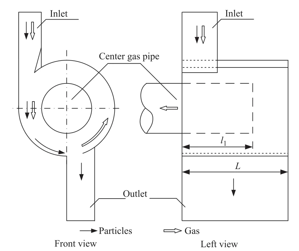
Figure 1 Schematic diagram of separator structure
3 Experimental
As shown in Figure 2, the experimental set-up consists of a pitometer, a feed hopper, a screw feeder, a gassolid separator, a storage tank, a U-shaped manometer,a centrifugal force induced draft fan, a gas outlet pipe,and a gas inlet pipe, all forming suction pipelines. The separator was made of methyl methacrylate with an outer diameter of 250 mm and was equipped with a gas outlet pipe with a diameter of 120 mm.
Room-temperature air and fluid catalytic cracking (FCC)catalysts were used as the raw gas and solid materials in the gas-solid separation experiment. The catalyst particles had a density of 1 500 kg/m3, and their particle size distribution is shown in Table 1. Accurately weighed FCC catalysts were added to the feeding hopper and uniformly introduced to the system through the screw feeder. Under the same inlet super ficial gas flow rate of 14.5 m/s, the solid particles were carried by air into the separator, where the solid and gas phases were rapidly separated under the joint action of centrifugal and inertial forces. The gas left the separator through the central gas outlet pipe and the catalyst particles entering the storage tank. The solids were quickly separated, the gas was discharged from the central gas outlet pipe, and the catalyst entered the storage tank. The inlet gas flow rate of the separator was measured using a pitot tube, the solid particle content in the gas was controlled by the screw feeder, the pressure drop across the separator was measured using the U-shaped manometer, and the separation efficiency (η) was calculated using the following equation:

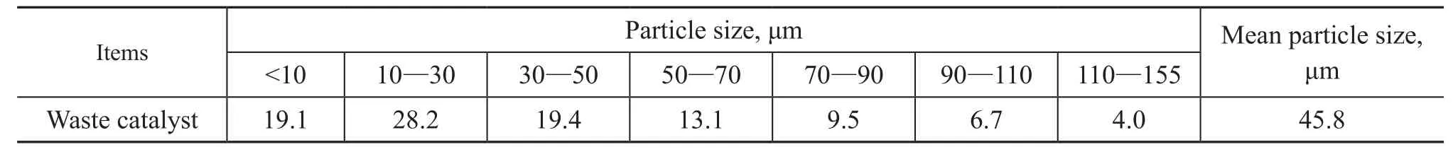
Table 1 Particle size distribution of FCC catalyst
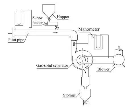
Figure 2 Schematic diagram of experimental set-up
4 Results and Discussion
4.1 Effect of insertion length of gas pipe
By discharging the gas through the central gas outlet pipe in the backward direction (i.e., moving away from the observer in the front view) at various pipe-insertion depths while fixing other structural dimensions of the separator, this study investigated the effect of insertion length of outlet pipe on separator performance. As shown in Figure 3, the insertion length of central gas outlet pipe(l1) was set at 160 mm, 200 mm, or 240 mm, while L was fixed at 300 mm. Experiments were performed to examine the gas-solid separation performance of the three structures.
The gas-solid flow condition inside the separator is the main factor determining the separation performance, and it is also the basis for theoretical analysis. During the experiments of the three different separator structures shown in Figure 3, the air-entrained FCC catalyst particles entered the separator in a tangential direction under the action of the baf fle, and the gas-solid mixture entering the separator swirled about the central gas outlet pipe before the gas phase was finally discharged through the pipe. After moving through a 90° arc, most catalyst particles moved downward into the storage tank under the action of inertial force, while the particles far from the outer wall were entrained by the gas and passed through the space(in a circular motion) under the gas outlet pipe to return to the inlet zone. A small fraction of the air-entrained particles entered the gas outlet pipe, continued to swirl forward, and was finally discharged in the horizontal direction. It is worth noticing that a greater insertion length of central gas outlet pipe can better stabilize and guide the swirling gas flow.
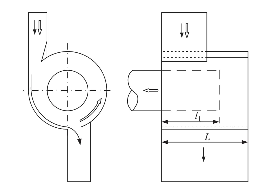
Figure 3 Separator structure with a variable insertion depth of central gas outlet pipe
Figure 4 shows the effect of insertion length of gas outlet pipe on the separation efficiency and pressure drop of the separator. All the three different structures of the separator exhibited a decreasing trend in separation efficiency and pressure drop with an increasing solid particle content in the inlet gas. The decrease in separation efficiency was mainly attributed to the fact showing that as the solid particle content in the inlet gas of the separator increased,those particles with a shorter separation path and smaller particle size would be entrained in a larger quantity by the gas phase, thereby reducing the separation efficiency.Furthermore, the internal friction of the gas was directly proportional to the solid particle content in the inlet gas; thus, the solid particles that were separated and transported to the outer wall generated friction with the wall, which reduced the swirl intensity and the centrifugal force, thereby reducing the pressure drop. Moreover,an increase in the space occupied by the solid particles inside the separator would result in a short path through which the gas moved in the separator, which reduced the separation resistance and in turn decreased the separator pressure drop[13].
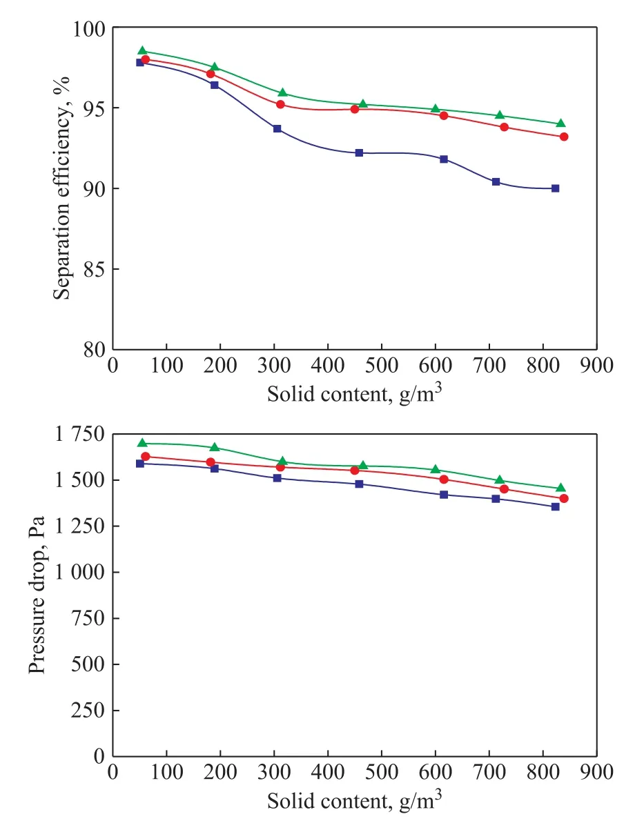
Figure 4 Effect of insertion length of gas outlet pipe on separation efficiency and pressure drop
Figure 4 also reveals that under the same experimental condition, as the insertion length of the central gas outlet pipe of separator increased, the separation efficiency became directly proportional to the separator's pressure drop. Comprehensive analysis of separation efficiency versus separator's pressure drop suggested that it was desirable to use a reasonable insertion depth of central gas outlet pipe to satisfy the requirement for certain separation efficiency, while simultaneously minimizing the separator's pressure drop to save energy. The analysis results showed that the separator structure with l1=200 mm was superior to the other two structures and thereby should be subjected to further optimization as shown in the next section.
4.2 Effect of bypass cylinder
The separator structure in Section 4.1 was further optimized by installing a bypass cylinder behind the central gas outlet pipe (with the same diameter) without modifying the other structural dimensions of the separator. The bypass cylinder was intended to stabilize and guide the gas flow swirling about the central gas outlet pipe, to avoid the turbulent flow and improve the separation efficiency. To experimentally investigate the effect of bypass cylinder on the separator's performance, l1was fixed at 200 mm, while the bypass cylinder length l2was separately set at 30 mm, 50 mm, and 70 mm, respectively (Figure 5).
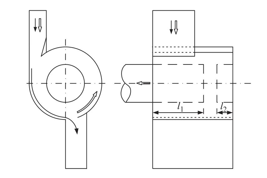
Figure 5 Separator structure with a variable length of bypass cylinder
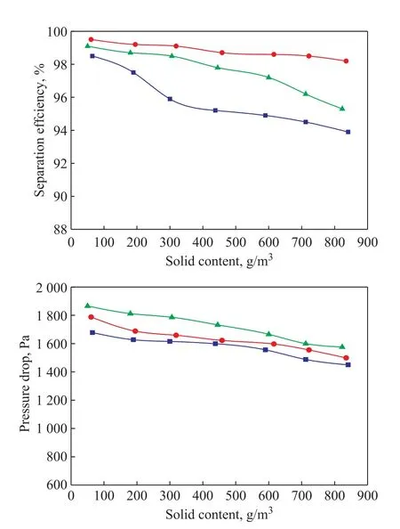
Figure 6 Effect of bypass cylinder length on separation
Figure 6 presents the experimental result of the effect of bypass cylinder on the separation efficiency and pressure drop under the same operating condition. It can be observed that after the introduction of the bypass cylinder in the separator structure, the separation efficiency declined slightly and the separator pressure drop became smaller with an increase in solid particle content in the inlet gas, with both decreasing trends resembling those before the introduction of the bypass cylinder.Furthermore, with an increase in l2, the separator's separation efficiency at first increased and subsequently decreased while its pressure drop gradually increased.Among the three separator structures compared in this study, the highest separation efficiency was achieved at l2= 50 mm, which means that the separation efficiency was affected if the length of the bypass cylinder was either too large or too small. The higher (or lower) the length,the lower the separation efficiency. It was observed in the experiments that the bypass cylinder could stabilize and guide the gas flow swirling about the central gas outlet pipe, denoting that a longer bypass cylinder had a better stabilizing and guiding effect on the swirling gas flow;however, it reduced the distance between the bypass cylinder and the central gas outlet pipe. This fact could lead to an increase in the gas flow rate and turbulence intensity, and in turn, an increase in the entrainment of solid particles by the gas, thereby causing higher friction loss and larger separator pressure drop. On the other hand, a smaller bypass cylinder failed to stabilize and guide the swirling gas flow. Therefore, it was necessary to consider the separation efficiency and the pressure drop to select an appropriate length for the bypass cylinder.Experimental comparison between three structures with a variable l2(Figure 5) indicated that the separator structure with a l2of 50 mm was optimal, and such structure was further optimized as shown in the following section.
4.3 Effect of gas discharge direction
The other dimensions of the gas-solid separator were kept unchanged while changing the direction of central gas outlet pipe to discharge the gas in the forward direction(i.e., moving towards the observer in the front view)via installing a bypass cylinder in front of the central gas outlet pipe with the same diameter. The effect of bypass cylinder length on the separator performance under different gas discharge direction was investigated by experimentally comparing three separator structures(Figure 7) of fixed l1(50 mm) and variable l2(160 mm,200 mm, and 240 mm) under the same operating condition.
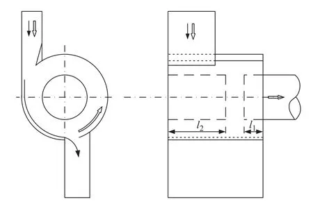
Figure 7 Separator structure with a different gas discharge direction
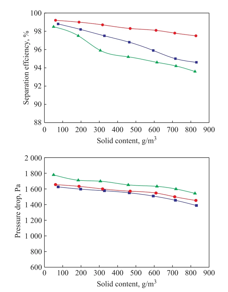
Figure 8 Effect of bypass cylinder length l2 on separation efficiency and separator pressure drop under different gasdischarge direction at fixed l1 of 50 mm
Figure 8 presents the experimental results of separator performance after the direction of central gas outlet pipe was changed (to the forward direction). With an increase in solid particle content in the inlet gas, the separation efficiency and pressure drop of the separator decreased, with both decreasing trends resembling those achieved before the direction of central gas outlet pipe was changed. Under the same experimental condition, the separation efficiency slightly decreased, and the pressure drop became smaller after the aforementioned directional change. It was observed in the experiment that after the direction change, the gas flow swirling about the central gas outlet pipe could directly leave the system in the forward direction instead of the opposite (by reversing its movement/direction twice). This shortened the movement path and weakened the local turbulence, thereby decreasing the separator's pressure drop to a significant degree.
Furthermore, the effect of the front bypass cylinder's length on separator performance was experimentally investigated. The experiment showed that with an increase in the bypass cylinder's length, the separator's separation efficiency at first increased and subsequently decreased while the separator's pressure drop gradually increased.Among the three separator structures, l2of 200 mm led to the highest separation efficiency; however, the efficiency was affected if the bypass cylinder's length was either too large or too small; the higher (or lower) the length, the lower the efficiency. This fact was attributed to the following factors: (1) On the one hand, although the bypass cylinder was intended to stabilize and guide the swirling gas flow, a decrease in the bypass cylinder's length decreased the stability of swirling gas flow and in turn increased the possibility that the solid particles would be entrained by the gas flow and directly enter the gas outlet pipe through “short-circuit” paths without being efficiently separated, thereby decreasing the separation efficiency; (2) On the other hand, the longer the cylinder's length, the stronger its ability to stabilize and guide the swirling gas flow. However, smaller distances between the bypass cylinder and the central gas outlet pipe could lead to a higher gas flow rate, a stronger turbulence intensity,and more severe entrainment of solid particles by the gas. This would decrease the separation efficiency and increase the friction loss. Therefore, the optimal length l2(of the three separator structures allowing for forward discharge of gas), as shown in Figure 7, was 200 mm, and such structure was further optimized as presented in the following section.
4.4 Effect of secondary separation
The experimental results of Sections 4.1, 4.2, and 4.3 showed that among all the investigated separator structures, the structure that allowed for backward gas discharge through a central gas outlet pipe installed in front of a bypass cylinder (Figure 5) and the structure that allowed for forward gas discharge through a central gas outlet pipe installed after a bypass cylinder (Figure 7)were the optimal structures, both reaching a separation efficiency of more than 95% along with a pressure drop of approximately 1 600 Pa. During the experiments, most solid particles were separated by the separator; however,separation was relatively difficult for treating a small amount of fine solid particles, because they were small in both size and mass; thus, the centrifugal force generated under the same gas flow rate was also relatively small,thereby making them more likely to be entrained by the gas flow. The unseparated fine catalyst particles still swirled forward after entering the central gas outlet pipe.Considering the swirling flow characteristics of the fine solid particles, a secondary separation structure was added at the exit of the central gas outlet pipe for secondary separation of fine solid particles, to further improve the overall separation performance of the separator.
The effect of the insertion length l3of secondary separation structure on the overall separator performance was investigated, while fixing l1at 50 mm, l2at 200 mm,and variable l3at 20 mm, 40 mm, and 60 mm, respectively,in the case of forward gas discharge (Figure 9),or fixing l1at 200 mm, l2at 50 mm, and variable l3at 20 mm, 40 mm, and 60 mm, respectively, in the case of backward gas discharge (Figure 10).
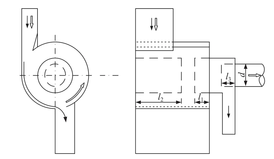
Figure 9 Schematic diagram of the separator structure allowing secondary separation (with the central gas outletpipe discharging the gas in the forward direction;l1 = 50 mm and l2 = 200 mm)
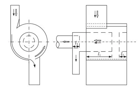
Figure 10 Schematic diagram of the separator structure allowing secondary separation (with the central gas outlet pipe discharging the gas in the backward direction;l1 = 200 mm and l2 = 50 mm)
The experiments showed that the addition of a secondary separation structure could still allow for the optimal primary separation. Along the axial direction, the swirling gas flow entered the secondary separation structure where they moved spirally along the outer wall towards the exit of the central gas outlet pipe. Due to the centrifugal force generated during the swirling, most of the fine catalyst particles were thrown to the outer wall and fell by inertia along the wall surface near the ash discharge outlet to enter the ash discharge pipe. A small fraction of particles was bounced back by the outer wall and entrained by the swirling gas flow, eventually leaving the separator through the secondary gas outlet pipe. The secondary separation structure took advantage of the movement pattern and energy of swirling gas flow discharged from the primary separation structure and could thereby further improve the overall separation performance of the separator.
As shown in Figure 11, for the separator that allowed for secondary separation with forward gas discharge,a maximum overall separation efficiency of more than 99.5% (with a pressure drop of approximately 1 795 Pa)was achieved when the insertion depth l3of secondary outlet pipe in the primary outlet pipe (i.e., central gas outlet pipe) was 40 mm; for the separator that allowed for secondary separation with backward gas discharge,a maximum overall separation efficiency of more than 99.6% (with a pressure drop of approximately 1 846 Pa)was achieved when the insertion depth l3was 40 mm.It can be observed that smaller or larger insertion lengths of secondary outlet pipe would be not conducive to the improvement of separation efficiency. This fact is attributed to several factors: (1) On the one hand, a larger insertion length of the secondary outlet pipe shortens the distance between the entrances of secondary and primary outlet pipes, which in turn reduces the available space of gas in the separator and shortens the movement path,thereby increasing the probability that solid particles could be entrained by the gas to directly enter the outlet pipe without separation. (2) On the other hand, a smaller insertion length destructs the normal swirl core and makes the swirl flow unstable, which, in turn, is likely to cause “short-circuit” paths for the gas in the secondary separation stage and thereby a decrease in the separation efficiency.Moreover, Figures 11 and 12 show that compared with the backward gas discharge, the separator structure allowing for the forward gas discharge through the central gas outlet pipe had a slightly lower overall separation efficiency, while the overall pressure drop was lower to a significant degree due to a decrease in gas flow resistance.
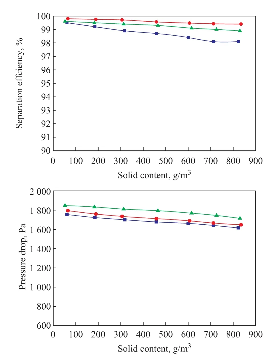
Figure 11 Effect of the addition of secondary separation structure on the overall separation efficiency and pressure drop (with the forward gas discharged through the central gas outlet pipe, l1 = 50 mm, l2 = 200 mm)
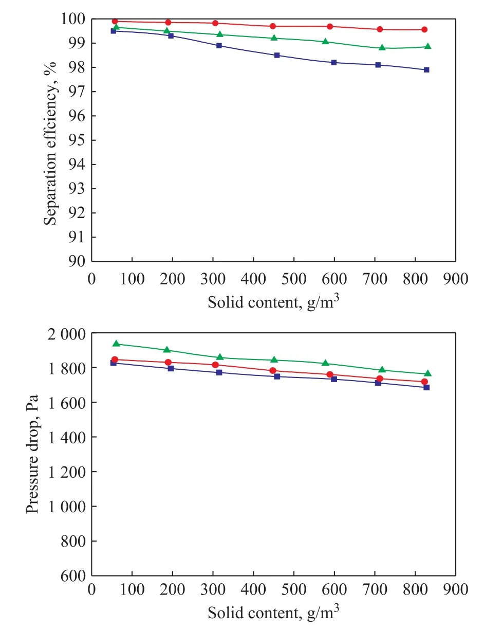
Figure 12 Effect of the addition of secondary separation structure on the overall separation efficiency and pressure drop (with the backward gas discharged through the centralgas outlet pipe, l1 = 200 mm, l2 = 50 mm)
Therefore, changing the direction of central gas outlet pipe of a gas-solid separator can balance, to a certain degree, the requirements for two evaluation indices of the separator, viz.: the separation efficiency and the pressure drop, which are essential for improving the overall separation performance of the separator.
5 Conclusions
(1) The insertion length of central gas outlet pipe in a gassolid separator has a great impact on the performance of the separator, with increase in the insertion length being favorable for stabilizing and guiding the swirling gas flow. As the insertion length of central gas outlet pipe increases, the separation efficiency increases to a certain degree while the pressure drop becomes greater.The insertion length of the central gas outlet pipe should be sufficient for meeting the requirement for certain separation efficiency while minimizing the separator's pressure drop to save energy.
(2) The bypass cylinder in a gas-solid separator can enhance the stability of swirling gas flow, and guide the gas flow to a significant degree, allowing the gas flow to swirl stably between the separator housing and the central gas outlet pipe while reducing turbulence, which in turn can facilitate the separation of solid particles under the action of centrifugal and inertial forces. A proper length of bypass cylinder can help strike a balance between highseparation-efficiency and low-pressure-drop requirements.
(3) A change in the direction of central gas outlet pipe in a gas-solid separator will change the movement path of gas flow and result in local turbulence; however, it has little influence on the separation efficiency. In the case of backward gas discharge through the central gas outlet pipe, the swirling gas flow is required to reverse its movement direction twice before backward discharge,which can result in strong local turbulence and large pressure drop. In the case of forward gas discharge, the gas flow can directly be discharged from the system in the forward direction without a need to undergo directional reversion twice as required for backward discharge,thereby shortening the movement path of gas flow,reducing local turbulence, and decreasing the separator pressure drop to a certain degree.
(4) The secondary separation structure in the separator takes full advantage of the movement pattern and energy of swirling gas flow discharged from the primary separation structure to further improve the overall separation efficiency of the separator, particularly for fine solid particles. Under the given experimental conditions,the separator separation efficiency is greater than 99.5%,and the pressure drop does not exceed 1 846 Pa.
Acknowledgments: The authors gratefully acknowledge the financial support from the National Natural Science Foundation of China (21576294 and 21706287).
- 中國煉油與石油化工的其它文章
- Effect of Nano-coppers with Different Dimensions on Tribological Properties of Lithium Grease
- Complete Nitrogen Removal through Integrating Anammox and Autotrophic Denitrification in an UASB Reactor
- Pressure Swing Distillation for Separation of Ethyl Acetate and Ethanol in Sub-plateau Region
- A Lumped Kinetic Model for Low- and Medium-Temperature Coal Tar Hydrocracking Process
- Effect of Morphological Structure of PtSnNa/ZSM-5 on Its Catalytic Performance in Propane Dehydrogenation
- Effect of Ball-Milling Time on the Performance of Ni-Al2O3 Catalyst for 1,4-Butynediol Hydrogenation to Produce 1,4-Butenediol