Robustifying Dynamic Positioning of Crane Vessels for Heavy Lifting Operation
Jun Ye, Spandan Roy, Milinko Godjevac, Vasso Reppa, Member, IEEE, and Simone Baldi, Senior Member, IEEE
Abstract—Construction crane vessels make use of dynamic positioning (DP) systems during the installation and removal of offshore structures to maintain the vessel’s position. Studies have reported cases of instability of DP systems during offshore operation caused by uncertainties, such as mooring forces. DP“robustification” for heavy lift operations, i.e., handling such uncertainties systematically and with stability guarantees, is a long-standing challenge in DP design. A new DP method,composed by an observer and a controller, is proposed to address this challenge, with stability guarantees in the presence of uncertainties. We test the proposed method on an integrated cranevessel simulation environment, where the integration of several subsystems (winch dynamics, crane forces, thruster dynamics, fuel injection system etc.) allow a realistic validation under a wide set of uncertainties.
I. INTRODUCTION
WITH the shortage of onshore energy sources, the need for energy is more and more satisfied by offshore wind turbines and offshore oil fields. These structures are transported/installed offshore by construction crane vessels.During offshore heavy lifting operations, the vessel needs to maintain its desired position via the so-called dynamic positioning (DP) system [1]. For a DP system to be effective,it is required to counteract the effect of external environmental forces such as wind and waves [2]–[5]. While attempting the positioning task, a DP system is subjected to a wide variety of uncertainty [6], such as the crane load [7]. For construction vessels such as dredgers, heavy-lift vessels, and pipe-laying vessels, additional uncertainties arise: in particular, uncertainties from unmodelled dynamics of the propulsion system and unmodelled forces become crucial during offshore heavy lift operation (see Fig.1). Unmodelled dynamics of the propulsion system affect the precision of the DP system, since the propulsion system of a vessel cannot provide a fast response against disturbances induced by waves or measurement noises [3]; also, studies have shown that unmodelled forces propagating through the crane wires during heavy lifting operation (such uncertainties are commonly referred to as mooring forces) can cause unstable oscillatory behavior of the DP system [8], [9]. These uncertain scenarios bring challenges in the design of DP systems, which are of high interest due to the hazard during offshore heavy lifting operation.
In view of these challenges, research has focused on designing DP systems for offshore cranes in the presence of uncertainties [10]–[18]. Some works [10]–[12] mostly concentrated on the uncertainties in crane and load, neglecting uncertainties in vessel dynamics. Other works [13]–[18]studied structural uncertainties (e.g., mooring, damping forces) during offshore construction, neglecting the effect of disturbances and slow propulsion dynamics on DP performance. To address all uncertainty aspects in a comprehensive way, one should augment the DP system with an observer, whose task is to filter out disturbances in position/velocity measurements [1], [3], [19]. The design of such observers requires the accurate structural knowledge of the vessel dynamics and it is thus sensitive to unmodelled dynamics, as shown in [20]. It is worth remarking that literature provides observer designs such as high gain observer[21], extended state observer [22], and so on. However, the fast estimation response which is typically sought via these observers may not be suitable for real DP operation, mainly due to the fact that the thrusters and propellers of heavy-lift vessels cannot handle fast control command owing to their sheer sizes and their non-ideal behavior. There is no guarantee in general that the signals filtered by the observer will make the DP system operate in a stable way under such practical non-ideal effects [23]. Furthermore, recent studies on the control of offshore cranes focus on the vertical plane of the crane-load system, and neglected the impact from the sway disturbances and thruster delay [24]. The augmentation of a DP system with an observer results in a composite design. To the best of the authors’ knowledge, composite DP designs without requiring accurate structural knowledge of vessel dynamics and with stability guarantees in the presence of uncertainty and unmodelled propulsion dynamics are missing in the literature.

Fig.1. Overall process plant model for the construction crane vessel. Unmodelled dynamics of the propulsion system affect the DP precision. Also, during offshore heavy lifting operation, instability of DP systems has been reported due to large mooring forces, which is the horizontal component of τ crane.
To address this long-standing challenge, we treat mooring and hydrodynamics terms as the summation of a nominal part(which is known) and a perturbed part (which is unknown but bounded). The bounds of uncertainties do not require structural knowledge of the unknown dynamic terms, and can be used for robust control (worst-case) design. Meanwhile, the effect of the observer error (filtering) is proven to be bounded via robust stability analysis. The effectiveness of the proposed composite design is verified under the influence of various uncertainties via a realistic six DoFs simulation model, based on the S-175 model from MSS toolbox [25] with vessel dynamics generated by WAMIT, and augmented with a DP system and a hydraulic crane. Preliminary work by the authors on robust DP for heavy lift vessels was done in [26]: however,in [26] the presence of unmodelled propulsion dynamics is neglected. A point of interest of this study is to show that neglecting propulsion dynamics (engine dynamics, thruster dynamics, etc.) is not acceptable as it can lead to unstable DP behavior.
Summarizing, the innovations of this work are:
a) A detailed physical modelling for heavy lifting operations, where the integration of several subsystems allows to realistically simulate the effect of uncertainties;
b) A composite observer and controller solution to DP for offshore heavy lifting operations which, without requiring accurate structural knowledge of the vessel, can be proven stable even in the worst-case uncertainty settings (robust design). The proposed composite design comprises an artificial delay based method to tackle the unmodelled propulsion dynamics without priori knowledge.
c) Key performance indicators (KPIs) to guide the design while considering worst-case uncertainty and worst-case performance.
The paper is organized as follows: Section II models the physics of heavy lifting; Section III proposes the control strategy while Section IV analyzes its stability; simulation results are in Section V, with conclusions in Section VI.
The following notations will be used: λmin(?) and ||?||represent minimum eigenvalue and Euclidean norm of (?)respectively; I denotes identity matrix with appropriate dimension; the trigonometric functions sin(?), cos(?), and tan(?) are abbreviated as s?, c?, and t?; a vector x ∈L∞implies that x is bounded in the infinity norm (cf. [27, Ch. 3]).
II. CONTROL OBJECTIVE
Because it was reported that instability in DP systems occurs during heavy-lift operation due to large mooring forces, it is crucial to model realistic dynamics. A realistic model that can describe realistic dynamics along six DoFs is commonly referred to in literature as a process plant model[28]: the process plant model in this work is based on the S-175 model from MSS toolbox [25], with vessel dynamics generated from WAMIT [29] and integrated with DP system and hydraulic crane. A schematic of the overall model is shown in Fig.1. The process plant model allows to test a wide range of uncertain dynamical scenario, by including vessel dynamics, environmental loads, hydraulic crane, position controller, thrust allocator, diesel engines and thrusters. The various modules of the simulation model are individually detailed hereafter, and the simulation variables and parameters are collected in Table I.

TABLE I SYSTEM PARAMETERS AND VARIABLES
A. Vessel Dynamics
Two coordinate systems are used to describe motion: bodyfixed coordinate system and north-east-down (NED)coordinate system. For the body-fixed coordinate system, the center of origin is fixed on the vessel, with x-axis positive to the front of the vessel, y-axis positive to the right of the vessel, and z-axis positive downwards. For the NED coordinate system, the origin is fixed on the earth surface,with x-axis pointing the north, y-axis pointing to the east, and z-axis pointing downwards. The resulting dynamics of motion describe the six DoFs of the vessel: we follow the approach in[29, Eq. 8.5] under the assumptions of low velocity and acceleration and of irrotational and constant ocean currents:


where ηf=[x y z ? θ ψ]Tis the vessel position in NED coordinate system, in which (x,y,ψ) denote the surge, sway and yaw angle of the vessel, and (z,?,θ) denote the heave position, roll and pitch angles of the vessel; νfr=νf?νcdenote the relative velocity of the vessel with respect to the current velocity νc=[uc,vc,0,0,0,0]T, where νf=[u,v,w,p,q,r]Tis the vessel velocity (all in body-fixed coordinate system); J′(?,θ,ψ) is the body-to-NED rotation matrix

where
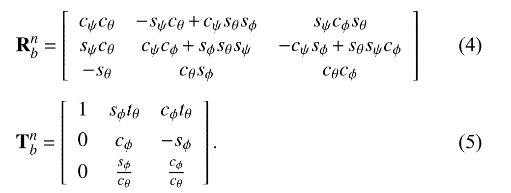
The terms MRB,MA,C(νfr), and Dsdenote the rigid body mass matrix, added mass matrix, Coriolis terms, and hydrodynamic damping terms, respectively; consistently with[29], the inertia matrix MRB∈R6×6is defined as


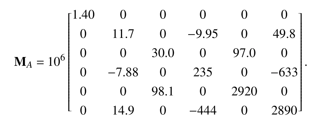
For a vessel which is symmetric on port-starboard, the added mass and added inertia matrix can be expressed as


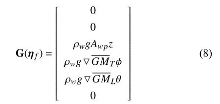
When the roll and pitch angle is small, the restoring force G(ηf) can be expressed as

B. Environmental Loads
The environmental loads can be seen as the combination of wind load and wave load. Wind load is related to the surface of the vessel above the waterline, wind velocity and attack angle of the wind, causing additional air pressure to the surface of the vessel. For a vessel in DP control mode with zero speed over ground, the wind load can be defined as

where ρais air density, Vwis wind speed, modeled as a combination of slow-varying wind and wind gust; CX, CY, CZ,CK, CM, and CNare nondimensional coefficients related to the angle of attack, and can be caculated from [29, Eq.8.30–8.36]; AFwand ALware the frontal and lateral project areas above the waterline, while HFwand HLware the centroids of the two areas, and γwis the angle of attack of the wind. The wind angle is considered to be slowly varying around the mean wind angle. The wave load τwaveis modeled as a the sum of a first-order wave (zero mean oscillation load)and a second order wave (mean wave drift load without oscillatory component) (cf. [29, Eq. 8.88–8.89] for their detailed structure).
C. Hydraulic Crane
The crane model consists of a hydraulic crane and the crane wires. Assuming no slack, the crane wires are modelled as a spring and a damper [30]


The crane winch is actuated by a PI-controlled hydraulic motor, typically designed by the crane manufacturer. The output torque T of the hydraulic motor is [31]

where Q is the inlet flow rate per revolution; ?p is the pressure difference between the inlet flow and the outlet flow,ηhydis the efficiency of the motor; r is the radius of the drum that the cable is wound on, where δT is the difference between the user-defined required torque and the actual torque. The PI controller has been tuned according to reaction curve based methods as in [32, Sect. 6.5] in such a way that the time constant of the output torque is around 1 s.
D. Propulsion System
To properly capture the dynamics of the propulsion system,we use a mean-value first principle modelling for enginepropeller interaction (cf. [33], [34] for details). The diesel engine is modeled as a four-stroke engine with six cylinders

where Mbis the output torque; ηeis the efficiency, mfis the fuel injection in gramme; kLHVis the lower heating value(a.k.a fuel energy/mass ratio), and nengis the engine speed in rotation per second. The thrust force for each thruster i is

where ρwis the water density; npis the rate of revolution;Dpropis the diameter of the propeller; Ktaand Ktbare two constant parameters; VAis the arriving water velocity.
Similarly, the propeller torque is

A shaft is connected between the diesel engine and the propeller with a gearbox. The rate of revolution of the propeller can be described as

where igbis the gearbox ratio, ηtrmis the transmission efficiency, and Itotis the total mass of inertia of the propulsion system. The overall thrust force on the vessel is computed as

where the summation is to be intended as vector summation.A thrust allocator is designed for the engine-thrust system

where Btais designed based on the knowledge of the positions of the thrusters [30].
III. CONTROLLER DESIGN
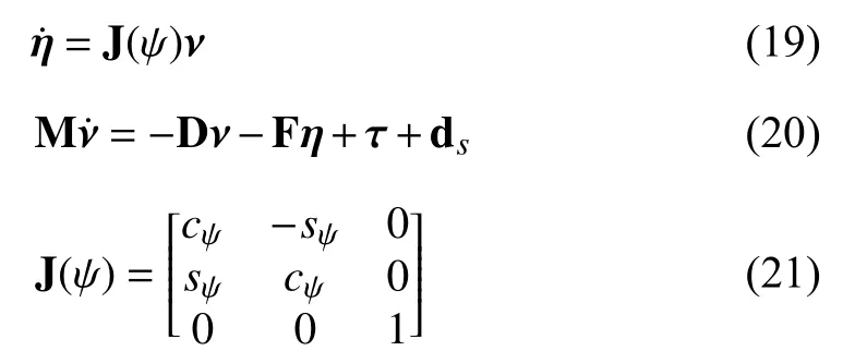
While the performance of a DP system is better validated on realistic six DoFs as in the process plant model (1) and (2), the DP design is conventionally performed on a three DoFs control plant model [28]. The three DoFs arise from the[x,y,ψ] coordinates (also known as surge, sway, and yaw) [29,Sect. 7.3.1], resulting in

Remark 1 (Control Plant Model vs. Process Plant Model):
Reducing a process plant model to a control plant model, i.e.,from 6 to 3 DoFs, introduces unmodelled dynamics.Unmodelled dynamics in (20) as compared to (2) are
1) The terms C ,G , and g0;
2) The thruster dynamics;
3) The damping components of the crane wires.
Therefore, the simulations using the six DoF process plant will allow to test the performance of the proposed design in representative dynamical uncertain scenarios. A DP system must be designed so as to tackle all such uncertainties.
In the following we will describe how uncertainty is included in the three DoF control plant model (20).
A. Uncertainty Setting
Henceforth, for compactness, J(ψ) will be represented as J,and the system dynamics (19) and (20) is represented as

A1?M?1F,A2?M?1Dd ?M?1dsM
where , and is positive definite matrix [20]. Note that in crane vessels the exact values of the positive definite matrices A1and A2is subject to uncertainty. The following assumption highlights the nature of uncertainties considered in this work for dynamics (20):

Remark 2 (Robustification Philosophy): The perturbation ranges ?Aidefine the worst-case uncertainty in mooring and hydrodynamic damping forces. The upper bound ?d defines the worst-case environmental conditions. The knowledge of these terms is required if one aims at proving stability of the DP system in the worst-case uncertainty settings. Differently from mooring and hydrodynamic damping terms, the mass M of a vessel is typically known with little uncertainty. In fact,uncertainty in mass matrix arise from movements in water with high acceleration or deceleration (added mass terms),which are negligible during DP operation [29]. Such values of the vessel can be obtained from the data provided by contractors.
B. Observer-Based Robust Control
The composite DP design can now be proposed

whose stability analysis will be given in Section IV. It consists of a composite design of robust controller and observer:observers for positions and velocities via (24) and (25) helps to filter out disturbances and ease the thrusters’ action (cf.(18)).
In order to handle the worst-case uncertainty settings, the observer and control gains H,K,K1,K2,ρ1, and ρ should be properly designed. The design of such gains is proposed as
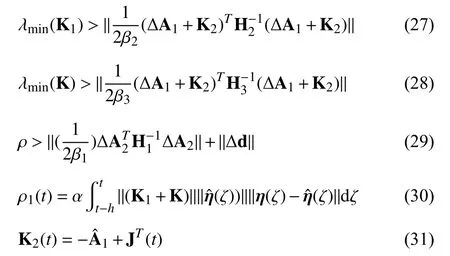
where α>1; βiand Hii=1,2,3 denote positive scalars and positive definite matrices that must satisfy

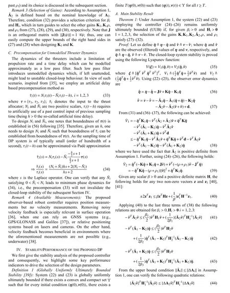

Remark 5 (Innovative Aspect of the Proposed Design): The notable feature of the stability result for the proposed DP scheme (24)–(26) is its composite nature: the design jointly provides robustness against model uncertainties, unmodelled thruster dynamics and filtering against measurements. In stateof-the-art DP systems, no composite stability was proposed:either robustness is achieved neglecting filtering (cf. [1], [3],[19]), or filtering is implemented neglecting model uncertainties (cf. [13]–[18]) or neglecting thruster dynamics such as engine dynamics, delay [26].
Remark 6 (Design Guidelines): It can be noticed from (53)and (55) that high values of K,K1,ρ, and α (determined from(27)–(30)) help to reduce ι and improve control performance.On the other hand, the upper bound (56) reveals that higher values of the above mentioned gains demands higher control effort. Thus, a designer has to make a trade-off between the positioning performance and control effort.
V. SIMULATION RESULTS AND ANALYSIS
In this section, the performance of the proposed controller is validated under the two following scenarios for a heavy lift vessel in “moored” stage (i.e., the heavy load is attached to the platform, and the load is fully/partly on the platform, while the vessel is taking out loading/unloading work trying to transfer the load to/from the vessel from/to the platform):
S1 in the first scenario, the thrusters are considered to be ideal, i.e., no constraint is imposed on its ability of responding to variations in the control input; and
S2 in the second scenario, non-ideal thrusters are considered where low pass filters are used to limit the response to variations in the control input, in line with Section III-C.
Various dynamics parameters of the S-175 ship model used in this work are available as open source in [25]: for convenience, we have summarized them in Appendix.Simulations for both the scenarios are carried out under the“smooth-to-slight” sea-state (i.e., sea state 2) with a current of 0.6 m/s (i.e., 0.3 m/s in north and approximately 0.5 m/s in east). The reason we have chosen sea state 2 is that for most companies, this is the maximum sea state allowed to carry out offshore heavy lift operations [23]. The environmental data under such sea-state are shown in Table II and Fig.2.

TABLE II ENVIRONMENT SETTING
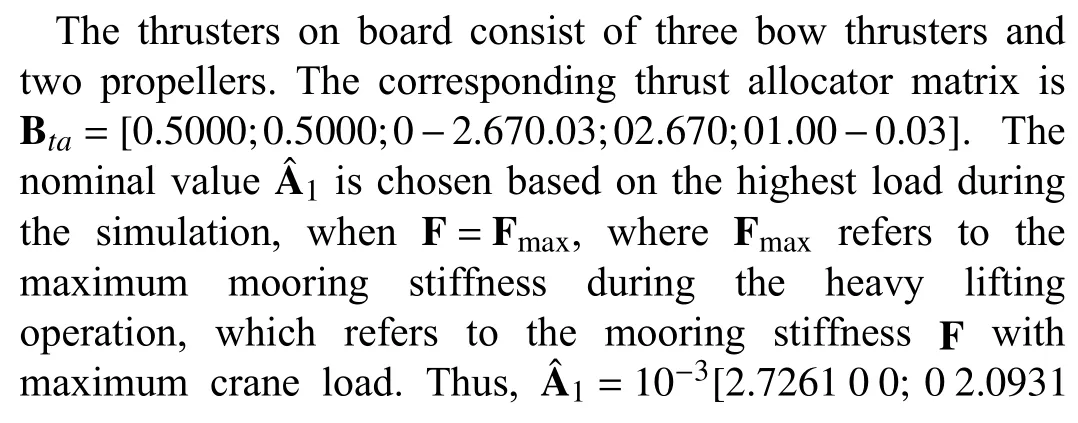
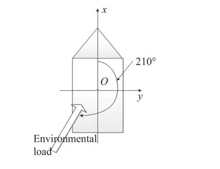
Fig.2. Environmental load on the vessel.


Fig.3. Tension in the crane wires.
A. Results From Scenario S1
The performance of the proposed controller in this scenario is shown in Figs. 4–6. Its performance is compared with the design in [30], which employs a nonlinear passive observer with a (non-robust) PID controller. The PID controller is tuned for a load of 2460 ton (i.e., approximately 10% mass of the vessel) on the platform under sea state 2, and the parameters are fixed during the whole simulation. The performance of both the proposed and the PID strategy can be checked in the first column of Tables III and IV (? =0). Both the root mean square error (RMSE) and the maximum offset from the desired equilibrium position are reported. These values show that the proposed approach reduces the RMSE by 89% in north direction, 50% in east direction and 82% in yaw.Offset reductions are 95% in north direction, 78% in east direction, and 83% in yaw.
B. Results From Scenario S2
In this scenario, the thrust allocators are considered to be embedded with the following low pass filters:
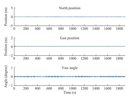
Fig.4. Vessel position in scenario S1 employing the proposed controller.

Fig.5. Crane forces and moment in scenario S1 with the proposed controller.

TABLE III PERFORMANCE OF THE PROPOSED CONTROLLER WITH THRUSTER DYNAMICS

where ? denotes the filter time constant.
The performance of the proposed controller and same PID controller in scenario S1 is verified for five different ?s as ?=1,2,3,4 , and 5. These values correspond to five possible unmodelled thruster dynamics. The performance of both controllers are tabulated in Tables III and IV, respectively (cf.the columns corresponding to ?=1,2,3,4 , and 5).Furthermore, for the value ?=3, the results are shown in Figs. 7–9 (proposed controller), and Figs. 10 and 11 (PID controller). The tabulated data reveal that both the proposed controller and the PID controller loose performance as ? increases. However, the proposed controller outperforms the PID controller for all ?. From the values in the columns ?=3 it is possible to see that the proposed approach reduces the RMSE by 98% in north direction, 53% in east direction and 87% in yaw. Offset reductions are 97% in north direction,85% in east direction and 80% in yaw. These are similar or larger improvements as compared to ? =0: in other words, the performance of the proposed approach is consistent for a large range of uncertainties.

TABLE IV PERFORMANCE OF PID CONTROLLER [30] WITH THRUSTER DYNAMICS
From Figs. 7 and 8 (proposed controller), and Figs. 10 and 11 (PID controller) it is evident that the PID controller produces large oscillations which are at the onset of instability. Such large oscillations result in forces through the crane wires which are around 10 times larger than the proposed approach.
C. The Role of Propulsion Dynamics and Sea State
A simulation under scenario S2 with ?=1 employing the robust observer [26] in Fig.12 reveals that propulsion dynamics plays a huge role in determining stability of the DP system. As a matter of fact, state-of-the-art designs can be
Fig.7. Vessel position in scenario S2 with the proposed controller, ? = 3.unstable due to lack of robustness.
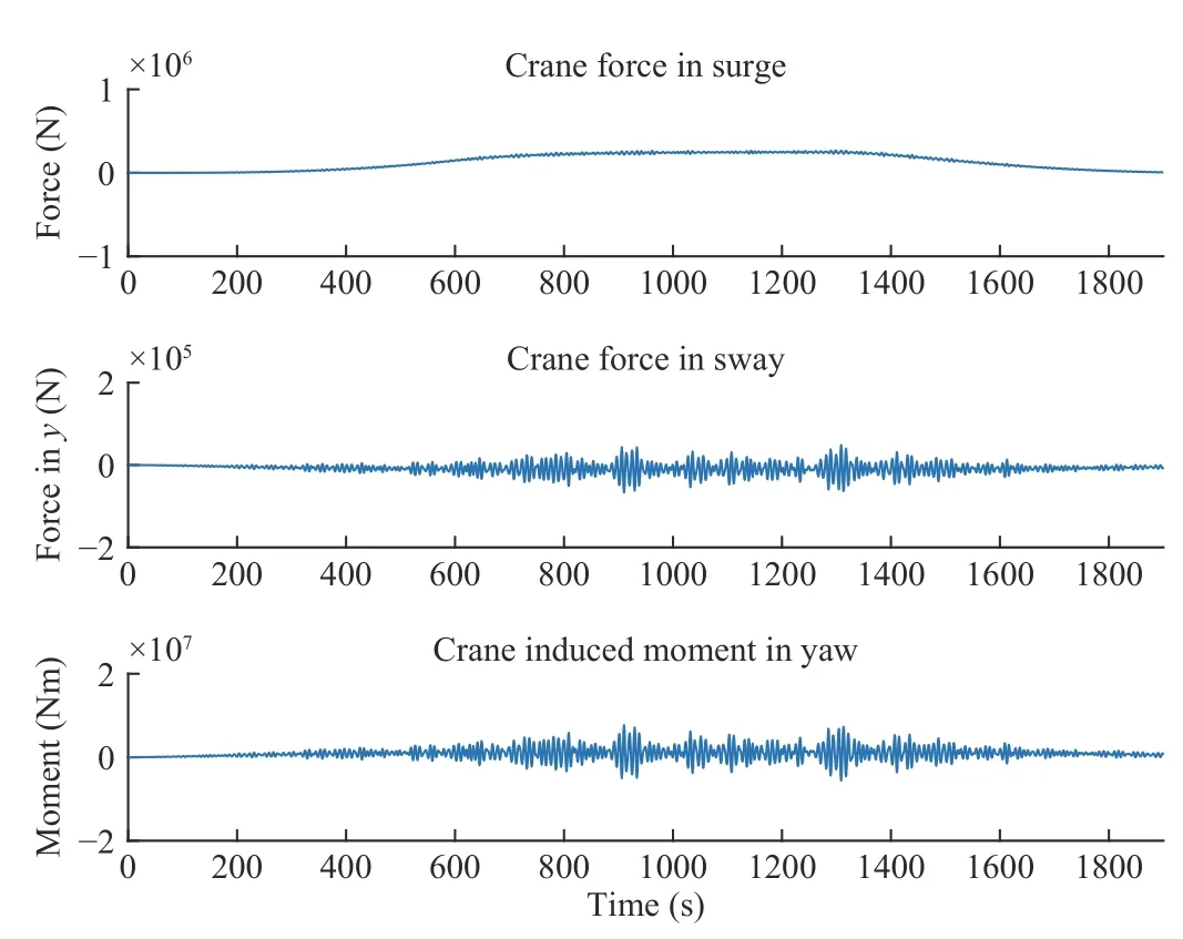
Fig.8. Crane forces and moment in scenario S2 with the proposed c ontroller, ? = 3.

F ig. 9. Thrust forces and moment in S2 with the proposed controller, ? = 3.

Fig.11. Crane forces and moment in scenario S2 with PID controller, ? = 3.
More simulations are made with different sea states (Table V),and different loads (Table VI). These results show that the proposed robust controller can still maintain the position of the vessel with a maximum offset of 0.21 m in north, 0.3 m in east, and 0.3?in yaw under sea state 4 (Table V). Moreover,the proposed controller is quite insensitive to different loads,according to Table VI.
VI. CONCLUSIONS AND FUTURE WORK
An observer-based robust DP system was presented for construction crane vessels. The closed-loop control system was proven to be stable under against uncertainty; the effectiveness of the proposed scheme was verified in comparative simulations incorporating real-life uncertain scenarios such as changing mooring force, environmental load, unmodelled propulsion dynamics, and thruster delay. An important future work is embed estimators in the DP control framework to avoid worst-case uncertainty bounds.

Fig.12. Unstable behavior with controller from [26], ?=3, due to n eglecting propulsion dynamics.

TABLE V SIMULATION RESULTS OF THE PROPOSED ROBUST CONTROLLER UNDER DIFFERENT SEA STATES, ?=3
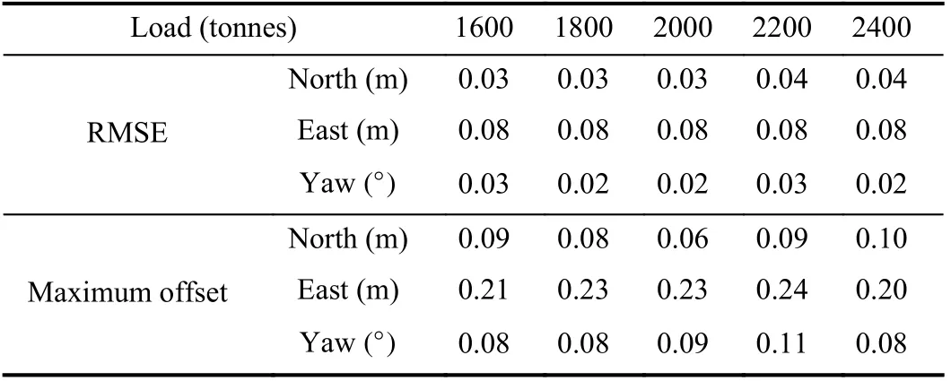
TABLE VI SIMULATION RESULTS OF THE PROPOSED ROBUST CONTROLLER WITH DIFFERENT LOADS, ?=3
APPENDIX
NUMERICAL VALUES FOR THE PROCESS PLANT MODEL
The parameters mentioned in Section II are summarized in Table VII, and they are based on the open source S-175 vessel model [25].
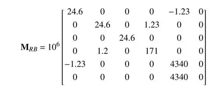

TABLE VII NUMERICAL VALUES FOR THE VARIOUS CRANE VESSEL COMPONENTS
Other system parameters are provided in Table VII, which are used to generate the other system dynamics terms such as C,Ds,G,g0) [29, Section 7.3.1] and propulsion dynamics terms as elaborated in Section II.
 IEEE/CAA Journal of Automatica Sinica2021年4期
- IEEE/CAA Journal of Automatica Sinica的其它文章
- Dynamic Evaluation Strategies for Multiple Aircrafts Formation Using Collision and Matching Probabilities
- Task Scheduling for Multi-Cloud Computing Subject to Security and Reliability Constraints
- Vibration Control of a High-Rise Building Structure: Theory and Experiment
- Residual-driven Fuzzy C-Means Clustering for Image Segmentation
- Decoupling Adaptive Sliding Mode Observer Design for Wind Turbines Subject to Simultaneous Faults in Sensors and Actuators
- Property Preservation of Petri Synthesis Net Based Representation for Embedded Systems
