A study on the surface overpressure distribution and formation of a double curvature liner under a two-point initiation
Jie Liu ,Xi Chen ,Zhong-hua Du
a Nanjing Vocational University of Industry Technology,Nanjing,210023,China
b Nanjing University of Science and Technology,Nanjing,210094,China
Keywords:Unit-shaped charge Double curvature liner Regular oblique reflection Two-point initiation Penetration Numerical simulation
ABSTRACT The formation mechanism of an EFP(explosively formed projectile)using a double curvature liner under the overpressure effect generated by a regular oblique reflection was investigated in this paper.Based on the detonation wave propagation theory,the change of the incident angle of the detonation wave collision at different positions and the distribution area of the overpressure on the surface of the liner were calculated.Three-dimensional numerical simulations of the formation process of the EFP with tail as well as the ability to penetrate 45# steel were performed using LS-DYNA software,and the EFP velocity,the penetration ability,and the forming were assessed via experiments and x-ray photographs.The experimental results coincides with those of the simulations.Results indicate that the collision of the detonation wave was controlled to be a regular oblique reflection acting on the liner by setting the dimensions of the unit charge and maintaining the pressure at the collision point region at more than 2.4 times the CJ detonation when the incident angle approached the critical angle.The distance from the liner midline to the boundary of the area within which the pressure ratio of the regular oblique reflection pressure to the CJ detonation pressure was greater than 2.5,2,and 1.5was approximately 0.66 mm,1.32 mm,and 3.3 mm,respectively.It is noted that pressure gradient caused the liner to turn inside out in the middle to form the head of the EFP and close the two tails of the EFP at approximately 120μs.The penetration depth of the EFP into a 45# steel target exceeded 30 mm,and there was radial expansion between the head and tail of the EFP,increasing the penetration resistance of the EFP.Therefore,the structural size of the unit charge and the liner can be further optimized to reduce resistance to increase the penetration ability of the EFP.
1.Introduction
By exploiting the cumulative effect of a charge,a liner assembled with dynamite can quickly form the penetrator with high initial velocity under the action of the explosion waves.This is a technique that has been widely used and studied for many years.Researchers[1-5]have investigated various methods to control not only the parameters influence of the different structures but also the materials for the explosives or liner to obtain better-shaped projectiles with large aspect ratios.It has been proven that the overpressure produced by detonation wave collisions can improve the utilization rate of the shaped charge and the initial velocity of formed projectiles while further optimizing the tail of an EFP such that the EFP achieves better long-range flight and aerodynamic stability.
At present,the overpressure formed by multi-point initiation and the interactions of the detonation waves with the liner has become a focus of current research[6-8].In the charging structure,multi-point initiation and the use of a waveshaper or double layer charges with different detonation speeds are the most common techniques to achieve normal collision,regular oblique reflection,and Mach reflection in the sequence of multiple detonation waves.Additionally,adjusting the dimensions of the charging structure or the initiation diameter are methods used to control different types of detonation wave collisions [9-12].Some scholars have conducted numerical and experimental studies on the influence of the initiation mode,including the number and positions of detonation points,the symmetry of the initiation point,and synchronicity error,on the formation of EFP on the basis of numerical simulation technology.Bouet et al.[13]simulated an explosively formed projectile with star-shaped fins by setting different detonation points on a cylindrical charge.Subsequently,Li et al.[7]studied the effects of the initiation mode on the velocity and length-diameter ratio of an explosively formed projectile by applying an annular multipoint initiation circuit to a charge.Cardoso et al.[14]studied the effects of five different sets of detonation conditions,involving the number and relative positions of detonators,on the formation of a typical EFP,and they observed that increasing the number of detonators and off-center distance promoted the development of fins and energy release.Furthermore,the effects of the synchronicity error of the three-point initiation on the formation of fins on an explosively formed projectile for a typical charge with a 65 mm diameter were investigated by Liu and Li et al.[8,15].However,detonation wave interactions and EFP formation on a unit charge under twopoint initiation have not been studied so far.Hull’s [16,17]research gives a comparison between the theoretical calculations and experimentally measured pressures of PBX-9501 detonation waves during regular oblique reflection and Mach reflection,which demonstrate that the two pressures coincide better in the regular oblique reflection region and that the intensity of the overpressure after the reflection wave is stable;however,the pressure difference between the theoretical calculation and the experimental measurement in the Mach reflection region is notable and the pressure of the Mach stem decreases rapidly with the increase of the incident angle,which is an occurrence that has also been demonstrated in subsequent studies by Li [18].Pan et al.[19] conducted an experimental study on detonation wave propagation in cylindrical charges with a waveshaper to impact a copper target.The experimental results of Pan’s research show that the edges of the core hole caused by the collision point generated by a regular oblique reflection were smooth,whereas although the core hole caused by the Mach reflection was similar in size,the edges and the inner surface of the core hole had local cracks and fractures,indicating that the pressure in the region of the regular oblique reflection is more stable than the pressure of the Mach stem under a Mach reflection.Therefore,the overpressure generated by the regular oblique reflection caused by detonation waves is more predictable on the surface of a liner.Current research on different types of detonation wave collisions can be referred to in studies on the use of the Mach reflection to generate overpressure acting on a liner.However,analytical models of a liner under the regular oblique reflection have rarely been used to describe the formation process of an EFP.
In this paper,by setting the charge size to retain the collision of the detonation wave within the region of the regular oblique reflection,the effects of overpressure generated by the regular oblique reflection on a double curvature liner are studied.Using LSDYNA software combined with regular oblique reflection theory and experimental results,analysis of the interactions of the detonation waves and the liner is discussed,and the distribution of the overpressure generated by the detonation wave collision on the surface of the double curvature liner is determined.Next,the formation process of an EFP starting from the formation of the head of the penetrator to the closure of the tail is described,and the experimental results of the EFP penetrating a 45# steel target are presented.The results provide a reference for a single unit-shaped charge for a circumferential MEFP(Multiple Explosively Formed Projectile).
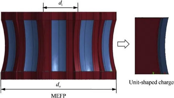
Fig.1. Schematic of the MEFP.
2.Unit-shaped charge and numerical model
2.1.Geometry of the unit-shaped charge
A schematic of a circumferential MEFP are shown in Fig.1 and the ratio of dto dis 0.3.The entire MEFP comprises 12 unit-shaped charges.Adjacent units are separated by 20 mm thick aluminum alloy separators,and spherical prefabricated fragments have been introduced between the separators.According to the studies of Pan[20],when the thickness of the metal material exceeds 16 mm,it can prevent shock initiation by the transmission shock wave of the detonation wave.Therefore,in the case of multi-point synchronous initiation,the separators block interactions of the detonation wave generated by the simultaneous initiation of unit-shaped charges.
The object used in this study is a unit-shaped charge for a circumferential MEFP,the dimensions of which are shown in Fig.2.The geometry of the unit-shaped charge is presented in three views.The charge is observed to be similar to a cuboid structure,and the liner is an arc structure with double curvature,shown in the main and left views.The dimensions of the unit-shaped charge shown in Fig.2 have a charge length,width,and height of L=70,W=26 mm,and H=30 mm,respectively,a liner thickness and width of δ=2.5 mm and w=20 mm,respectively,and a curvature with a radius R=120 mm,R=117.5 mm,and R=15 mm.The charge is surrounded by an aluminum alloy shell with a thickness of 10 mm.The distribution of the two initiation points at the top of the charge indicated by the solid black dots,and two points are detonated simultaneously.This unit charge structure adopted in the subsequent experiments is the same as that in the numerical simulation.
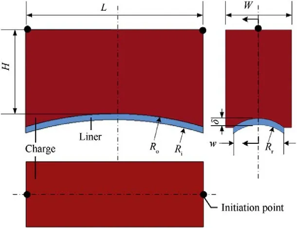
Fig.2. Schematic representation of the unit-shaped charge.
2.2.Finite element model and material properties
The finite element model that included the liner,explosive,shell,target,and air domain was established using LS-PrePost preprocessing software in addition to the simulations performed using LS-DYNA software.The dynamite[8]was RDX-based explosive and uses the material models with high energy and Jones-Wilkins-Lee state equation.The Steinberg-Guinan material model was applied to the oxygen-free copper liner using Grüneisen state equation.The shell was made of T6 aluminum alloy,and the target was 45#steel,both of which adopted the Johnson-Cook material models and Grüneisen state equation to describe the dynamic response of the materials.
The air was modeled with the MAT-NULL material model provided in the LS-DYNA software and Liner polynomial equation of state.To describe the large deformation with Lagrangian grids and the flow material,the Arbitrary Lagrange Euler (ALE) algorithm suitable for fluid-solid coupling analysis was adopted in the numerical calculations.The Euler algorithm was used for the explosive,liner,and air domain,and the ALE multi-material finite element method with common node coupling between the three components was used.The shell and target were described by the Lagrange algorithm and adopted a constant stress solid element.The grid in the numerical models applied hexahedral elements for all parts and the mesh size of the target was 1.0 mm × 1.2 mm × 1.2 mm.The surfaces surrounding the air domain and the target were set as a nonreflecting boundary,and the freedom of movement and rotation of the four-side nodes of the bottom surface of the target board were constrained.The unit system was in terms of cm-g-μs in the calculation model,of which the material parameters are listed in Table 1.
2.3.Verification of the numerical model
The projectile velocities during the initial flight stage measured twice with the copper wire gauze were 1976.28 m/s and 1851.65 m/s,respectively,as shown in Fig.3,and the average speed of the two measurements was 1913.96 m/s.The velocity during the formation process of the liner determined by numerical simulation is presented in Fig.2,where the complete velocity curve of the EFP is divided into two stages by the boundary line at 150 μs.
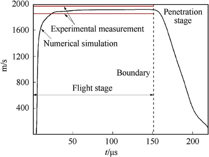
Fig.3. Comparison of the numerical simulation and experimental speed of the EFP.
The first stage indicates the EFP flight in the air domain;the speed rose rapidly from 5 μs,and was then steadily maintained at approximately from 25 to 150 μs,which is within the speed range measured in the two physical measurements and is close to the average of the measured speeds.The second stage indicates the EFP penetrating the target beginning at 150 μs,then continuing to penetrate through the 45# steel target at 200 μs,and finally finishing its path with its speed decreasing linearly and rapidly.

According to Eq.(1),which can be found in Ref.[8],since the vertical distance from the bottom surface of the unit-shaped charge to the upper surface of the target is only 300 mm,the attenuation coefficient α caused by the aerodynamic effects and the flight distance Din the direction of flight is negligible.When the confidence interval of the maximum accepted error λ was set to 10% (λ=0.1)[21],the stable speed of the EFP numerical simulation was within 3% of the measured speed in the two tests.This shows that the numerical simulation is a reasonable approximation of the modeled physical phenomena and can provide a verifiable basis for subsequent analyses.

Table 1 Material parameters used for the numerical simulation [7,14,21,22].
3.Analysis of the detonation wave propagation interactions
3.1.Analysis of the incident angle of the detonation wave propagation
The geometric center at the top of the charge was set as the coordinate origin O,and a three-dimensional Cartesian coordinate system was established as shown in Fig.4.The xoy plane is the symmetry plane of the finite element model.The initiation points were distributed along the x-axis.The coordinates of the two initiation points were (L/2,0,0) and (-L/2,0,0),and the distance between the two points was the length of charge L.The detonation wave propagated independently from the initiation point as an approximate spherical detonation wave.The distance between the center of each element and the initiation point was tDwith the CJ velocity Dand the propagation time t known.The detonation time of each element was calculated according to the distance of the nearest initiation point when there were multiple initiation points.The pressure measurement points on the y-axis were set at the coordinates of (0,h,0),(0,2h,0) and (0,3h,0) where the distance between the measurement points was h=H/3.
The two detonation waves collided at the origin O of the coordinates,and then,the collision point moved in the positive direction along the y-axis and was transformed into a regular oblique reflection.Thus,the equation for the incidence angle φbetween the tangent of the wave front and the y-axis in Fig.4 satisfies the following relationship:

The incident angle in the xoy plane shown in Fig.5 increased gradually with the movement of the collision point from the origin O to the midpoint of the arc of the liner,and the range of the incident angle was 0-40.2.
It can be observed that the propagating wave front first collides on both ends of the liner,and then,the detonation wave propagates along the radius of curvature to the top of the liner.As shown in Fig.6,due to the symmetrical structure of the liner,a local sketch was created where pressure measurement points on the upper surface of the liner in the numerical model are marked for the subsequent distribution of the pressure analysis.
In the calculation,the detonation wave was assumed to be approximately a spherical propagation,and the CJ wave front motion equation can be expressed as follows:

where x=± L/2 is the coordinate value of the initiation point.

Fig.4. Finite element model of the charge and schematic representation of the detonation wave propagation in the xoy plane.
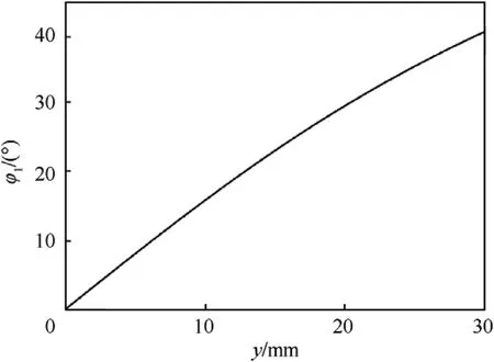
Fig.5. Incident angle of the detonation wave collision along the y-axis.
According to the geometry,the distance from the center of the circle with radius Rand Rto the origin of the coordinate are yand yrespectively.The following equations represent relationships:

where His calculated from the following formula

Based on a double curvature liner,the upper surface equation of the liner can be obtained in the three-dimensional Cartesian coordinate system as:


3.2.Analysis of the interaction of the detonation wave
The type of detonation wave collision was controlled by adjusting the size of the charge structure or the detonation diameter in the charge.The schematic diagram of the regular oblique reflection process of the detonation wave collision in the unit charge is shown in Fig.8.The wave system is composed of the incident wave I,the reflected wave R,and the axis of symmetry.The actual collision point Ois along the axis of symmetry and moves in the positive direction,and the detonation velocity of the CJ wave front is D.
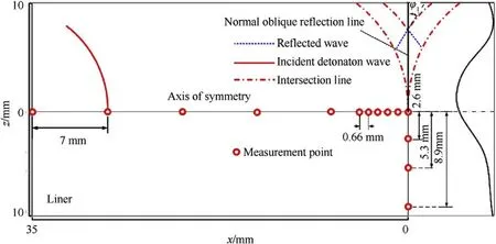
Fig.6. Schematic diagram of the interaction between detonation wave propagation and liner.
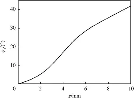
Fig.7. Incidence angle of the wave front at the midline in the top arc of the liner.
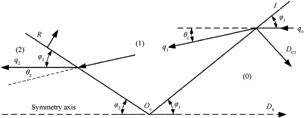
Fig.8. Schematic diagram of the regular oblique reflection of the detonation wave.
The collision point Oof the wave system is fixed and the flow field is divided into three areas [23].The incident angle of the detonation wave is φ.The deflection angle of the incoming flow passing through the incident wave is θ.The reflection angle between the reflected wave and the wall surface is φ.The deflection angle of the incoming flow passing through the reflected wave is θ.According to the geometric relationship,

The incident angle φand the deflection angle θfrom zones(0)to(1) satisfy the following relationship:

where γ is polytropic exponent,which is calculated from the following formula

where ρa(bǔ)nd Pare the initial density of explosives and the CJ pressure,respectively.
According to the wave system of a regular oblique reflection,

According to the Rayleigh-Hugoniot relationship and the wave system,the incident angle φand the deflection angle θsatisfy the following relationship.

where Mis the Mach number of zone (1)

According to Eqs.(9) and (12),both the deflection θand the reflection φangles are functions of the incident angle φ.The curves of θand φabout φare shown in Fig.9 where it can be observed that the reflection angle increases when the incident angle approaches the critical angle,which increases by more than 40,whereas the deflection angle increases slowly,primarily in the range of 8and below.
According to Eq.(8),the critical angle φof the regular oblique reflection and the Mach reflection is 44.59,which was comparable with the range of the incident angle in Figs.4 and 6.The collision process of the detonation wave in the unit charge was maintained in the regular oblique reflection region.The expression of the ratio of the pressure in regions (1) and (2) satisfy the following relationship:

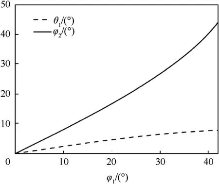
Fig.9. Deflection and reflection angle with the incident angle.
The pressure intensity at the regular oblique reflection was calculated from Eq.(9),as shown in Fig.10.The pressure intensity ratio remained stable between 2.3 and 2.4 as the incident angle increased.When the critical angle is reached,the intensity increased more quickly before surging.Therefore,by controlling the incident angle below the critical angle and stabilizing the pressure ratio at approximately 2.4,it is possible to utilize the stable overpressure to have an effect on the liner within the regular oblique reflection interval.
To obtain the distribution of the overpressure on the surface of the liner,the pressure ratio P/Pat the measurement points set on the y-axis and the midline of the liner in the finite element model were extracted from Figs.4 and 6 using the trajectory of the regular oblique reflection collision point.In Figs.11 and 12,it can be observed that when the wave front propagates along the y-axis to 30 mm,the collision point of the regular reflection comes into contact with the top of the liner,causing the pressure at the midpoint of the arc top to be the highest and then the pressure gradually decreases on both sides along the arc midline.The difference between the P/Pratios in the numerical simulation and theoretical calculation is small and both ratios demonstrate the same change trend where the maximum difference between the two is maintained below 8%;however,the amplitude of the P/Pratio in the numerical simulation is larger than that of the theoretical calculation.According to the above analysis and in combination with Fig.4,the surface of the liner was subjected to a lateral impact of the detonation wave as well as the collision of a regular oblique reflection.The pressure distribution along the radius of curvature of the liner is shown in Fig.13,which demonstrates that the front of the detonation wave first collided with the side of the liner and then propagated to the middle.The pressure in the center of the liner was the highest overpressure of the regular oblique reflection collision point,which extended to both sides before rapidly dropping.
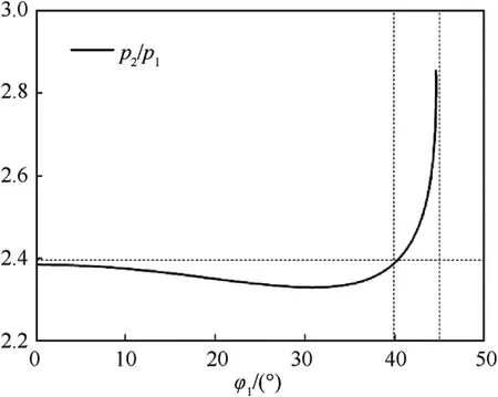
Fig.10. Intensity of the regular oblique reflection.
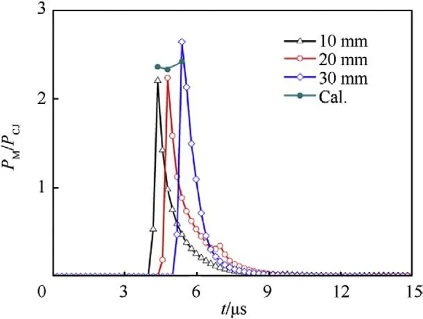
Fig.11. Pressure ratio at the collision point along the y-axis.
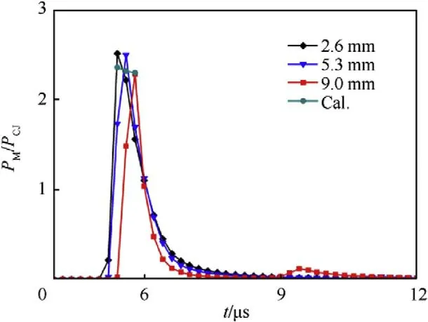
Fig.12. Pressure ratio at the collision point along the midline at the top arc of the liner.
From the pressure change in Fig.13,the pressure distribution on the surface of the liner can be determined.As shown in Fig.14,the distance from the liner midline to the boundary of the area within which the pressure ratio P/Pis greater than 2.5,2,1.5,and 1 is approximately 0.66 mm,1.32 mm,3.3 mm,and 28 mm,respectively.Therefore,the experimental results and numerical simulations demonstrate that the regular oblique reflection collision point is within the pressure region,the overpressure distribution results in a pressure gradient along the curvature radius,and the overpressure region forms the EFP head and causes the overturning of the liner.Due to the influence of the size of the elements on the numerically simulated pressure for the numerical calculation and the use of a simplified case for the theoretical calculation,there is a difference between the theoretical calculation and the numerical simulation.However,the overall analysis result for the regular oblique reflection process of the detonation wave combined with the theoretical analysis and numerical calculation for the pressure ratios demonstrate a reliable method to analyze the formation of a EFP due to the pressure action applied to the liner.
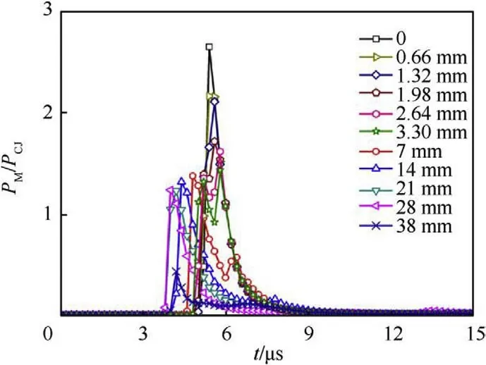
Fig.13. Pressure ratio along the radius of curvature at the top of the liner.
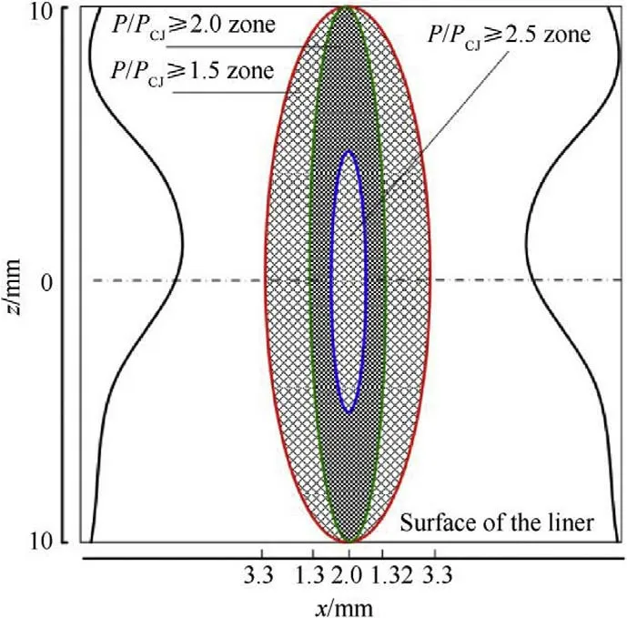
Fig.14. Overpressure distribution on the surface of the liner.
4.Results analysis
4.1.Analysis of the EFP formation process
Fig.15 shows the pressure isolines in the time sequence of the detonation wave propagating after the initiation of the two points and collision on the liner.The detonation wave propagates as an approximate spherical wave.At approximately 4 μs,the detonation wave first collides with the liner and then propagates to the middle.At 4.194 μs,the two detonation waves start to collide,and then the collision point moves along the positive direction of the y-axis,accompanied by the regular oblique collision.At 5.19 μs,the overpressure of the regular oblique reflection collision starts to act on the midline of the arc top of the liner.Due to the double curvature of the liner,the pressure of the regular oblique reflection collision point follows the radius of curvature on the surface of the liner.It can be observed that different pressure gradients are formed along the midline of the arc top on the upper surface of the liner,affecting the final formation of the subsequent EFP.At 5.79 μs,the detonation wave collision pressurization process is completed,and the pressure propagates backward after the reflected wave collision.
The three-dimensional shape and the corresponding velocity of the EFP were combined in the numerical simulation results,as shown in Fig.16,to exhibit the continuous shape changes of the EFP in the xoy and xoz planes.The effects of the overpressure caused the material at the arc top area of the liner to be more responsive to the strain.The liner turned inside out at the midline and produced a protrusion that formed the head of the EFP,which moved quickly.In the EFP flight stage,the two tails rotated around the rear of the protrusion toward the symmetry plane and united.After approximately 150 μs,the two tails gradually united and formed a flat structure,which is conducive to the EFP to maintain flight stability,increasing the aspect ratio of the EFP and thus improving the penetration ability.However,the EFP was formed with a variable cross-section in the length direction,resulting in a large width difference between the x and z directions.
During the EFP flight,the two tails rotated and then united under the traction of a velocity gradient,and the angle between the two tails was defined as α during the uniting process,as shown in the xoy plane of Fig.16.The protrusion was formed at 20 μs,but the two tails remained parallel,and the angle between the tails decreased with the increase in flight time.The tails were united at approximately 120 μs.As shown in Fig.17,the process of the angle reduction between the two tails is linear,and the two x-ray measurements were in agreement with the numerical simulation.After the closure of the tails,the velocity stabilized.The linear expression of the angle of the tail closure can be expressed as

According to the experimental and numerical simulation results presented in Table 2,the main body in the middle of the EFP was thick,and there was radial expansion between the main body and the tail.The massive rear part appears behind the slug in the x-ray image for the angle of 55.The pressure distribution on the surface of the liner in Fig.14 of the original manuscript indicates that the pressure gradient associated with the pressure distribution on the Rarc is considerably smaller than that on Rduring the overturning of the center of the double-curvature liner.Consequently,the material turnover speed in the xoz plane is lower than that in the xoy plane,as evident in Fig.16.Therefore,the massive rear part shown in the x-ray image for the angle of 55is the result of overturning and stretching around the x axis of the high-ductility oxygen-free copper material at the top of the arc.In the simulation,the ALE algorithm was used for the liner and air domain,and element formulation was used for the one-point ALE multimaterial element,which can contain many types of materials.Therefore,the ALE algorithm can be effectively used for large deformation problems,but it is not very accurate for tracking the movement of the material boundary.Consequently,the local boundary of the small separated EFP materials could not be fully captured and displayed.The characteristics of the EFP shape,speed,and tail closing angle were determined in both the experiential tests and numerical simulations,further illustrating that the establishment of a numerical model can effectively reflect the formation process of an EFP from a unit charge.
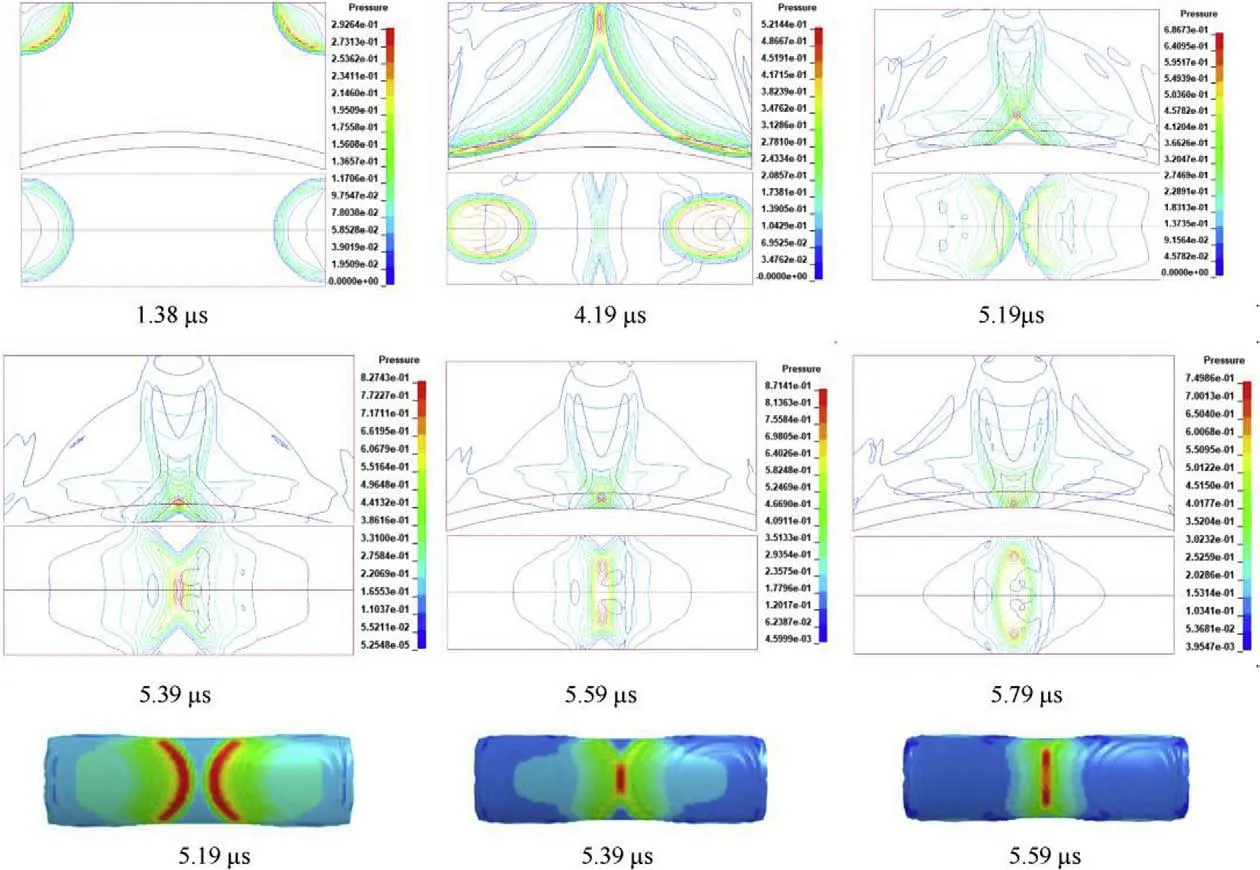
Fig.15. Pressure isolines of the detonation wave in time sequence (unit:100 GPa).
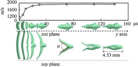
Fig.16. Evolution of the shape of the projectile during the early formation stages.
4.2.Analysis of the results of the penetration experiments
The physical entity of the unit-shaped charge is shown in Fig.18,and the size of the shaped charge is consistent with the finite element model.In the experimental layout shown in Fig.19,the size of the target was 0.5 m×0.5 m×0.03 m.The unit charge was placed vertically on the support with a stand-off distance of 300 mm.The thin copper wire coil device for speed measurements was arranged between the target and charge,and a synchronous device was used to control the initiation synchronicity error within 1 μs to diminish the effect of the initiation deviation.
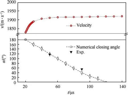
Fig.17. Tail closing angle of the EFP and corresponding speed.
The results of the experiments and numerical simulations to determine the EFP penetrating capability into the target are shown in Fig.20.
According to the morphology of the target in the two experiments,the EFP was folded and closed before penetrating the target,in which the dimensions of the holes were approximately 27 mm×16 mm and 30 mm×19 mm,respectively,and there was an obvious round protuberance on the back of the target,due to the favorable ductility of 45#steel,and the back of the target directly in contact with the rigid concrete surface.Although the penetration ofthe EFP failed to completely penetrate the target due to the fine ductility of the target,the penetration depth exceeded the thickness of the target.The numerical simulation results indicate a frontal penetration morphology and isolines of an effective plastic strain of the back protrusion,similar to the experimental results.The corresponding results are listed in Table 3.

Table 2 Comparison of X-ray test and numerical simulation results.

Fig.18. Entity of the unit-shaped charge with the liner.
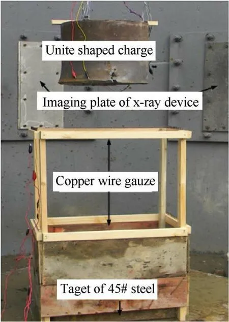
Fig.19. Experimental arrangement.
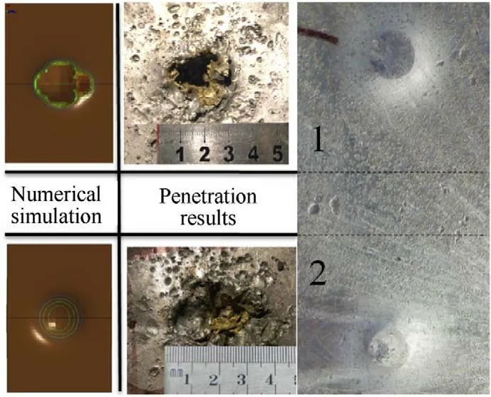
Fig.20. Penetration and numerical results of the EFP.
The larger the protrusion diameter,the better the closure of the formed tails and the higher the speed of the EFP penetration.In general,the entire penetration process was performed by the head of the EFP in front of the tail.The radial expansion between the head and the tail increased the resistance during the penetration process.
5.Conclusion
1.By designing the size of the charge and liner,the incidence angle was close to the critical angle,and the pressure ratio in the area of the collision point was greater than 2.4.The detonation collision was controlled to be within the region of the regular oblique reflection,and a stable overpressure in this region was applied to act on the liner.The pressure of the regular oblique reflection collision point acted on an area instead of a point.

Table 3 Penetration data.
2.The pressure distribution on the surface of the liner was studied.The distance from the liner midline to be boundary of the area within which the pressure ratio of the P/Pwas greater than 2.5,2,1.5,and 1 was approximately 0.66 mm,1.32 mm,3.3 mm,and 28 mm,respectively;therefore,a pressure gradient was generated on the surface of the liner.
3.For the unit-shaped charge and the double curvature liner,the formation process of the EFP after the two points of initiation was analyzed.The EFP first turned inside out in the middle to form the head as the main body and the two tails of the EFP united to a reach a closed state,forming the penetrator at approximately 120 μs.
4.The radial expansion between the head,and tail increased the resistance during the penetration process.Therefore,it is necessary to further optimize the structural size of the unitshaped charge to reduce the size of the area between the head and tail.
The authors declare that they have no conflict of interest.
The work presented in this paper has been supported by the science foundation (YT20-01-02) of Nanjing Vocational University of Industry Technology and the National Science Foundation of China under NO.11802141.
- Defence Technology的其它文章
- Defence Technology
- Performances and direct writing of CL-20 based ultraviolet curing explosive ink
- One-step synthesis of FeO(OH) nanoparticles by electric explosion of iron wire underwater
- Driving force coordinated control of an 8×8 in-wheel motor drive vehicle with tire-road friction coefficient identification
- Monitoring and Prediction of the Vibration Intensity of Seismic Waves Induced in Underwater Rock by Underwater Drilling and Blasting
- Effects of Mg/PTFE pyrotechnic compositions on reignition characteristics of base bleed propellants and heating mechanism

