An ultra-wideband 2-bit coding metasurface using Pancharatnam-Berry phase for radar cross-section reduction
Bao-Qin Lin(林寶勤), Wen-Zhun Huang(黃文準(zhǔn)), Lin-Tao Lv(呂林濤), Jian-Xin Guo(郭建新),Yan-Wen Wang(王衍文), and Hong-Jun Ye(葉紅軍)
School of Information Engineering,Xijing University,Xi’an 710123,China
Keywords: coding metasurface,Pancharatnam-Berry phase,radar cross-section(RCS)
1. Introduction
Metasurface is a kind of 2D planar metamaterial, which is an artificial composite surface composed of sub-wavelength resonant unit cell structures. Through the reasonable design of the unit cell structures, almost all the basic properties of electromagnetic (EM) waves can be tailored by using various metasurfaces. Due to the favorable characteristics of metasurfaces, a variety of metasurfaces, such as metasurface absorbers,[1-5]artificial magnetic conductors(AMC)[6-11]and coding metasurfaces[12-30]have been proposed to reduce the radar cross-section(RCS)of stealth targets.
The firs coding metasurface was proposed by Cuiet al.in 2014,[12]which consisted of several different types of coding elements arranged at random. Because the reflection phases in various types of coding elements were very different, the coding metasurface could achieve broadband RCS reduction due to phase cancelation after optimizing the arrangement of these elements.In a coding metasurface,the type of coding elements can be represented as a binary digit according to their different phase responses. For example, for a 2-bit coding metasurface, the codes “00”, “01”, “10”, and “11” can represent the coding elements with relative phase responses 0°,90°, 180°, and 270°, respectively. Therefore, the array pattern of a coding metasurface can be represented by a coding sequence,and based on several proper coding elements,a desired coding metasurface can be proposed by optimizing the coding sequence. Based on the above, we know that the design procedure of a coding metasurface will mainly consist of the following two steps:one is to design several proper coding elements with suitable phase responses,and the other is to obtain an appropriate coding sequence.In recent years,to realize broadband RCS reduction, coding metasurface has attracted significant attention and many different designs have been proposed. The simplest case is 1-bit coding metasurface,[13-19]which consists of only two types of elements denoted as ‘0’and ‘1’. When the reflection phase difference between 0 and 1 elements can be maintained between 180+37 in a specific frequency range,10-dB RCS reduction will be realized in the band due to phase cancelation. In Refs.[20-23],a series of 2-bit coding metasurfaces have been presented. For a 2-bit coding metasurface composed of four types of elements with relative reflection phases 0°,90°,180°,and 270°,it can be seen as a combiner of two different 1-bit coding metasurfaces Thus,it can achieve greater freedom for controlling EM waves. When the four types of elements are arrayed according to an appropriate coding sequence,it displays better performance in RCS reduction.[12]
In this work, to design an ultra-wideband 2-bit coding metasurface for RCS reduction using Pancharatnam-Berry(PB) phase, a polarization conversion metasurface (PCM) is first proposed. The simulated results show that the PCM can make the magnitude of its co-polarized reflection coefficient under CP incidence close to 1.0 in the ultra-wide frequency range from 9.8 GHz to 43.3 GHz,and when the metallic patch in its unit cells is rotated by an angleψ, almost±2ψPB phase will be generated in the co-polarized reflection coefficient. Thus, based on the PCM, an ultra-wideband 2-bit PB coding metasurface is successfully proposed. The simulated and experimental results show that the coding metasurface can realize RCS reduction under arbitrary polarization incidences.Moreover,its working band(9.8 GHz to 42.6 GHz)is almost the same as that of the original PCM(9.8 GHz to 43.3 GHz).
2. Design and analysis of the coding elements
To design a reflective 2-bit coding metasurface,four coding elements with relative reflection phases of 0°, 90°, 180°and 270°need to be constructed. In this work, to construct the four appropriate coding elements using PB phase,an ultrawideband PCM is first proposed,which consists of a metallic patch array printed on the top of a dual-layer grounded dielectric substrate. One of its unit cells is shown in Fig. 1. It can be seen that the metallic patch in the unit cell is a circular structure, which is most suitable for rotation to generate PB phase. Moreover, the metallic patch is an anisotropic structure with a pair of symmetric axesuandv, which are perpendicular to each other. We define the angle between the positiveu-axis and positivex-axis as the rotation angleψo(hù)f the metallic patch, now the metallic patch has been rotated byψ=45°. In addition, the geometrical parameters of the unit cell structure are shown in Fig. 1. After appropriate selection, the following geometrical parameters were chosen:P=6.00 mm,r=2.60 mm,w=0.20 mm,g=1.40 mm,t=0.20 mm,α=38°,h1=0.50 mm andh2=2.00 mm. In addition,the metallic patch,together with the grounded plane,is modeled as a 0.017-mm copper film with electric conductivityσ=5.8×10⁷S/m. Moreover, the dual-layer dielectric substrate consists of a PTFE dielectric layer and foam layer,whose relative permittivities areεr1=1.80 andεr2=1.05,respectively.
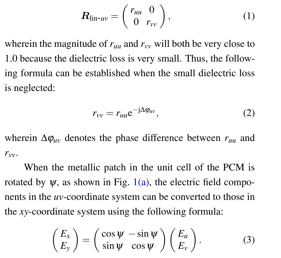
Due to the symmetry of the PCM structure, in theuvcoordinate system, the reflection matrixRlin-uvfor a linearly polarized(LP)wave can be expressed as
Thus,the reflection matrixRlin-xyin thexy-coordinate system can be obtained through the following formula derivation:
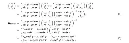
When the proposed PCM is under CP normal incidence,since the CP incident wave is in-zaxis direction,the unit waves of the right-handed CP(RCP)incident and left-handed CP(LCP)reflected waves are both expressed as ?ei+= ?er-= ?ex+j?ey. However,those of the LCP incident and RCP reflected waves are expressed as ?ei-= ?er+= ?ex-j?ey. Thus,the reflection matrixRcirfor CP wave can be derived as follows:


Equation(7)illustrates that when the metallic patch in the unit cell of the PCM is rotated by an angleψin an anticlockwise direction,the PB phases generated inr++andr--will be+2ψand-2ψ, respectively. However, the phase ofr+-andr-+will not be altered. Therefore, to design a reflective coding metasurface using PB phase,it must be based on an appropriate PCM,which can make the magnitude ofr++andr--close to 1.0. Moreover,according to Eq.(7),the magnitudes ofr++,r--andr+-,r-+can be expressed as

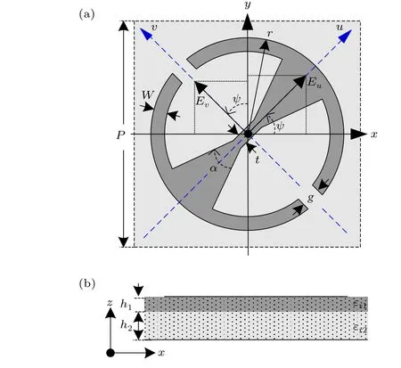
Fig.1. Unit cell structure of the proposed PCM:(a)top view,(b)side view.
Equation(8)indicates that the polarization conversion performance of the PCM can be determined by the phase difference Δφuvbetweenruuandrvv. When the phase difference|Δφuv|is close to 180°,the magnitudes ofr++andr--will be close to 1.0, and the anticipated CP-maintaining reflection can be realized.CST Microwave Studio. First,it has been simulated underuandv-polarized incidences. The simulated results, shown in Fig.2(a),indicate that the phase difference Δφuvof the PCM is close to 180°in the ultra-wide frequency range from 10 GHz to 43 GHz. In addition, according to the phase differences Δφxyin Fig. 2(a), the magnitudes ofr++andr-+have been calculated using Eq. (8). The calculated results, as shown in Fig. 2(b), indicate that the magnitude ofr++is approximately 0 dB,however,that ofr-+is kept less than-10 dB in the ultra-wide frequency band of 9.8 GHz-43.3 GHz, which shows that the anticipated CP-maintaining reflection will be realized in the ultra-wide band with a relative bandwidth of 126.2%. Furthermore,in order to verify the calculated results,the metasurface has been simulated under RCP incidence. In Fig.2(b),it is shown that the calculated and simulated results are in good agreement with each other.
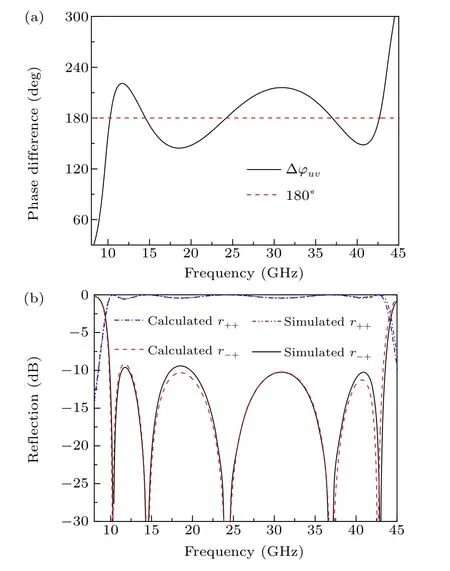
Fig.2. Simulated results of the proposed PCM:(a)phase difference between ruu and rvv,(b)magnitude of r++ and r-+.
In order to analyze the performance of the proposed PCM,we have carried out a series of numerical simulations using
Moreover,to verify that PB phase will be generated in the co-polarization reflection coefficientsr++andr--by rotating the metallic patch in the unit cell of the proposed PCM, the PCM has been repeatedly simulated under RCP and LCP incidences when the rotation angleψo(hù)f the metallic patches in its unit cells was gradually increased from 0°to 157.5°with a 22.5°step width. The simulated results,shown in Figs.3(a)and 3(b), indicate that along with the increase of the rotation angleψ, the phase ofr++keeps increasing gradually but the phase ofr--keeps decreasing gradually in the ultra-wide frequency range from 8 GHz to 44 GHz,and they are both altered by almost 45.0°each time, which verifies that when rotation angleψis increased by Δψ, the PB phases generated inr++andr--will be+2Δψand-2Δψ,respectively.
According to the simulated results in Fig. 3, it is known that when rotation angleψo(hù)f the metallic patches in the PCM is gradually increased from 0°to 157.5°with a 22.5°step width,the PCM can always be used as coding elements of the coding metasurface. Based on the relative reflection phases of the PCM under RCP incidence,the code of the PCM at different states is listed in Table 1. It is shown that the PCM can be used to design 1-, 2-, and 3-bit coding metasurfaces. In this work, to design a 2-bit coding metasurface, the four coding elements,whose codes are“00”,“01”,“10”,and“11”,respectively, can be chosen as the PCM at the four states, wherein the rotation angleψo(hù)f the metallic patches are 0°, 45°, 90°,and 135°,respectively.
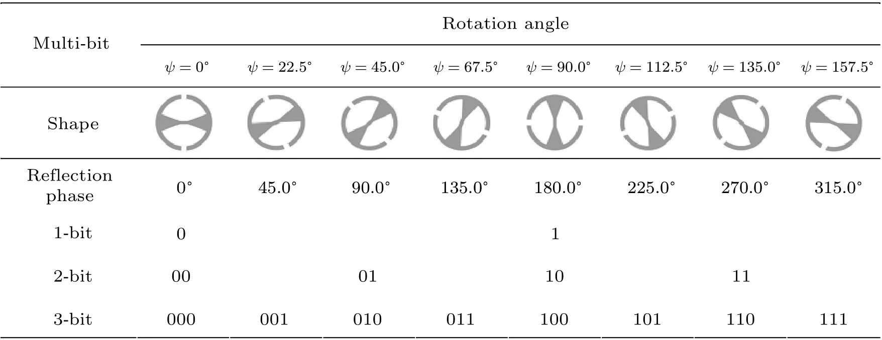
Table 1. The relationship between the PCM at different states and 1-,2-,and 3-bit coding metasurfaces.

Fig.3. Simulated results of the proposed PCM when the metallic patches in its unit cells are with different rotation angles ψ: (a)phase of r++,(b)phase of r--.
3. Design and analysis of the 2-bit coding metasurface
After the four coding elements were constructed, a 2-bit coding metasurface was proposed according to an appropriate coding sequence obtained by repeated simulations. The proposed 2-bit coding metasurface, shown in Fig. 4, consists of 6×6 coding elements,and each coding element is composed of 5×5 sub-unit cells. For the 2-bit coding metasurface, the reflection amplitudes in different elements are basically the same, but the reflection phases are different. The reflection phase difference between “00” and “10”, together with that between “01” and “11”, will be close to 180°. Thus, the anticipated RCS reduction can be realized due to the phase cancelation because these elements are arrayed according to an appropriate coding sequence.
To show the RCS reduction performance of our design,the 2-bit coding metasurface, together with a pure metallic plate of the same size, has been simulated under RCP, LCP,x-polarized(XP)andy-polarized(YP)normal incidences successively. The obtained simulated results, the mono-static RCSs of the coding metasurface and the metallic plate, are shown in Fig. 5(a), in which it is shown that the monostatic RCS of the coding surface is almost the same under different polarization incidences, and the RCS is significantly reduced compared with that of the metallic plate. In addition,in Fig.5(b),it is shown that under all incidences,the RCS reduction of the coding metasurface relative to the metal plate is kept larger than 10 dB from 9.8 GHz to 42.6 GHz except for 11.8 GHz to 12.6 GHz wherein RCS reduction is more than 8.4 dB,and the relative bandwidth reaches 125.2%.Moreover,the maximum RCS reduction under RCP,LCP,XP and YP normal incidence reaches 35.8 dB,39.2 dB,35.9 dB,and 39.7 dB, respectively, at 38.6 GHz. These simulated results indicate that the coding surface has the obvious advantages of wideband and polarization-insensitivity,it can realize ultra-wideband RCS reduction under arbitrary polarization incidences.
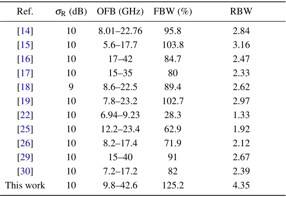
Table 2. Comparison of this work with previous works.
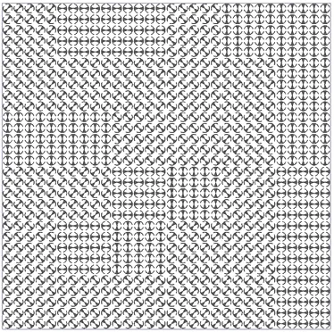
Fig.4. Schematic diagrams of the proposed 2-bit coding metasurface.
Furthermore, to show far-field scattering characteristics of the 2-dit coding metasurface,the far-field scattering patterns of the coding metasurface and the metallic plate of the same size under LCP,RCP,XP and YP normal incidences were obtained at 10.0 GHz,25.0 GHz,and 40.0 GHz through far-field simulation. The simulated results, shown in Fig. 6, indicate that compared with the strong specular reflection of the metal plate,the scattering field of the coding metasurface is diffused to all directions of the space in the specular reflection region.In addition,the far-field scattering characteristics of the coding metasurface are basically the same under LCP, RCP, XP and YP normal incidences,the bistatic RCS of the coding metasurface in most directions is reduced under different polarization incidences.
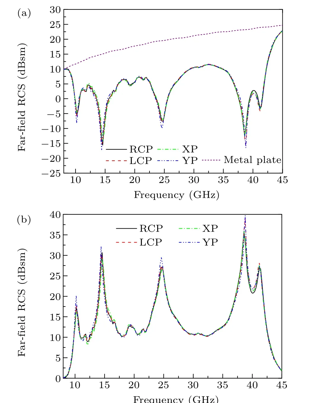
Fig. 5. Simulated results of the coding metasurface and the metallic plate:(a)monostatic RCS,(b)RCS reduction of the coding metasurface.
Finally, to experimentally verify the performance of the 2-bit coding metasurface,one laboratory sample has been fabricated using standard print circuit board (PCB) technique,which is shown in Fig.7(a). The laboratory sample has been measured by the free space method. In addition,a metal plate of the same size has been measured in the same way as a reference. The measurement has been carried out under RCP,LCP,XP and YP normal incidences successively. The measured results are shown in Figs. 7(b) and 7(c). It is shown that the measured results under RCP and LP incidences are almost the same. In addition, the measurement results are in reasonable agreement with the simulated results,although there is a slight deviation caused by fabrication and measurement errors.

Fig. 6. Simulated 3D far-field scattering patterns of the proposed coding metasurface and the metal plate under different incidences at (a) 10.0 GHz, (b)25.0 GHz,and(c)40.0 GHz.

Fig.7. Photographs of the experimental sample(a)and comparison of simulated and measured RCS reduction under RCP,LCP incidences(b)and XP,YP incidences(c).
4. Conclusion
In this paper, an ultra-wideband 2-bit PB coding metasurface was proposed based on an ultra-wideband PCM. The simulated results show that the RCS of the coding metasurface under arbitrary polarization incidences can be reduced by more than 10 dB RCS relative to a metallic plate of the same size in the frequency band from 9.8 GHz to 42.6 GHz except for 11.8 GHz to 12.6 GHz,and the relative bandwidth can be up to 125.2%. In addition, the coding metasurface has been successfully fabricated and measured, and there is a reasonable agreement between the simulated and measured results.Table 2 lists a comparison of the proposed coding metasurface with previous works. It is indicated that the coding metasurface has a significant advantage in the bandwidth expansion of RCS reduction. Moreover, the coding metasurface is polarization insensitive,so it has great application value in radar stealth technology application.
Acknowledgments
Project supported by the National Natural Science Foundation of China (Grant No. 62072378), the Natural Science Foundation of Shaanxi Province, China (Grant No. 2019JM-077), and the Xi’an Science and Technology Plan Project,China(Grant No.GXYD20.4).
- Chinese Physics B的其它文章
- Measurements of the 107Ag neutron capture cross sections with pulse height weighting technique at the CSNS Back-n facility
- Measuring Loschmidt echo via Floquet engineering in superconducting circuits
- Electronic structure and spin-orbit coupling in ternary transition metal chalcogenides Cu2TlX2(X =Se,Te)
- Characterization of the N-polar GaN film grown on C-plane sapphire and misoriented C-plane sapphire substrates by MOCVD
- Review on typical applications and computational optimizations based on semiclassical methods in strong-field physics
- Quantum partial least squares regression algorithm for multiple correlation problem

