Buckling of composite cylindrical shells with ovality and thickness variation subjected to hydrostatic pressure
Zhun Li , Ke-chun Shen ,c,*, Xin-hu Zhang , Guang Pan
aSchool of Marine Science and Technology, Northwestern Polytechnical University, Xi'an, 710072, China
bKey Laboratory for Unmanned Underwater Vehicle, Northwestern Polytechnical University, Xi'an, 710072, China
c Structural Ceramics and Composites Engineering Research Center,Shanghai Institute of Ceramics,Chinese Academy of Sciences,Shanghai,200050,China
Keywords:Composite Cylindrical shell Buckling Hydrostatic pressure Imperfections
ABSTRACT The initial geometric imperfection is one of the primary factors affecting the buckling behaviors of composite cylindrical shells under hydrostatic pressure.In this study,ovality and thickness variations as two representative types of the geometric imperfections are considered.After measuring the geometric imperfections, a typical carbon fiber reinforced polymers (CFRP) cylindrical shell is tested to obtain the buckling pressure.The buckling behaviors of the shell sample are analyzed in combination with the strain responses.By using the nonlinear numerical analysis, the buckling shapes of the CFRP cylinder shells with different combinations of ovality and thickness variation are firstly discussed.The rules of influence of such imperfections on the buckling pressure are then obtained by nonlinear regression method.Finally, an empirical formula is proposed to predict the buckling pressure of the composite cylinder shells, and the calculated results from the formula are in good agreement with the numerical results.
1.Introduction
The composite materials have very wide application in the structural fields of aviation,aerospace and marine areas.Due to the outstanding characteristic of low density, high strength and good corrosion resistance, more and more composite structures are designed to replace the traditional metal structures[1].The carbon fiber reinforced polymers (CFRP) composite materials which consist of carbon fibers and resin matrix have been used to construct the pressure shells of underwater vehicle for decades[2].As underwater vehicles operate normally in deep water, the pressure shells require sufficient strength and stability to resist the external hydrostatic pressure around [3].The cylindrical pressure shell is the common structure in underwater vehicle.Previous researches [4-7] have informed us that the high external pressure will lead to the buckling of the pressure shell, which is a direct threat to the operational safety of underwater vehicle.Therefore,buckling must be taken into consideration carefully in the design of composite pressure shell.
However,the buckling behaviour of composite pressure shells is influenced by many factors, in which the geometric imperfections are the most influential [8-11].The definition of the geometric imperfections is the shape deviations from the ideal structure.For composite cylinders under hydrostatic pressure, Moon and Hur[12,13] found that the buckling pressures predicted by numerical simulations have a deviation of more than 20% with the experimental results due to neglecting the geometric imperfections.Eigenmode imperfection approach [14] is the most common method to study the effects of geometric imperfections on loaded structures.Petreli [15] introduced different eigenmode imperfections to composite cylinder shell.The results showed that the buckling pressure is closely associated with the shape and the amplitude of the imperfections.Based on a large number of experiments, NASA [16] presented empirical knockdown factors to consider imperfections when designing the cylinder shell, but the design guidelines were later proved to be very conservative [17].Yoon[18]recently proposed an empirical formula in predicting the collapse load of composite cylinder under hydrostatic pressure, a reduction factor deduced from the experiment results is involved in taking the manufacturing imperfections into account.The highfidelity shell model including the geometric imperfections can be established by using the three dimensional contact measurement[19], but this method is not suitable for industrial purposes which require fast and simple design guidelines [20].
The CFRP cylindrical shells are generally manufactured by the filament winding method or hand-layup method on a built mandrel.The machining accuracy of the metal mandrel greatly affects the quality of the composite structure.The problem of ovality is a very common in cylinder shell structures, such as subsea pipelines [21,22].Mcmurray [23] found that the minor diameter is the primary effect for laterally pressurized elliptical composite cylinders.The buckling pressure of the elliptical cylinder is only approximately 60% of the equivalent circular cylinder [24].Therefore,as an extension study,taking the ovality as the geometric imperfections for composite shells is of certain actual engineering significance.
The fiber crossing will lead to thickness waviness in the fabrication process of the composite laminated cylinder shell [25],which appears as thickness variations.An analytical method for elastic buckling of metal cylinder shell with arbitrary thickness variations under lateral pressure was proposed by Feng [26].Messager [27] presented a modified equilibrium equation to calculate the linear buckling pressure of the laminated cylinders with axisymmetric thickness.The results showed that the thickness variation can significantly reduce the buckling pressure.Hutchinson [28] found that, like circular cylinders, the axial compressed oval cylinders are also highly sensitive to geometrical imperfections and may buckle much lower than the perfect shell.After axial compression tests on a series of oval cylinder shells,Kempner[29]found that the cylinder with large ovality is less sensitive to the imperfections than the moderate oval and the circular cylinder.For a real CFRP cylindrical shell, the ovality may possibly coexist with the thickness variation.However, there are no reports and literature of the relevant studies on such imperfect composite laminated cylindrical shells under hydrostatic pressure.
Accordingly,this paper focuses on the buckling behaviors of the laminated composite cylinder with the ovality and the thickness variation.After measured the geometric imperfections,a composite cylinder model with the layup of[90(±80)(±40)90]is tested to investigate the buckling characteristic.The composite cylinder with different combinations of ovality and thickness variation are studied by nonlinear finite element analysis.The simulation results are analyzed to deduce a formula in predicting the buckling pressure of the imperfect composite cylindrical shells.The proposed formula is compared with the experimental result and FEA results.
2.Experimental analysis
2.1.Mechanical performance test
A typical composite cylindrical shell was manufactured by Shaanxi Eagle Equipment Technology Limited Company (SEET) by using CFRP laminate, the 7075 aluminum alloy flanges were bonded to the both ends of the shell by a hardening adhesive.The composite shell has a nominal inner diameter of 200 mm, a nominal shell thickness of 5 mm and a total length of 430 mm (see Fig.1).The stacking sequence of the shell is [90(±80)(±40)90], where 90 refers to the circumferential winding layer.
The mechanical tests were conducted to obtain the main mechanical parameters of the CFRP laminate.A total of twenty CFRP laminate specimens were manufactured by the same manufacture of the composite shell.The specimens were divided into four groups, the tensile and compression tests of 0, the compression tests of 90and the shear tests of 45.The thickness and the width of each numbered specimen at any three positions were measured by the vernier caliper, and the average value was used to calculate the cross section area.A type of UTM5105 computer-controlled electronic universal testing machine was used to perform the test,and the loading speed was set to be 2 mm/min.The tensile test,the compression test and the shear test were conducted according to the ASTM D3039, ASTM D6641 and ASTM D3518, respectively.The horizontal and the vertical strain gauges were placed at the surface of each sample (see Fig.2).All the mechanical tests were performed in the National Laboratory of dynamics and structural strength, School of Mechanics, Civil Engineering and Architecture,Northwestern Polytechnical University.
The failure load of each specimen can be determined from the recorded load-displacement curves in Fig.3, the ultimate strength can be calculated with the measured geometry data in Table 1.Combing with the strain,the elastic modulus and the Poisson ratio can be determined.The failure of each group are shown in Fig.4,it can be seen that the failure mode of the tensile test is longitudinal explosion of fiber, the failure mode of the compression test is typical compression failure through thickness, the failure mode of the shear test is gradual separation between fibers.According to the assumption proposed by Moon [12], when the delamination was not considered, the transverse properties in 1-3 plane is considered same as in 1-2 plane and the transverse shear propertiesis 80% of.So the present material properties of the CFRP are listed in Table 2,and these values were used for the finite element analysis in this study.
2.2.The definition of the ovality and the thickness variation
The cross section of a cylindrical shell with the form of ovality is shown in Fig.5(a),the definition of the ovality(Δ)is as follows[21]:

whereandrepresent the maximum and the minimum outer diameters of the shell, respectively.The magnitude of the ovality was assumed to be constant over the length in this paper to simplify this problem.The radial deviation(δ)between the cylinder with ovality and the perfect cylinder is expressed as follows(taking the inward direction as negative):

where θ is the polar angle andis the mean radius.It can be seen that a cylindrical shell with the ovality can be modeled as an elliptic cylinder with the semi axis of(1 + Δ) and(1-Δ), respectively.The mean radius of the elliptic cylinder () as follows:

The cross section of a cylindrical shell with the thickness variation is shown in Fig.5(b),the definition of thickness variation(ω)is as follows [21]:

whereandrepresent the maximum and the minimum shell thicknesses, respectively.Similarly, the magnitude of the thickness variation was considered as constant along the shell length in this paper.The variation of shell thickness in circumferential direction as following:
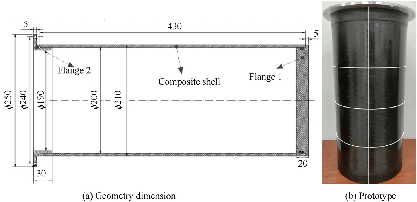
Fig.1.The composite cylindrical shell.
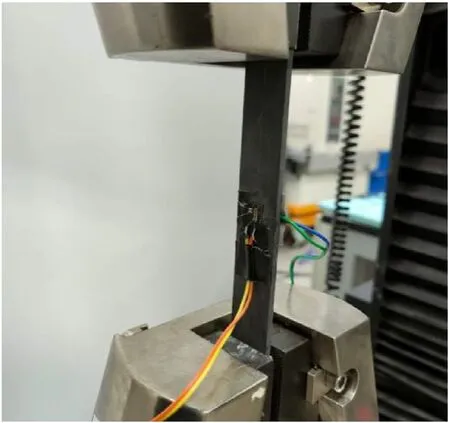
Fig.2.The mechanical test of CFRP laminate specimen.

where δis the thickness variation parameter andθ is the shell thickness in radial direction.The relationship between the thickness variation (ω) and thickness variation parameter (δ) in this study is as follows:

Therefore, a cylindrical shell with thickness variation can be modeled by two non-concentric circles with the distance of δbetween them.
When the ovality and thickness variation were both considered,the orientation of thickness variation was also discussed.Suppose the direction of the ovality is horizontal, it is called TVY when the thickness variation is in Y-direction,as shown in Fig.6(a).And it is called TVX when the thickness variation is in X-direction,as shown in Fig.6(b).According to the previous studies [21], the range of ovality is set from 0 to 1%,while the range of thickness variation is set from 0 to 40% in this paper.
2.3.Measurement of geometric imperfections
As the geometric imperfections in shell are generally nonuniform, the geometric dimensions of the present composite shell in the middle length were measured before the pressure test.The internal radius and the shell thickness were measured by specially designed internal micrometer and thickness gauge.A total of 24 measurements points with an interval of 15were selected, the measured data in Fig.7 show that the deviations of the internal surface are smaller than the external one,it is because the internal surface contacts with the mandrel during the manufacturing.Meanwhile, the ultrasonic scanning technology was also used to detect the imperfections inside the shell.Fig.8 (a) shows the scan results of one cross section,where the two up-and-down red zones represent the internal and external interface of the shell.The imperfections inside can change the signal wave thus making the incomplete reflection in the bottom.The complete scan results of the bottom reflection are shown in Fig.8(b),it can be clearly seen a strip blue area between 180and 270, which may indicate the existence localized geometric imperfections,delaminations or fiber misalignment inside.However,the form and the magnitude of the imperfections are hard to be determined due to the technical reasons.
2.4.Hydrostatic test
The hydrostatic test was performed at Key Laboratory for Unmanned Underwater Vehicle, Northwestern Polytechnical University.As shown in Fig.9, the test system consists of three major parts: hydraulic system of the water pressure, dynamic strain measurement and the hydrostatic chamber.The open flange of the shell was in fixed connection with the outer flange of the chamber by screws.In order to capture the buckling load as accurately as possible, five stages of water pressure was set during the experiment.The detail of the test conditions are given in Table 3.As shown in Fig.10,six biaxial strain gauges were placed in the inner surface of the composite shell to measure the strain response.Four strain gauges were evenly placed in the middle length of the shell along the circumference, and the other two strain gauges were placed near the ends of the shell.
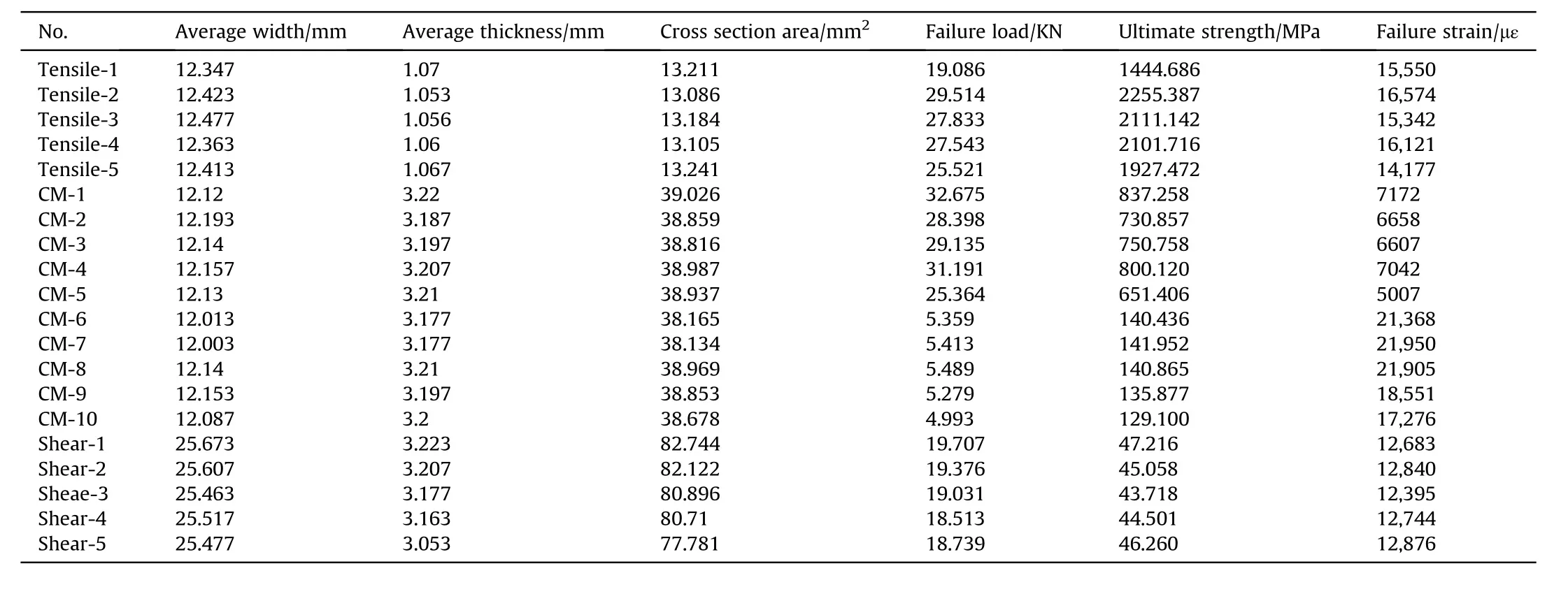
Table 1 The data table of the sample specimens.
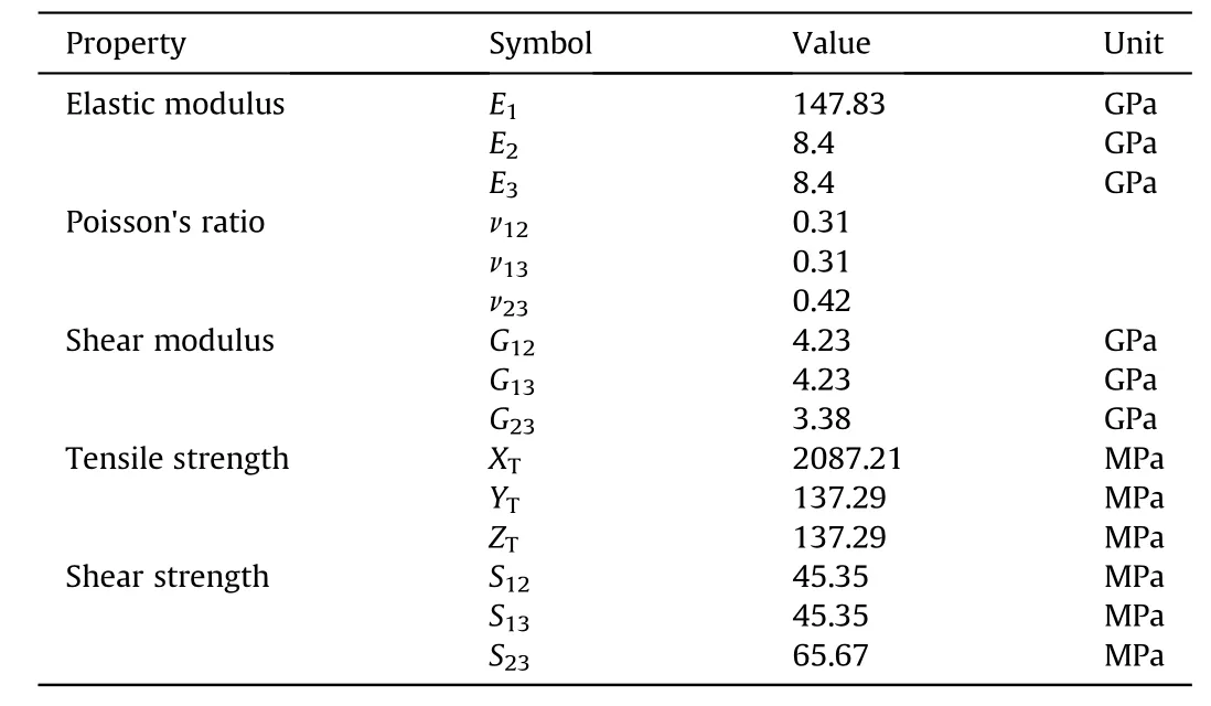
Table 2 The calculated mechanical properties of the CFRP.

Table 3 The test conditions.
The strain responses of the six strain gauges in the hoop direction and in the axial direction are shown in Fig.11,respectively.The strain data can give useful information to understand the buckling behaviour of the shell during the experiment.For the measured data in the hoop direction, it can be seen that the magnitudes of compressive strains of strain gauge-1,3,5 and 6 increase proportionately with the increasing of water pressure.But the strain response of strain gauge-2 and 4 change dramatically with the hydrostatic pressure being increased.For the strain gauge-2,the magnitude of compressive strain increases sharply when the water pressure increases from 8 MPa to 9 MPa, it implies that the outward bulges near the strain gauge-2 gradually develop as the pressure increases to 9 MPa.For strain gauge-4, the magnitude of compressive strain drops abruptly almost to 0 when the water pressure increases from 6 MPa to 8 MPa.And when the water pressure increases from 8 MPa to 9 MPa, the compressive strain becomes tension strain as the strain value changes from negative to relatively large positive.It implies that the region near the strain gauge-4 changes from compressive state to inward depressions gradually.For the measured data in the axial direction, it can be seen that the magnitude of compressive strain of strain gauge-4 is bigger than that of other strain gauges, which can attribute to the relatively thin wall thickness.Due to the boundary conditions, the magnitude of compressive strain of strain gauge-1 in both direction are smaller than other strain gauges.By contrast,the magnitudes of compressive strains in hoop direction are smaller than those in axial direction,it shows that axial stiffness of this composite shell is weaker than the hoop stiffness.
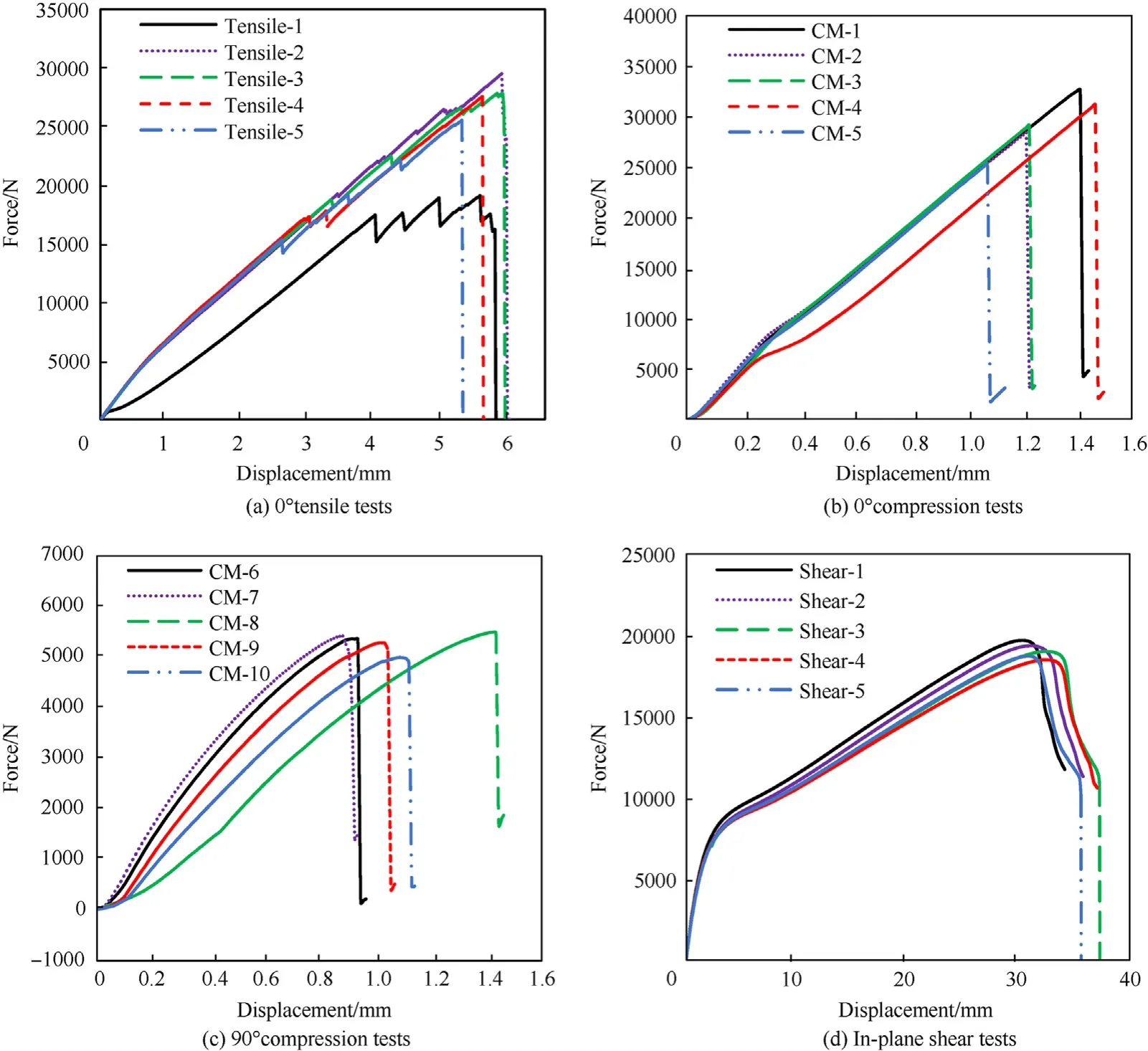
Fig.3.The load-displacement curves of each specimen.
The final failure of the composite shell is shown in Fig.12, two orthogonal cracks appear in the middle lower part of the shell from outside view.The hoop crack accounts for 60%of the perimeter and the axial crack accounts for 30% of the total length.A number of broken carbon fibers can be seen along the hoop direction from internal view.The bending of the shell in circumferential direction can explain such failure phenomenon.The hydraulic control system recorded the maximum water pressure of 9.18 MPa.
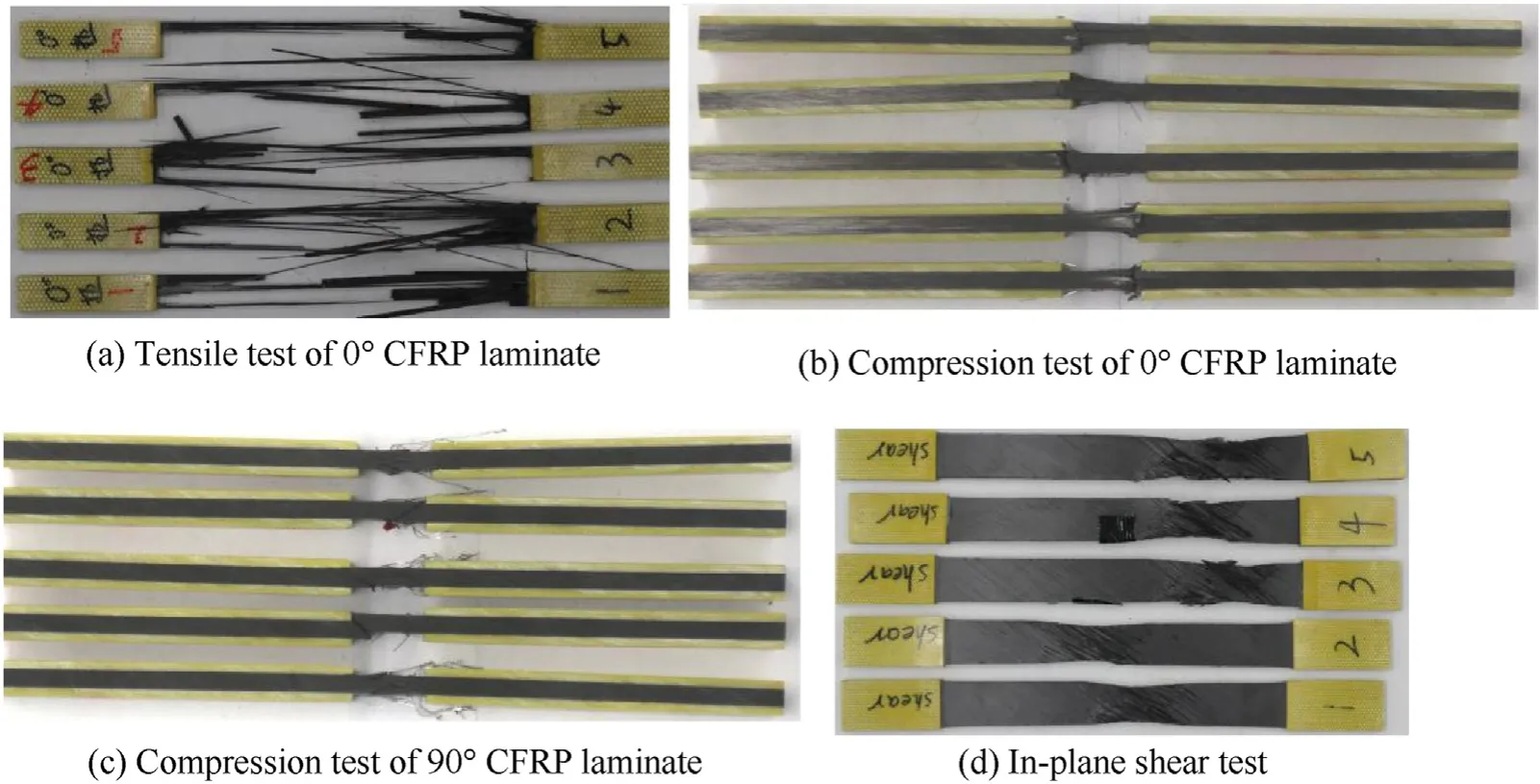
Fig.4.The failure picture of the specimens.
3.Numerical calculation
3.1.FE model
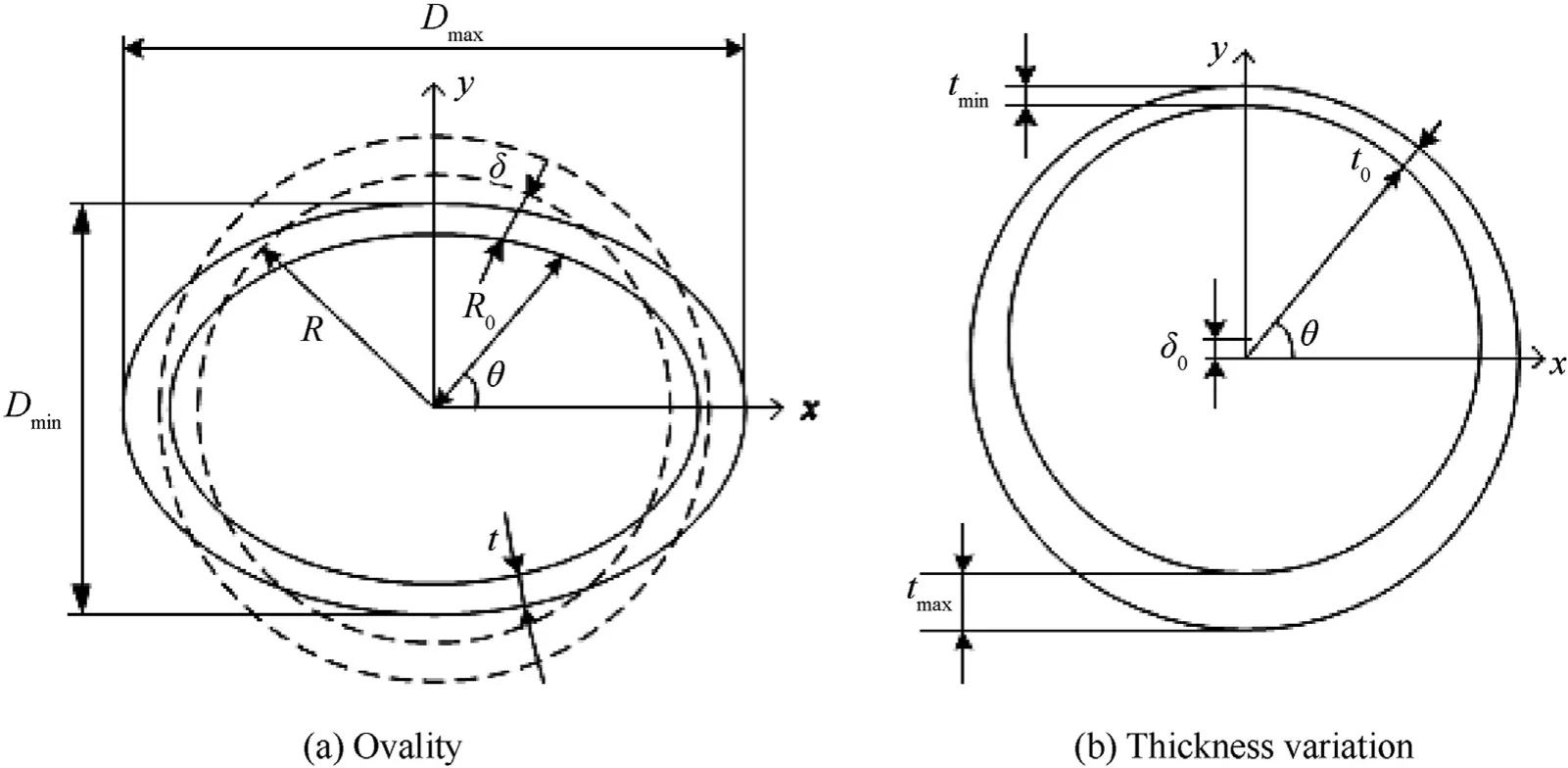
Fig.5.The cross section of cylindrical shell with imperfections.
The finite element method was used to predict the buckling behaviour of the imperfect shell in this paper.The FE models were developed within the framework of ABAQUS version 6.14 [30].In the finite element models, the SC8R element type which is an 8-node continuum shell was used to mesh the composite shell and the flanges.The contact surfaces of the shell and flanges were set to be tied during the analysis.In regard to the boundary conditions(see Fig.13),all translational degrees of freedom were clamped for the left end and there were no constrains for the right end.The analysis is carried out through two steps: first, to perform the buckle step to get the corresponding eigenvalue mode shape; and second, the Riks method was used to determine the nonlinear buckling pressure from the loading history [19].As the star point shown in Fig.13,a total of 2783 elements were determined for the model by the convergence analysis.
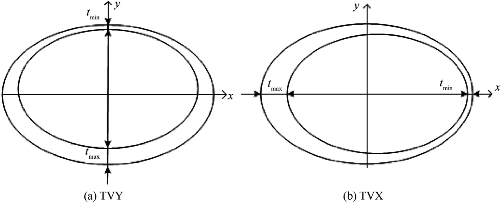
Fig.6.The different combinations of the ovality and the thickness variation.
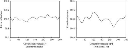
Fig.7.The measured radius of the shell.

Fig.8.The results of ultrasonic scanning.
The experimental test above was used to validate the present FE method.With consideration of the effects of geometric imperfections, the measured thickness were used for the establishment of the FE model.The buckling mode in Fig.14 shows that the deformations near the 270are larger than other regions, it may attribute to the variation of shell thickness.The predicted buckling pressure is 9.78 MPa, which can be located from the equilibrium path.The relative error between the FE model and experimental value is 6.5%, this shows the accuracy of the present method.
3.2.Buckling shape
The buckling shapes of the shell with different combinations of ovality and thickness variation were studied,some typical buckling shapes at cross section in the middle length are listed in Fig.15.The buckling shape corresponds to the perfect shell(Δ=0 and ω=0)is also illustrated in Fig.15 (a) for comparison.The typical buckling shape of the shell only with TVX(Δ=0 and ω=20%)is illustrated in Fig.15(b),it can be seen that this buckling shape is quite different from the perfect shell, the right side of the shell moves inward while the left side hardly seems to move.Similarly, the typical buckling shape of the shell only with TVY (Δ = 0 and ω = 20%) is illustrated in Fig.15(c),it can be seen that the top of the shell moves inward while the bottom hardly seems to move.It can be concluded that when the shell under hydrostatic pressure,it tends to become dimpled due to the existence of thickness variation.The typical buckling shape of the shell only with ovality(Δ=1%and ω=0)is illustrated in Fig.15 (d), which is also quite different from the perfect shell,it can be seen that the shell tends to become flat due to the existence of ovality.Considering the interaction between the thickness variation and ovality, the typical buckling shape corresponds to the shell with both ovality and TVX(Δ=1%and ω=20%)is illustrated in Fig.15(e).Compared with Fig.15(b),it can be seen the major difference is that the dimpled regions at the right side change to bulging deformation,which is due to the introduction of the ovality.For comparison,the typical buckling shape of the shell with ovality and TVY (Δ = 1%and ω = 20%) is illustrated in Fig.15(f), it can be seen that the dimpled regions in Fig.15 (c) becomes flatter when the ovality is introduced.In summary, the buckling shape for the composite cylinder shell with geometric imperfections is determined by the thickness variation and ovality together.
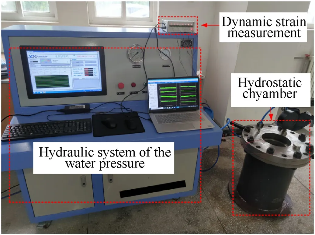
Fig.9.The hydrostatic pressure equipment.
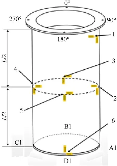
Fig.10.The location of the strain gauges.
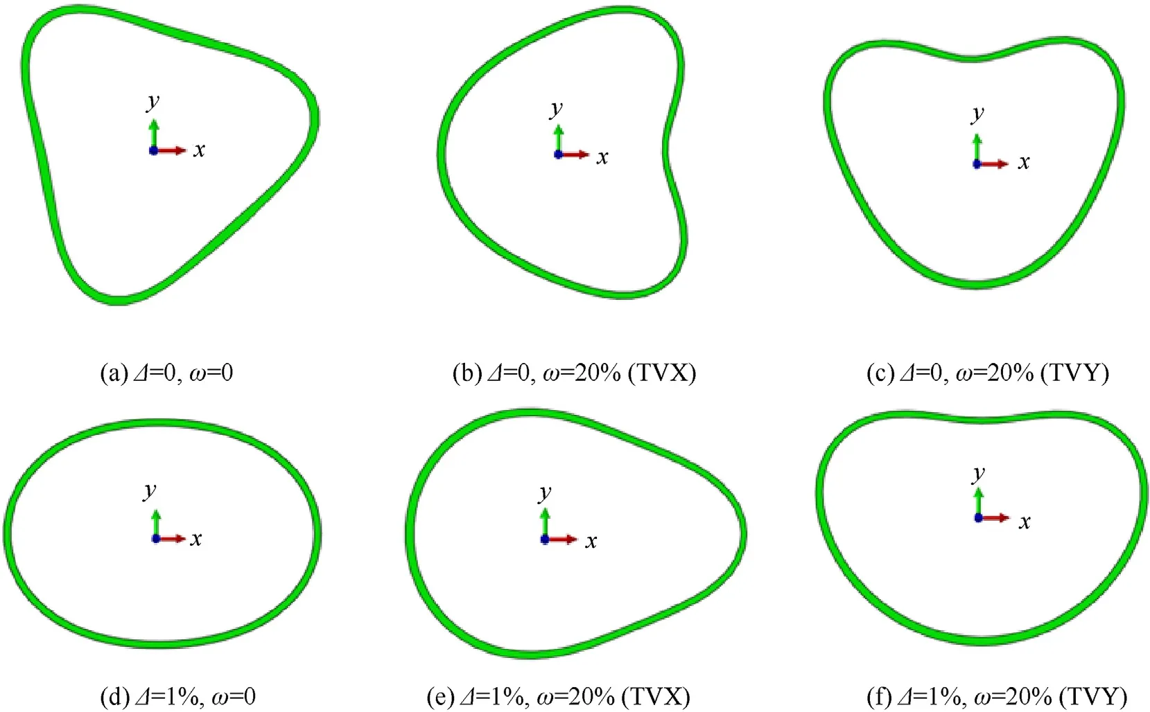
Fig.15.The typical cross-sectional buckling shape of the cylinder shell in middle length.
3.3.Buckling pressure
The buckling pressures of the composite cylinder shells with ovality and thickness variation are listed in Table 4.Fig.16 shows the relationship curves of buckling pressure and ovality under different TVY, it can be seen that when the ovality is higher than 0.1%, the buckling pressure decreases with the increase of ovality.However, the changing trends are different when the ovality is lower than 0.1%, especially for the curve of the shell without thickness variation(ω=0),the buckling pressure increases a little rather than decreases with the increase of ovality.The reason for this unusual phenomena is that when a small ovality is introduced,the shell starts to deform along with different shape compared with the perfect cylinder.As shown in Fig.17, the buckling shapes are different due to the introduction of ovality, which leads to the difference in buckling pressure.A similar conclusion was also obtained by Petreli [15].

Table 4 Buckling pressure for the imperfect composite cylinder shells (Unit:MPa).
Fig.18 presents the relationship curves between the buckling pressure and the TVY under different ovalities, it shows that the buckling pressure decreases with the increase of thickness variation.When the thickness variation increases from 0 to 40%, the buckling pressure drops 4.4 MPa when ovality equals to 0.1%,while it drops 3.61 MPa when ovality equals to 1%,so the influence of the ovality on buckling pressure gradually decrease with the increase of thickness variation.When ω=0,the change of buckling pressure is 1.08 MPa when the ovality increases from 0.5%to 1%,so the change rate of buckling pressure with respect to ovality is-216.00.For the curve of Δ=0.5%,the change of buckling pressure is 1.21 MPa when the thickness variation increases from 0 to 20%,the change rate of buckling pressure with respect to thickness variation is -6.05.Through comparison, it is clear that the ovality has greater influence on buckling pressure than the thickness variation.
The effects of the TVX and TVY on buckling pressure are also discussed in this paper.The dashed lines in Fig.19 present the relationship curves between the buckling pressure and the ovality under different TVX, the solid lines represent TVY are also plotted in Fig.19 for comparison.It can be seen that the buckling pressures of the TVY shells are all lower than the TVX shells.Therefore, the TVY can be considered as the worst case when considering the thickness variation.This conclusion also can be drawn from the relationship curves of buckling pressure versus TVX and TVY under different ovalities (see Fig.20).
3.4.Proposed design formula
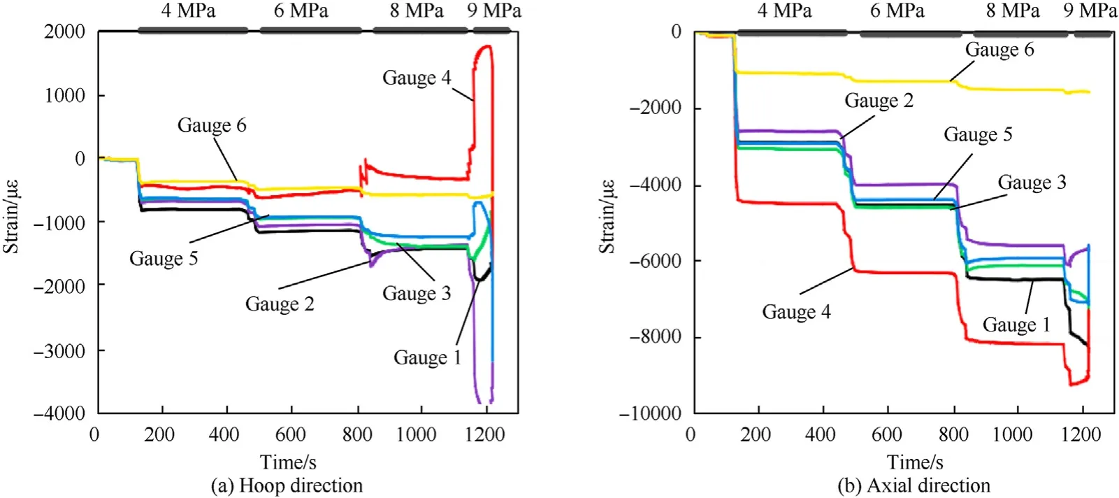
Fig.11.The strain responses for each strain gauge.
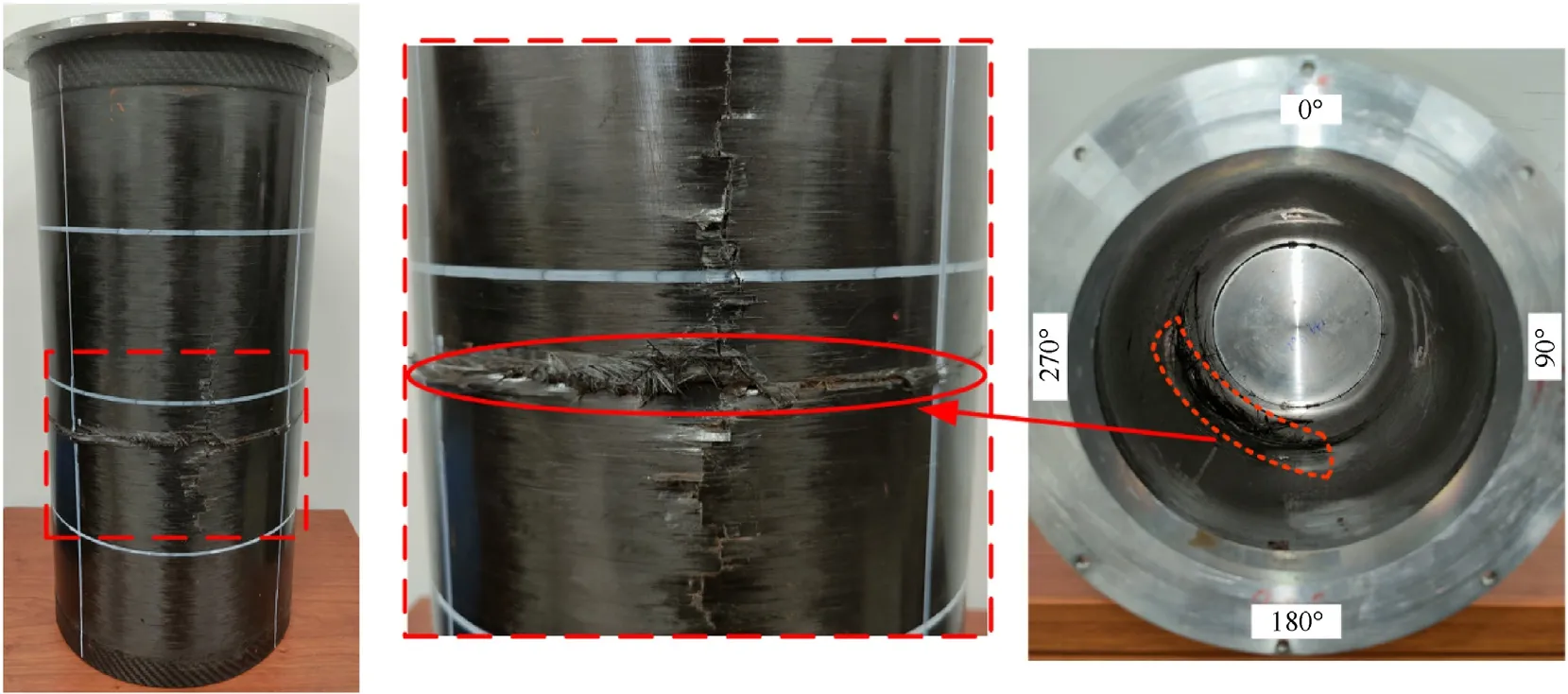
Fig.12.The failure of the CFRP composite cylinder.
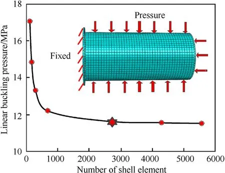
Fig.13.The convergence result of mesh size and boundary condition.
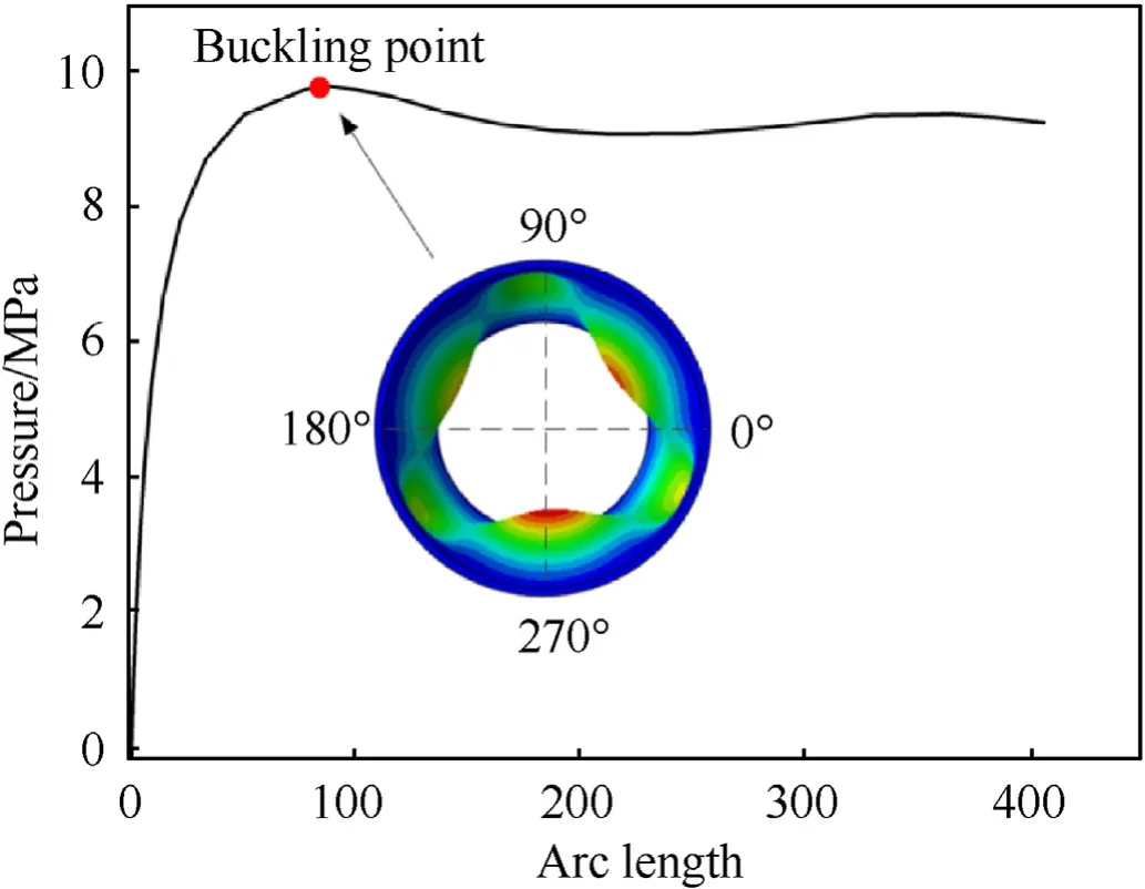
Fig.14.The equilibrium path of the shell(Deformations are magnified by a factor of 5).
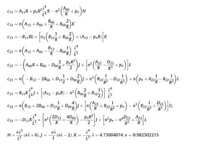
An analytical formula to calculate the linear buckling pressure of composite cylinders under hydrostatic pressure was proposed by Chun [31], in which the equilibrium equations consider the perturbed state [32].The displacements of the deformed shell are approximately by the beam function and the buckling problem is solved using the Galerkin method [33].The simplified form of calculating the eigenvalue problem is as following:
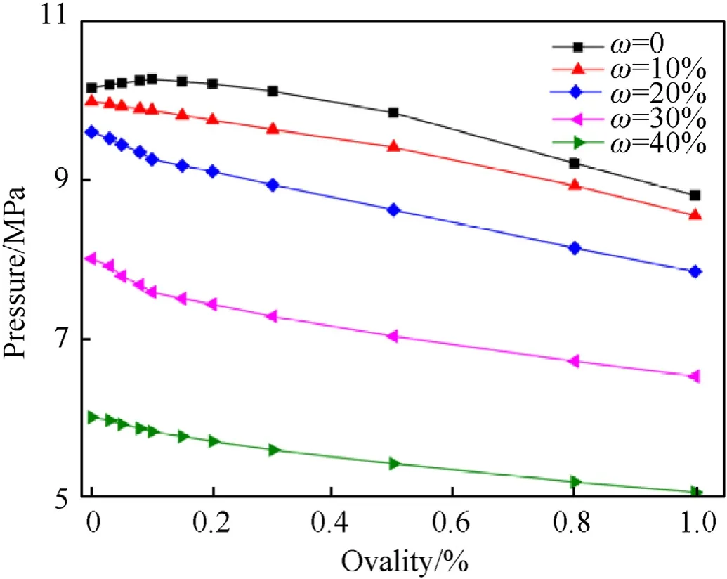
Fig.16.Buckling pressure versus ovality under different TVY.

where the variableis the number of hoop half waves of the buckling mode,and the corresponding buckling pressure is.The cterms are detailed in Apendix A.The critical buckling pressureis the lowestvalue which satisfies Eq.(7).
By analyzing the buckling pressures above,it is obvious that the buckling pressure is a function of the ovality and the thickness variation.The buckling pressure()of the composite shell with ovality and TVY is firstly normalized by the buckling pressure()of the shell only with the ovality.As the curves in Fig.21,it can be found that the relationship between the thickness variation and the normalized buckling pressure can be described by a power function model[21].So the expression of the normalized buckling pressure is as follows:
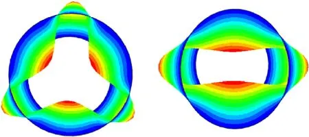
Fig.17.The deformed shapes of shell without (left) and with (right) ovality.
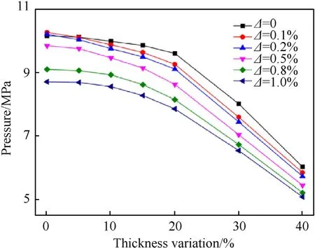
Fig.18.Buckling pressure versus TVY under different ovalities.
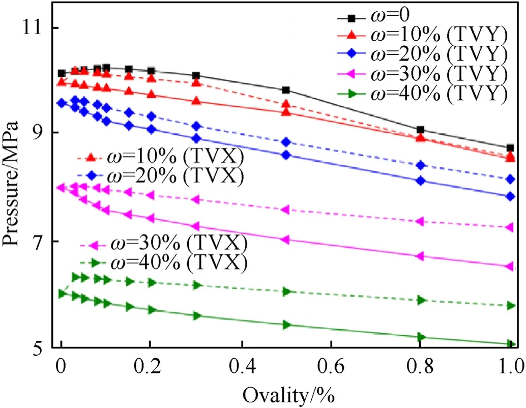
Fig.19.Buckling pressure versus ovality under different TVX (dashed line) and TVY.
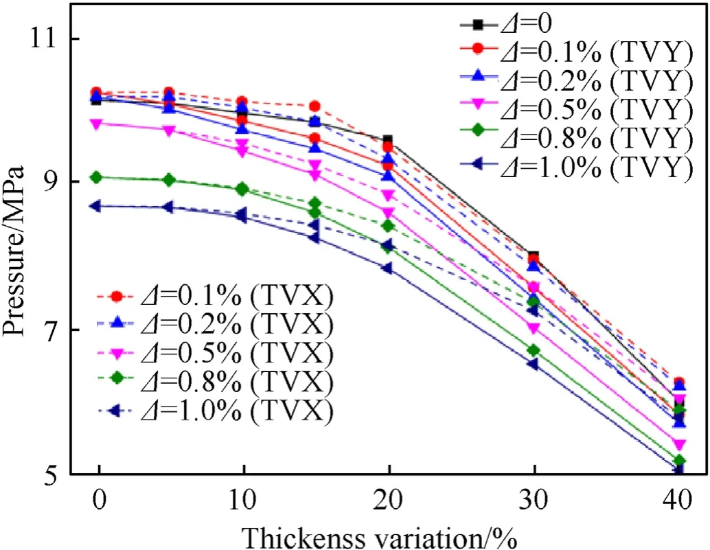
Fig.20.Buckling pressure versus TVX(dashed line)and TVY under different ovalities.

There have been some literature on the buckling of oval cylindrical shells [28,29].As the range of the ovality is only 0-1%, the cylindrical shells with ovality studied in this paper are considered as imperfect circular cylindrical shells.The buckling pressure of a composite shell with ovality () is normalized by the linear buckling pressure () of the perfect composite shell.As shown in Fig.22, the normalized buckling pressure goes linearly down with the ovality.The relationship curves of normalized buckling pressure of shells with TVY in Fig.22 also demonstrate this relationship.Therefore, whether the thickness variation is considered or not, the buckling pressure of the composite shell with ovality(is correlated positively with the linear buckling pressure.Based on the formula above,the buckling pressure of the composite shell with ovality and thickness variation () can be finally determined by the following expression:

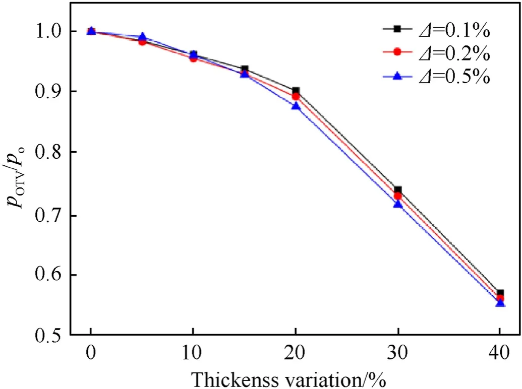
Fig.21.Normalized buckling pressure versus thickness variation curves with different ovalities.
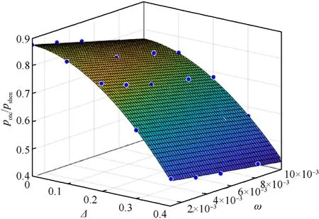
Fig.23.Results of multiple regression analysis.
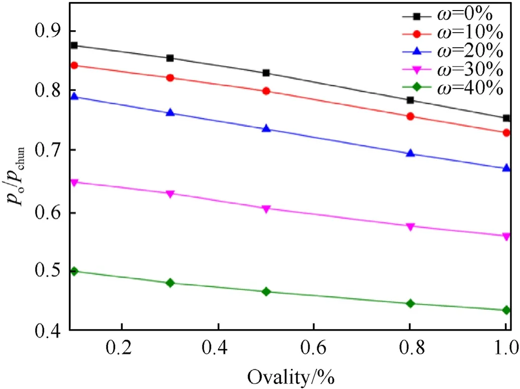
Fig.22.Normalized buckling pressure versus ovalities curves with different TVY.
The nonlinear regression method is used to determine the unknown coefficients here.As the fitting plot shown in Fig.23, the correlation coefficient of the fitting curve surface is 99.52% by multiple regression analysis.The values of the unknown coefficients are obtained:= -2.409,= 1.859, c = -13.622,d = 0.8938.Therefore, the buckling pressure of a composite cylinder shell with arbitrary combinations of ovality and thickness variation can be calculated by the following formula:

4.The validation of the proposed formula
The proposed formula was compared with the FE method for the present composite cylinder with different layup conditions.The buckling pressures calculated by the proposed formula,, and FEA,,for the cylinder with[90(±θ)90]are listed in Table 5.The error within the range of -5.8%~4.4% under different combinations of ovality and thickness variation.

Table 5 Predicted buckling pressure obtained by the formula compared and FEA.
As the geometrical imperfections sensitivity depends significantly on slenderness of the shell, the formula calculations of the shell with different geometrical dimensions were also compared with those obtained from FEA.Fig.24 shows the comparison results of shells with different radii, it can be seen that the errors are comparatively large when the radius to thickness ratios are small,it is because the relatively thicker the shell thickness, the less sensitive to the geometric imperfections.Fig.25 shows the comparison results of shells with different lengths, it can be seen that the buckling pressures calculated from the proposed formula are basically consistent with the FE results.All the errors are less than 15%.,so these general cases indicate that the proposed formula has good applicability in evaluating and predicting buckling pressure of composite shells with such geometric imperfections.
Although the proposed formula can be used to predict the buckling pressure of the composite cylinders with reasonable accuracy, the information about the geometrical imperfection is required.However, obtaining this information for real large scale structures is very costly or even impossible at design stage.It is a real practical restriction of using the suggested formula.From Figs.24 and 25,it can be seen that the buckling pressures calculated from the proposed formula are basically lower than the FE model.It means that the prediction of the proposed formula is more conservative.Therefore, according to processing accuracy of the structure,the lower bound estimation of buckling pressure can also be obtained effectively without measuring these imperfections.Despite there is a certain error, it is economic.
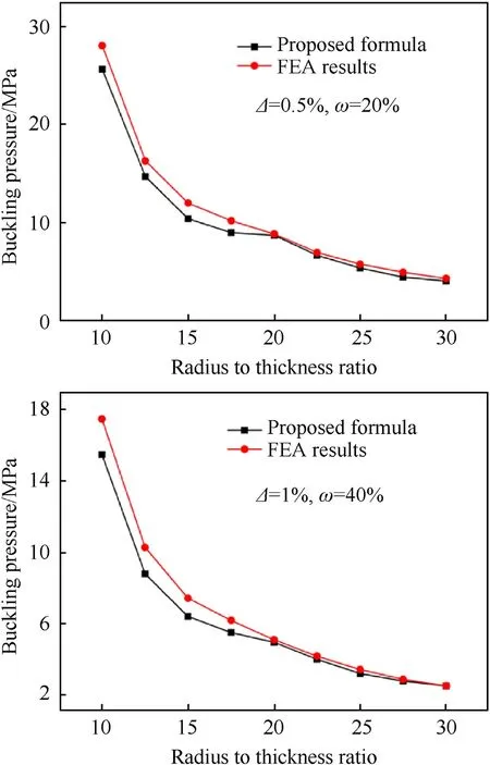
Fig.24.Results of shells with different ratios of radius to thickness.
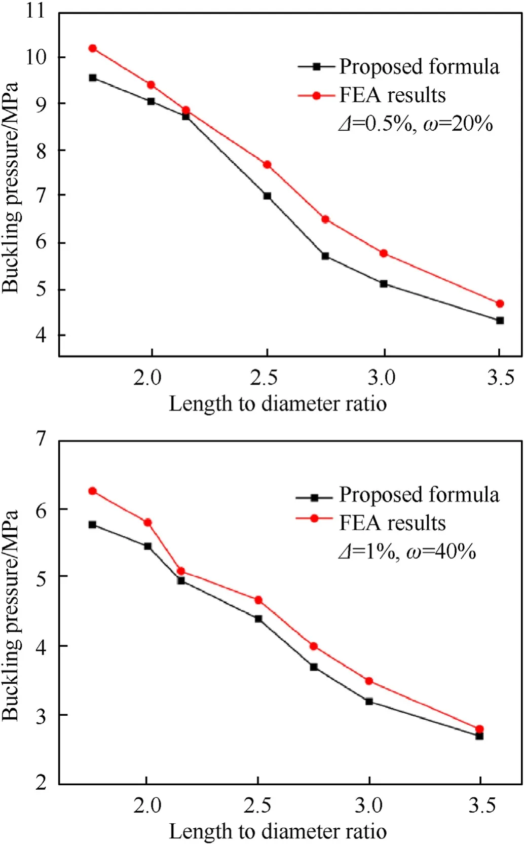
Fig.25.Results of shells with different ratios of length to diameter.
5.Conclusion
This paper focuses on the buckling behaviors of the CFRP composite cylindrical shells with ovality and thickness variation.A composite cylinder was manufactured and tested, and the numerical analyses were conducted by using the finite element method.The main conclusions are as follows:
(1) From the measured data during the experiment, it can be seen that the deformations near the free end of the shell are relatively small, and the postbuckling behaviour of the composite shell is hard to be observed.
(2) The final buckling shape of the composite cylinder shell under hydrostatic pressure is determined by two factors,where the ovality is to make the shell flat and the thickness variation is to make the shell dimpled.
(3) The rules of influence of ovality and thickness variation on the buckling pressure are presented by data analysis.By comparison, the ovality has greater influence on buckling pressure than the thickness variation.
(4) A formula is proposed to predict the buckling pressure of the
The authors declare that they have no known competing financial interests or personal relationships that could have appeared to influence the work reported in this paper.
This work is supported by the National Natural Science Foundation of China (Grant No.51909219), the National Key Research and Development Program of China (Grant No.2016YFC0301300),Fundamental Research Funds for the Central Universities (Grant No.3102019JC006), and China Postdoctoral Science Foundation(Grand No.2020M673492).
composite shells,and the accuracy of the formula is verified.Especially for the structure which is hard to be measured,the proposed formula provides a more convenient way to calculate the lower bound estimation of buckling pressure,which is very economic.
According to the reference [31],is the middle radius of the cylinder shell,is the total shell length.The, Band Dare the membrane, coupling and bending stiffness related to the material properties [34].
- Defence Technology的其它文章
- Defence Technology
- Roll angular rate extraction based on modified spline-kernelled chirplet transform
- Preparation of the core-shell HMX@CS microparticles by biological excitation:Excellent hydrophobic-oleophilic properties and decreased impact sensitivity effectively
- Quantitative prediction and ranking of the shock sensitivity of explosives via reactive molecular dynamics simulations
- An efficient light-to-heat conversion coupling photothermal effect and exothermic chemical reaction in Au NRs/V2C MXene membranes for high-performance laser ignition
- Hygrothermal effect on high-velocity impact resistance of woven composites

