Design of the stripping unit and the electromagnetic analysis unit for the E//B NPA on HL-2A/2M tokamak
Linge ZANG (臧臨閣),Yufan QU (屈玉凡),Yuan LUO (羅圓) and Weiping LIN (林煒平)
1 Southwestern Institute of Physics,Chengdu 610218,People’s Republic of China
2 Key Laboratory of Radiation Physics and Technology of the Ministry of Education,Institute of Nuclear Science and Technology,Sichuan University,Chengdu 610064,People’s Republic of China
Abstract An E//B neutral particle analyzer is under development for fast ion diagnosis on HL-2A/2 M tokamak.The stripping unit is composed of a stripping room (equipped with two differential tubes and a gas supply bellows),a vacuum chamber and a vacuum pumping system.The stripping efficiency of the stripping room is calculated in the form of global efficiency R×f+1,where R is the non-scattered-away rate and f+1 is the fraction of charge state +1.The magnetic field of the E//B analyzer is produced with a permanent magnet.The yoke and the poles of the magnet are made of mild steel and the magnet plates are made of NdFeB.The magnetic poles are specially designed to focus the ion trajectories and to increase the use rate of the magnet.The shape of the magnet and the electric plates are carefully designed so that the ions are dispersed into two lines of H+and D+on the detector plane.For each line,the energy increases from 10 to 200 keV from one side to another.
Keywords: fast ion,stripping room,particle trajectory,neutral particle analysis
1.Introduction
A neutral particle analyzer (NPA) detects the atoms of hydrogen isotopes escaping from the plasma.In a hightemperature plasma like ITER,the escaping atoms are produced in three main neutralization processes: (1) charge exchange with the background hydrogen isotope neutrals;(2)radiative recombination of the protons (deuterons,tritons)with the electrons; (3) electron capture from (or charge exchange with) the hydrogen-like impurity ions.Figure 6 in[1] shows the neutralization rate of the thermal D+and T+ions versus energy for different reactions.Process (1) is only dominant in the energy range of 20-50 keV.Beyond 50 keV,processes (2) and (3) play significant roles in the neutralization.At 200 keV the neutralization rate of the electron captured from He+and the radiative recombination is almost one order higher than the charge exchange with D0and T0.The cross-sections for the charge-exchange reactions of fast triton in a higher energy range are shown in figure 5 of[2].An E//B NPA has both energy and mass resolutions.In an LHD device,it measures the flux of fast neutrals with different energies[3],enhancing the understanding of fast ion behavior[4].In the future device like ITER,E//B NPA will be applied to measure the D/T fuel ratio [5].The high-energy particle fluxes of D and H are measured on JET tokamak during ICRF heating experiment with an E//B NPA[6].The density ratio of D and H are measured on LHD with an E//B NPA [7].The NPA counting rate is simulated for D and T on ITER [5].
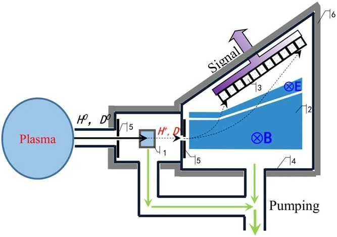
Figure 1.Schematic diagram of the E//B NPA designed for HL-2A/2 M tokamak.1-stripping room,2-analysis unit,3-detector array,4-vacuum vessel,5-collimating diaphragm,6-shielding shell.
There are many E//B NPAs built around the world.The E//B NPA designed by Medley [8] realizes mass and energy resolutions with a superimposed electromagnetic field.It measures hydrogen,deuterium and tritium.The energy range is 0.5≤A(amu)E(keV)≤600,where amu is the atom mass unit.The key components include a gas stripping cell,an electric magnet and microchannel plate (MCP) detectors.A compact NPA (CNPA) [9] analyzes the masses and energies with a tandem electromagnetic field.It could measure hydrogen of 0.8-80 keV and deuterium of 0.66-36 keV.The key components include a thin diamond-like foil,a permanent magnet and channel electron multipliers (CEM).
A tandem type E//B NPA is under development for the fast ion measurement on HL-2A/2 M tokamak.This article discusses the design of the analyzer,similar to that described in [9,10].The analyzer parameters are matched to the conditions of its use on the HL-2A/2 M tokamak and the purpose of fast ion measurement.This NPA is capable of H and D resolution,and the energy range is set to 10-200 keV for both H and D.The beam injector on HL-2A could inject D of 30-50 keV.The beam injector(positive source)on HL-2M could inject D up to 80 keV and H up to 50 keV.A negative-ionsource neutral beam is underdeveloped,the upper limit of the energy range for which is 200 keV for both D and H.However,the current plan is that only positive source beams will be installed on HL-2M.The upper limit of the energy range for this NPA is set to 200 keV because in the previous plan the negative-ion-source neutral beam will be installed on HL-2M.The lower limit is set to 10 keV because this NPA is built for fast ion diagnosis instead of ion temperature measurement.As a contrast,the energy range of CNPA in[9]is 0.8-80 keV for hydrogen and 0.8-40 keV for deuterium,and the energy range of CNPA in [10] is 64-968 eV.Both the CNPAs in[9,10] have covered the energy range for ion temperature measurement.As shown in figure 1,the NPA system in this work includes a gas stripping unit,an electromagnetic analysis unit and a two-dimensional detector array.An NPA can use either a gas stripping unit or a foil stripping unit to ionize fast neutrals.However,a foil could lose its thickness or even be damaged due to the bombardment of the fast particles in long time run.The NPA described in this paper uses a gas stripping unit to avoid the replacement of the stripping unit.The fast neutrals escaping from the plasma are stripped into ions in the stripping unit and then fly into the electromagnetic analysis unit.The ion trajectories are dispersed by the two fields and end on the detector plane at different positions according to their masses and energies.
In this paper,two pieces of work are introduced for the recent development of this NPA.First,the mechanical structure of the gas stripping unit has been designed and the dependency of the stripping efficiency on the gas pressure has been simulated.Second,the mechanical structure of the electromagnetic analysis unit has been designed and the particle trajectories have been simulated.
2.Design of the stripping unit
Figure 2(a)shows the mechanical design of the stripping unit and the dimensions are labeled in figure 2(b).The stripping unit is composed of a stripping room (equipped with two differential tubes and a gas supply bellows),a vacuum chamber(equipped with two collimating holes)and a vacuum pumping system [11].Stripping room 1 is the main position of gas storage and bellows 4 supplies H2to it.The pressure in the stripping unit depends on the diameter and length of the differential tube 2.The structure of the windowless stripping room 1 is carefully designed so as to keep a proper gas pressure.The overall pressure will be compatible with the tokamak vessel pressure.The front and rear tube 2 are the entrance of the neutral particles and the exit of the ions,respectively.Both the two differential tubes 2 are 36 mm long and the inner diameter is 4 mm.On the two sides of the vacuum chamber 3,two holes 6 mm in diameter labeled 7 and 8 are the entrance and exit of the particles,respectively.The neutrals enter the stripping room through entrance hole 7 and differential pipe 2,they are stripped into ions in stripping room 1 and flying into the analysis unit through differential pipe 2 and exit hole 8.Machinery bearing molecular pump is adopted for vacuum pumping to avoid the influence of a stray magnetic field.The molecular pump of 340 L s?1pumping speed is connected to the bottom of gate valve 11.
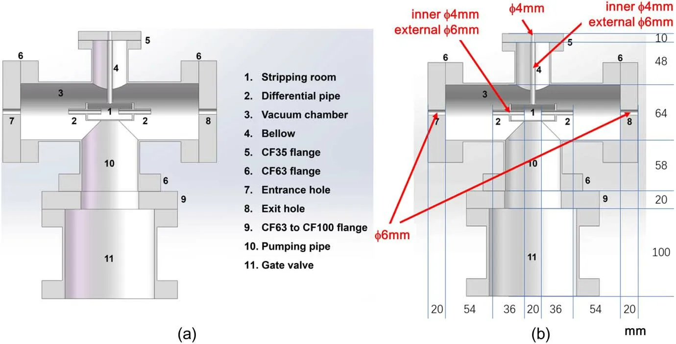
Figure 2.Design (a) and the dimensions (b) of the mechanical structure for the stripping unit.
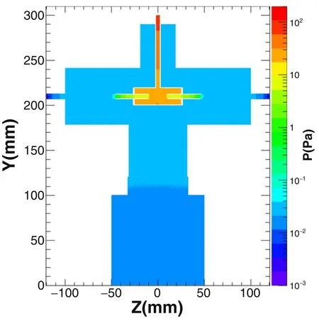
Figure 3.Simulation of the gas pressure in the stripping unit.P0=200 Pa.
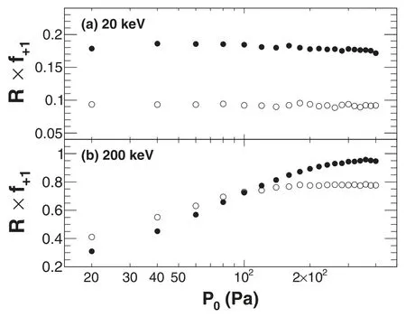
Figure 4.Global efficiency of R×f+1 as a function of the pressure P0 for the incident energy of E=20 keV (a) and 200 keV (b).Solid and open circles represent for H and D,respectively.
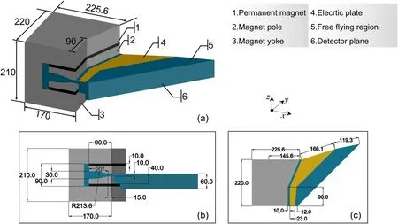
Figure 5.Design of the permanent magnet.(a)A bird view,(b)top view,(c)side view.The directions of x,y,z axes are labeled in the figures.
The gas pressure profile in the vacuum chamber has been simulated with ANSYS Fluent and MolFlow+ [12].The result is shown in figure 3.At the bottom side and the left side of the figure there are plotting scales to check the exact geometry.The gas pressure at the top of the supply bellows 4 is set to be P0.If P0=200 Pa,the gas pressure inside the stripping room is about 20-30 Pa.
Based on the gas pressure distribution in figure 3,the stripping efficiency of the stripping room is studied using GEANT4 [13,14].The following four processes were taken into account in the simulation (1).The stripping efficiency of the stripping room,say,the ratio of H+number at the output differential tube and H0number at the input differential tube,is calculated in the form of combined global efficiency R×f+1.Here,R is the transmission rate and f+1is the fraction of charge state +1.Both R and f+1are studied with the Monte Carlo method.Because the diameters of the two differential pipes are smaller than those of the entrance and exit holes,some of the incident particles will be stopped by the geometry of the stripping chamber.Moreover,owing to the Coulomb scattering of the incident particles and the target atoms (between the nuclei),some of the incident particles are scattered away from their original directions.The transmission rate R is defined as the ratio between the number of particles reached at the exit hole 8 after passing through the stripping chamber with H2gas (P0>0 Pa) and that without the gas (P0=0 Pa,vacuum).Thus,the particle loss induced by the geometry of the stripping chamber was canceled out.f+1is calculated by tracing the charge state of each particle with the Monte Carlo method based on the cross-sections of the four charge exchange processes.It is defined as the ratio between the number of particles with charge state +1 and charge states 0,+1 and ?1 reaching the exit hole 8.100,000 events are traced for each condition.The formerly published paper[11]has given a lot of further details for the calculation of both R and f+1.
Figures 4(a)and(b)show the dependencies of R×f+1on P0for E=20 keV and E=200 keV,respectively.Here,E is the energy of the incident atoms.We could see that,when E=20 keV,R × f+1is almost flat in the studied pressure range,keeping its value at about 0.16,except for a small drop in the high-pressure region (200-400 Pa).The reason is explained as follows.Both the cross-sections of H→H++e?and H++e?→H are so high at 20 keV(see figure 5 of[11])that even at 20 Pa the reaction is saturated for these two reactions.The cross-section of H+e?→H?is much lower so that processes (3) and (4) could be neglected.As a result the value of f+1is approximately σ0,1/(σ0,1+σ1,0)where σ0,1and σ1,0are the cross-sections of H→H++e?and H++e?→H,respectively.The drop at 200-400 Pa is mainly because R drops due to more Coulomb scatterings in denser particles.When E=200 keV,R×f+1is low when P0is small,and goes higher when P0goes higher.At P0=200-400 Pa,R×f+1is up to 0.95.The reason is explained as below.The cross-section of H→H++e?is low so that the reaction is not saturated at 20 Pa.Most of the atoms reaching exit hole 8 are just the original H passing the stripping chamber and free from any reaction,so R × f+1is low when P0is small.When the pressure goes higher,the reaction fraction is getting higher until saturated.The cross-section of H++e?→H is much smaller than H→H++e?at 200 keV so f+1is close to unity.The results for D could be explained in a similar way but it should be noticed that with the same energy,the velocity of D is 1of that of H,so the cross-section is different,thus the curves in figure 4 are different.
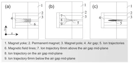
Figure 6.(a) Magnet field in the magnetic gap,(b) focusing effect of the ion trajectories when the ions shoot into the magnetic gap from different incident positions with respect to the mid-plane,(c)focusing effect of the ion trajectories when the ions shoot into the magnetic gap at different incident angles.
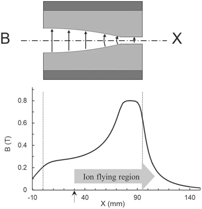
Figure 7.Profile of the magnetic field strength B in Tesla along x direction.The ions shoot into the magnetic gap at x=30 mm,labeled with an arrow under the x axis.The ion flying region is labeled with a thick arrow parallel to the x axis.
3.Design of the analysis unit
The design of the ideal electromagnetic fields for an E//B NPA has been presented in a former paper [15].However,there is no 2D magnetic focusing of the scattered ions and the electrostatic deflector has a simplified shape in this preliminary work.The design of the mechanical structure of the analysis unit in this work follows the idea (the shape of the magnet gap to focus the scattered ions and the shape of the electrostatic deflector to arrange the striking point on the detector plane) first presented in [9].The magnetic field is produced with a permanent magnet.This permanent magnet is composed of a magnet yoke (made of soft magnetic steel),two magnet poles (made of mild steel) and two NdFeB magnet plates,as shown in figure 5.The NdFeB magnet plates are placed in between the yoke and the poles.The remanence of the NdFeB magnet is Br=1.2 T.The two electric plates are made of polished oxygen-free copper and the space between the two plates is 1.2 cm.
The magnetic poles are specially designed.As shown in figure 6(a),the magnetic field lines are a little bit curved at the inner side of the magnetic gap.When the ions shoot into the magnetic gap from different positions with respect to the midplane,their trajectories are focused by the curved field line towards the mid-plane,as shown in figure 6(b).In figure 6(c),when the ions shoot into the magnetic gap at different angles with respect to the mid-plane,their trajectories are focused parallel to the mid-plane.Therefore,this design could focus the ions towards and parallel to the mid-plane of the magnetic gap,thus preventing the ions from striking the magnet poles,increasing the rate of ion transmission.
Another benefit of this design is to increase the use ratio of the magnet.As shown in figures 7 and 8(a),the magnetic field strength is much lower at the ion entrance than that at the ion exit,thus the ions fly over the most intense part of the magnetic field.At the weakest field side (inner side of the magnetic gap),there are no ion trajectories.If the poles are designed to be flat so that the profile of B is flat,the magnetic field strength between x=0 and x=30 mm is kind of‘wasted’because there is no ion flying over this region.In this sense,the use ratio of magnet material is increased with this design.Both the magnetic field shown hereinbefore and the particle trajectories shown in the paragraph below are simulated using the multi-physics software COMSOL.
As shown in figures 8(b)and 9,on the detector plane,the striking points of the ions are clearly divided into two lines.The top line is H+and the bottom line is D+.As shown in figure 9,the separation between the two lines is about 1.8 cm,enough for putting the detectors.For each line,from the left to the right,ion energies increase from 10 to 200 keV.
Figure 10 shows the ion trajectories and striking points on the detector plane when the incident angle of the ions is scattered.The ions are emitted from an identical point but the incident angle is scattered in a 3° cone.Due to the focusing effect,the ion trajectories are bent parallel to the mid-plane of the magnetic gap.The striking points of an identical energy are localized in a small spot comparable to the area of the detector (6 mm×6 mm).This demonstrates that this special design does have a focusing effect on the ions with scattered incident angles.

Figure 8.Simulation result with COMSOL.(a)The magnetic field strength and ion trajectories in the analysis unit,(b)the ion striking points on the detector plane.
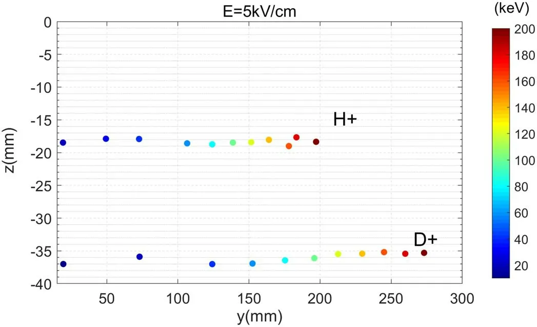
Figure 9.The ion striking points on the detector plane in y-z coordinate.

Figure 10.The ion trajectories and striking points on the detector plane when the incident ions are scattered in a 3° cone.
4.Discussion
The energy resolution has not yet been studied for this E//B NPA.The area of the detector (6 mm×6 mm) would be a very important factor for the energy resolution.The energy resolution could then be studied with COMSOL software as future work.
The magnetic field is determined by the maximum field of the commercial permanent magnet product we could purchase.The size of the NPA is mainly determined by the size of the magnet.The size of the magnet is determined by the energy range of NPA and its field strength.To reduce the size of NPA for a fixed energy range we need to select a magnet with a stronger field.
One of the most important goals of this NPA is to study the interaction between MHD instabilities and fast ions.This physics target requires that the time resolution of the energy spectrum should reach 1 ms so that the effects of fast chirping and bursting modes could be studied.The upper limit of the counting rate for a single detector is 5×10⁵s?1,set by the hardware of the detector unit.The time resolution of the energy spectrum is further determined by the incident-neutral flux.For the most ideal case,for example,if the counting rate for each detector is 5×10⁵s?1and the time resolution is set to 1 ms,the energy spectrum will be plotted with 500 counts on each channel.The fast neutral flux for a general NPA device has been studied with the most fundamental equations in [16],including the solid angle effect based on the plasma parameters in a synthetic beam heated HL-2M discharge from TRANSP.The neutral flux with an energy of 20-80 keV is(3.6-10.5)×106s?1for a φ=4 mm NPA entrance window.There are four factors to determine the corresponding count rate at each detector.(1)The total incident particle flux.Since the inner diameter of differential pipe 2 is 4 mm,so the total incident particle flux into the stripping room is (3.6-10.5) ×106s?1.(2)The stripping efficiency.As shown in figure 4,if we fix P0to 200 Pa,the stripping efficiency depends on the particle energy.The stripping efficiency for 20 keV D is about 0.08,and for 200 keV D is about 0.75.Here we assumed the stripping efficiency to be 0.2 for 20-80 keV.(3) The transmission rate of the ions through the analysis unit and the free-flying region until the detectors.In a vacuum level of 5×10?4Pa and at room temperature,the mean free path of a 20 keV H+is about 45 m.The flying path through the analysis unit and the free-flying region is no longer than 1 m,so the H+is nearly collision free with the background molecules.For the same reason,D+is also nearly collision free with the background molecules.Therefore,the transmission rate is assumed to be 1 for both H+and D+.(4) The detector size.The area of the detector is 6 mm×6 mm.There are 16 detectors for 20-200 keV and about 6 detectors for 20-80 keV.On the detector plane in figure 9,the distance between 20 and 200 keV striking point is about 260 mm for D+.Considering the four factors above,the count rate for each detector is: (3.6-10.5)×106s?1×0.2×1×6×16/260/6=(4.4-12.9)×104s?1.If the time resolution is set to be 1 ms,the energy spectrum will be plotted with 44-129 counts on each channel.Since the energy range is 20-200 keV and the number of the detectors for each mass channel is 16,the averaged energy interval is (200?20)/(16?1) = 12 keV.
In this simulation work,the ions start from the very entrance of the magnet.However,the ions are actually born in the stripping unit,so the start point should be inside stripping room 1.Then the trajectories will be different from in this work.
5.Summary
An E//B NPA capable of energy and mass resolution is under development for HL-2A/2 M tokamak.The design of the analyzer is similar to the CNPA on the SSPX spheromak,and the parameters are matched to the conditions of its use on the HL-2A/2 M tokamak.The mechanical design and the simulation results for the stripping unit and the analysis unit are introduced in the paper.For the stripping unit,the global efficiency is highest at P0=20-50 Pa when the energy of the incident ions is E=20 keV and P0=200-400 Pa for E=200 keV.For the analysis unit,the magnet is specially designed so that the magnetic field could focus the ion trajectories towards the mid-plane and the use ratio of the magnet is increased.The preliminarily designed analysis unit could realize mass and energy resolution with the positions on the detector plane.The goals of this design are to study the interaction of the MHD instabilities and the fast ions.The present design could reach a time resolution of 1 ms and an energy interval of 12 keV.
Acknowledgments
This work is supported by the National Magnetic Confinement Fusion Energy R&D Program of China(Nos.2018YFE0310200 and 2019YFE03020003) and Sichuan Science and Technology Program (No.2019YFH0128).
 Plasma Science and Technology2022年6期
- Plasma Science and Technology的其它文章
- Recent progress on the J-TEXT three-wave polarimeter-interferometer
- Space-resolved vacuum-ultraviolet spectroscopy for measuring impurity emission from divertor region of EAST tokamak
- Development of a combined interferometer using millimeter wave solid state source and a far infrared laser on ENN’s XuanLong-50(EXL-50)
- Bench test of interferometer measurement for the Keda Reconnection eXperiment device (KRX)
- Neutron yield measurement system of HL-2A tokamak
- Study of the fast electron behavior in electron cyclotron current driven plasma on J-TEXT
