Elastoplastic behavior of frozen sand–concrete interfaces under cyclic shear loading
Jian CHANG, Jian-kun LIU,2,3, Ya-li LI, Qi WANG, Zhong-hua HAO
Research Article
Elastoplastic behavior of frozen sand–concrete interfaces under cyclic shear loading
Jian CHANG1, Jian-kun LIU, Ya-li LI1, Qi WANG1, Zhong-hua HAO1
1School of Civil Engineering, Beijing Jiaotong University, Beijing 100044, China2School of Civil Engineering, Sun Yat-sen University, Zhuhai 519082, China3Southern Marine Science and Engineering Guangdong Laboratory (Zhuhai), Zhuhai 519082, China
The resilient modulus, accumulated plastic strain, peak shear stress, and critical shear stress are the elastoplastic behaviors of frozen sand–concrete interfaces under cyclic shear loading. They reflect the bearing capacity of buildings (e.g. high-speed railways) in both seasonal frozen and permafrost regions. This study describes a series of direct shear experiments conducted on frozen sand–concrete interfaces. The results indicated that the elastoplastic behaviors of frozen sand–concrete interfaces, including the resilient modulus, accumulated plastic strain, and shear strength, are influenced by the boundary conditions (constant normal loading and constant normal height), initial normal stress, negative temperature, and cyclic-loading amplitude. The resilient modulus was significantly correlated with the initial normal stress and negative temperature, but not with the cyclic-loading amplitude and loading cycles. The accumulated plastic shear strain increased when the initial normal stress and cyclic-loading amplitude increased and the temperature decreased. Moreover, the accumulated plastic shear strain increment decreased when the loading cycles increased. The accumulated direction also varied with changes in the initial normal stress, negative temperature, and cyclic-loading amplitude. The peak shear stress of the frozen sand–concrete interface was affected by the initial normal stress, negative temperature, cyclic-loading amplitude, and boundary conditions. Nevertheless, a correlation was observed between the critical shear stress and the initial normal stress and boundary conditions. The peak shear stress was higher, and the critical shear stress was lower under the constant normal height boundary condition. Based on the results, it appears that the properties of frozen sand–concrete interfaces, including plastic deformation properties and stress strength properties, are influenced by cyclic shear stress. These results provide valuable information for the investigation of constitutive models of frozen soil–structure interfaces.
Frozen sand–concrete interface; Cyclic direct shear test; Elastoplastic behavior; Direction of accumulated plastic strain; Boundary condition
1 Introduction
The behavior of the soil–structure interface significantly affects geotechnical engineering applications such as building foundations, tunnels, and pipelines. An increasing number of major engineering projects in northeast and northwest China, as represented by high-speed railways and La-Ge 400-kV direct current transmission lines, have been completed with the development of economical construction processes. The foundations of these constructions in permafrost regions are subjected to several loading cycles and from accumulated plastic strain, which may reduce their serviceability and longevity. The soil–structure interface has been considered as a transfer zone, and its properties are crucial for the shear strength of foundations (Randolph, 2003; Jardine et al., 2005; Hanzawa et al., 2007; Aghakouchak et al., 2015). The long-term stability and service performance of structures under cyclic loads are primarily influenced by the properties of that interface. As a result of the accumulated plastic strain under cyclic loading, the shear strength of a soil–structure interface is very different from that under monotonic loading, as determined by field test studies in permafrost regions (Feng, 2009). A comprehensive study of the properties of frozen interfaces under cyclic loading, such as seismic, traffic, and machine vibration loads, is essential for structural design. Hence, investigating the elastoplastic behavior of frozen soil–structure interfaces under cyclic loading, and precisely calculating the bearing capacity and understanding the deformation characteristics of construction in permafrost regions are urgent issues.
Much research has been conducted on the deformation characteristics of unfrozen soil–structure interfaces. An automated interface testing apparatus that can apply a constant normal load (CNL), constant normal stiffness (CNS), and constant normal height (CNH) was designed (Fakharian, 1996). An interface model using the critical state soil mechanics concept according to the framework of generalised plasticity and bounding surface plasticity was proposed (Liu et al., 2006; Lashkari, 2012). An elastoplastic constitutive model for the state-dependent behavior of cohesionless soil was developed (Li and Dafalias, 2000). The constitutive rules of cyclic behavior of the interface between a structure and gravelly soil using macro- and micro-observation results of a series of large-scale tests were investigated (Zhang and Zhang, 2009). A comparison of interface testing results from two different shear directions (axial and torsional) was conducted, which developed an improved fundamental understanding of granular-continuum stress–strain behavior (Martinez et al., 2015). They also proposed fundamental micro-mechanical processes that could explain the differences in behavior between axial and torsional tests. A method for incorporating the effect of particle breakage in improving the capabilities of an elastoplastic constitutive simulation of the cyclic accumulative contraction in granular interface modeling was introduced (Saberi et al., 2018a). Thereafter, the model was adapted and applied to various problems.
These studies on mechanical behaviors and constitutive models were conducted with respect to unfrozen soil. Frozen soil is different from unfrozen soil in terms of its microstructural and mechanical properties (Lai et al., 2009b). When soil is frozen, its strength will increase many times and the stress–strain relationship is more complex and sensitive to temperature. The strength of frozen soil increases with increasing confining pressure, but decreases when the confining pressure exceeds a certain value. These differences in characteristics can be attributed to the presence of polycrystalline ice, air, unfrozen water, and organic matter (Style and Peppin, 2012). The deformation and strength properties of frozen silty clay under monotonic and cyclic triaxial loading were studied and a criterion of cyclic failure was proposed (Xu et al., 2020). The dynamic behaviors of frozen silty soils with different coarse-grained contents by the modified MTS-810 apparatus were investigated, and it was found that the resilient modulus increased and the damping ratio decreased as the loading cycles increased (Zhang et al., 2019). Zhou et al. (2020) reported that, based on the study of the strength and deformation of frozen loess, the stress path has a sensitive influence on rheology and stiffness. The mechanical properties of the frozen interface were different from those of the unfrozen interface, due to its unique static and dynamic properties. The property of strength was the most significant difference. When soil was frozen, its strength increased many times and the stress–strain relationship was more complex and sensitive to temperature. The strength of frozen soil increased with increasing confining pressure, but the strength decreased when the confining pressure exceeded a certain value. These differences in characteristics can be attributed to the presence of polycrystalline ice, air, unfrozen water, and organic matter. This finding implied that further investigation is needed on the behaviors of frozen interfaces (Ma et al., 1999; Ling et al., 2013).
The frozen soil–structure interface (hereinafter referred to as the frozen interface) is an extremely thin contact zone between the structure and the frozen soil and is the most important factor influencing the safety and stability of structures in permafrost regions. The plastic strain of the frozen interface accumulates under cyclic loading (e.g. seismic, wind, and traffic loads) and contributes to building failures. Experimental research was conducted on the behaviors of frozen interfaces and the bearing capacity of pile foundations on site in permafrost regions under cyclic loading. For instance, the behaviors of frozen interfaces under cyclic shear stress were investigated using a multi-functional direct shear apparatus (Zhao et al., 2014). A direct shear apparatus that can apply a dynamic shear load (0–20 kN at 0.1–6.0 Hz) to the interface was developed and the shear characteristics of frozen soil under dynamic loading were obtained (Cui et al., 2013). A series of tests at negative temperature under dynamic shear loading were conducted and the results revealed the behavioral characteristics, influencing factors, and variations in the contact interface under dynamic loads (Lü et al., 2013). The freeze-thaw cycling impact on the shear properties of a frozen soil–concrete interface was investigated (He et al., 2020). He et al. (2020) proposed shear strength parameters to simulate the performance of engineered geotechnical assets. A series of tests were carried out to investigate the freezing strength of the frozen sand–steel plate interface and a damage model based on the comprehensive continuous damage theory and statistical strength theory was proposed (Shi and Yang, 2021). The mechanical properties of a thawing soil–concrete interface influenced by moisture content, temperature, and normal load were investigated (Pan et al., 2022). The interaction between frozen soil and concrete and the freezing strength of pile side in permafrost regions under dynamic load were investigated (Xie et al., 2022). The significance of water content, freezing temperature, and freezing time on the freezing strength of frozen silty clay–concrete lining interfaces was analyzed (Sun et al., 2020). The shear characteristics of ice–frozen soil interface influenced by initial water content, initial void ratio, and negative temperature were investigated (Shi et al., 2020). It was found that the temperature and initial water content determine the shear stress properties and dilatancy types of ice–frozen clay interface. The shear mechanical properties according to a series of negative temperature direct shear tests and a deformation mechanism of the warm frozen silt–cemented soil interface by a binary medium model were studied (Zhang et al., 2021). The seismic response of a concrete pile foundation in permafrost regions influenced by horizontal excitations was studied by Vaziri and Han (1991), Zhu et al. (2010, 2011), and Rist et al. (2012); these scholars revealed that the thin layer of frozen soil around the pile foundation has a significant influence on the seismic response of the pile and impairs the nonlinearity of vibration. It was found that the shear and tensile strengths increased with decreasing temperature and increasing moisture contents, and a bond-friction interface model was built to predict the properties of pile–frozen soil (Sun et al., 2021). It was found that low temperature decreased the shear strength of pile–frozen soil and a friction parameter was suggested to describe the resistance of the interface (Aldaeef and Rayhani, 2018, 2019a, 2021). Moreover, the load transfer mechanism of pile–frozen soil was studied and a modified model was established to simulate their properties (Aldaeef and Rayhani, 2019b, 2020). A nonlinear model was established to predict the shear strength of frozen soil–concrete interface according to direct shear tests influenced by temperature and water content (Xiong et al., 2021). The shear properties of the frozen clay–concrete interface influenced by normal stress, temperature, and shear rate were studied by He et al. (2021). They found that those factors have a great influence on the shear behavior of the frozen interface. The experiments conducted on the frozen interface under cyclic shear loads revealed that the peak shear stress and shear displacement are dependent on the temperature, initial normal stress, and load frequency. However, the elastoplastic characteristics and stress paths of frozen interfaces under cyclic loads have been insufficiently investigated.
After extensive research on the shear characteristics of the unfrozen soil–structure interface, we have a good understanding of its strength and deformation properties. Researchers have conducted many experiments on the interface between frozen soil and structure, especially under monotonic loading, to study factors governing its influence. To summarize, previous research has focused on the shear strength of frozen interface under monotonic and cyclic loading. Such research does not give an understanding of elastic property and plastic deformation. This study emphasizes the elastoplastic property of the frozen soil–structure interface under cyclic loading and proposes a model to describe the plastic deformation.
The boundary conditions are important factors influencing the stress paths of interfaces. Furthermore, the stress path determines the load transfer mechanism, shear, and volumetric deformation behaviour of the interface according to experiments (Fakharian, 1996; Dejong et al., 2003; Zhang and Zhang, 2006; Mortara et al., 2007; Dejong and Westgate, 2009). Hence, it is necessary to investigate the shear properties of interfaces under complex boundary conditions (CNL, CNH, and CNS) in permafrost regions to provide theoretical and experimental supports for structural design (Saberi et al., 2018b).
In this study, the cyclic shear characteristics of a frozen sand–concrete interface were systematically studied using a self-developed large-scale direct shear apparatus at Beijing Jiaotong University, China. To obtain a better understanding of the factors influencing the elastoplastic properties of the frozen interface, tests were conducted using CNL and CNH. The behaviour of the frozen interface was investigated at different negative temperatures, amplitudes of cyclic shear stress, and initial normal stresses. The factors influencing the resilient modulus (including initial elastic shear modulus), accumulated plastic strain, peak shear stress, and critical shear stress were investigated based on the tests. The findings of this study contribute to a more comprehensive understanding of the bearing capacity mechanism of temperature-controlled thermal piles operating in high-speed railways in permafrost regions and provide data support for the constitutive modelling of frozen interfaces under cyclic direct shear loading.
2 Materials and methods
A systematic study of frozen sand–concrete interfaces under cyclic shear loading was conducted to investigate their elastoplastic characteristics. This section describes the specimen preparation and test procedures in detail.
2.1 Test apparatus and specimen preparation
A large-scale direct shear apparatus used for all the tests was self-developed in this study, as shown in Fig. 1a. A cooling temperature system was assembled with a large-scale direct shear apparatus to control the environmental temperature of the inner shear boxes. The temperature could be held constant or varied within the range of -25–30 °C by program control. The apparatus could accommodate a large soil specimen with dimensions of 200 mm×200 mm×100 mm. The large-scale shear apparatus could exert vertical and horizontal loading independently and apply vertical boundary conditions as either CNL or CNH by means of the control system. Based on the restriction of the performance of the large-scale direct shear apparatus, the boundary conditions used in tests are CNL and CNH. Moreover, the apparatus recorded the horizontal displacement, vertical displacement, normal stress, and shear stress of the interface automatically by connection to a computer.
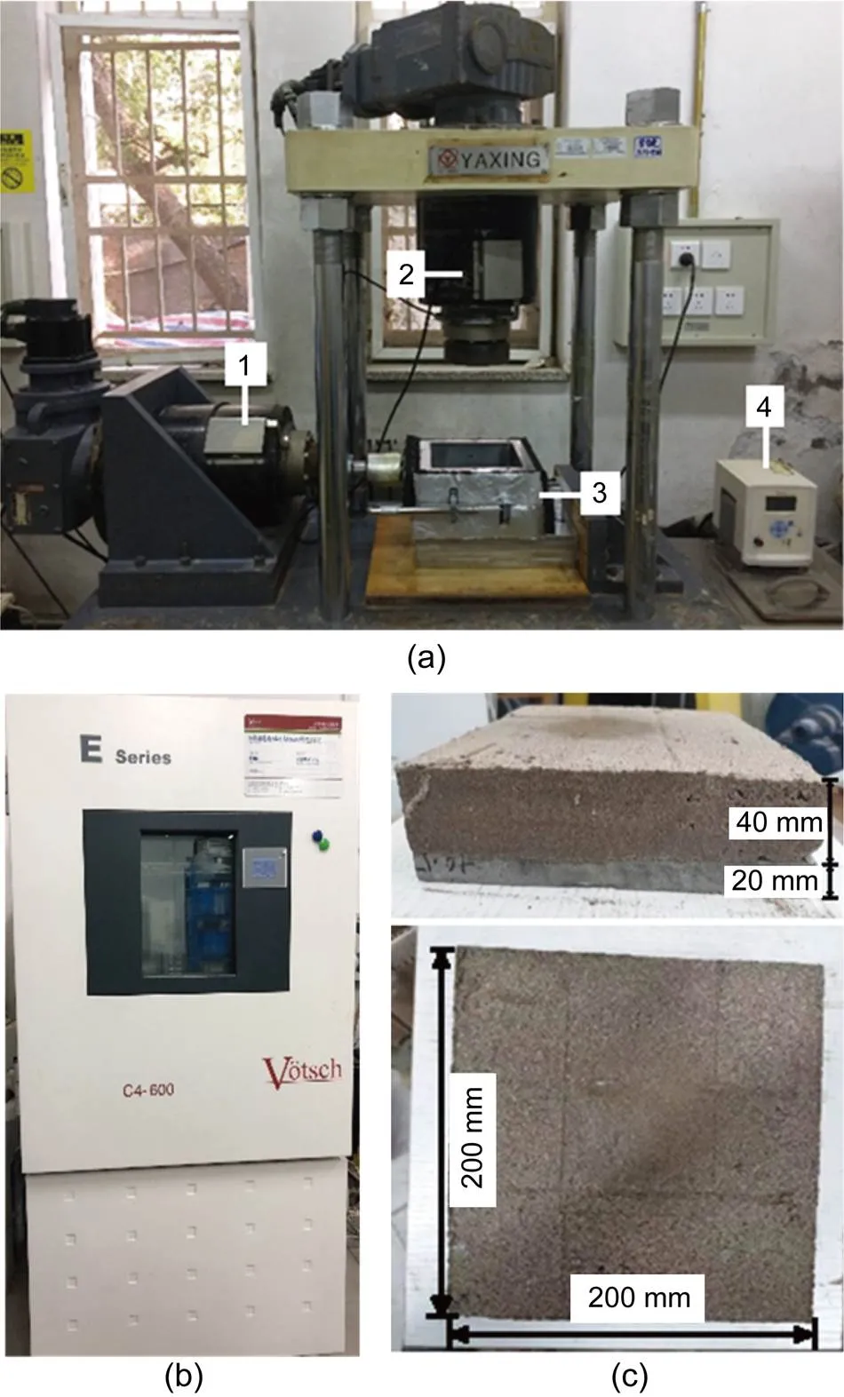
Fig. 1 Test devices and specimen: (a) large-scale direct shear apparatus (1: stepper servomotor for shear loading; 2: stepper servomotor for normal loading; 3: shear boxes; 4: refrigeration system); (b) temperature and humidity chamber; (c) specimen
The specimens were prepared with fine sand (based on the unified soil classification system). The sand parameters are presented in Table 1. The maximum dry density and optimum water content were 1.62 g/cm3and 18%, respectively, based on the ASTM Standards.
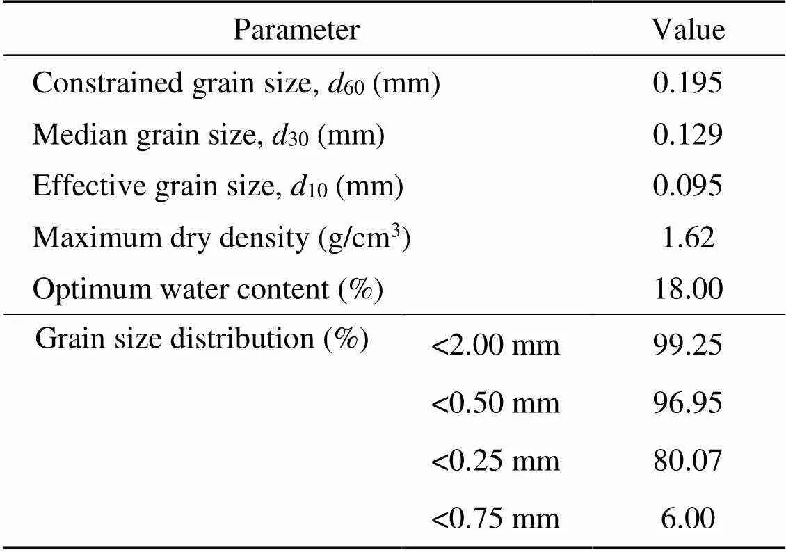
Table 1 Physical properties of the sand for testing
All the artificial frozen sand–concrete specimens were prepared in laboratories, and the preparation processes were as follows.
2.1.1Sand specimen preparation
(1) The undisturbed sand was crushed by pulverising and drying; large particles were removed using a 2-mm sieve, after which the sand was placed in a stove.
(2) The stoved sand was thoroughly mixed with the designed moisture content until saturation, and then set in a sealed plastic bag for 24 h at 1 °C to mix the water and sand fully.
2.1.2Concrete specimen preparation
(1) A layer of Vaseline was spread on the inner surface of the model box with dimensions of 200 mm× 200 mm×20 mm for ease of ejection of the concrete specimen (Fig. 1c).
(2) Thereafter, PO32.5 ordinary Portland cement was mixed with water and fine sand using a 2-mm sieve and poured into model boxes. The consistency of the cement mortar height with respect to the model box was then ensured.
(3) The concrete specimens were cured under standard conditions for 28 d.
(4) The bottom of the concrete specimen was considered as the surface of the structure to ensure that the surfaces of the concrete specimens had the same roughness.
2.1.3Frozen sand–concrete specimen preparation
(1) A layer of petroleum jelly was spread on the inner surface of the model box with dimensions of 200 mm×200 mm×80 mm, for ease of placement of the frozen sand–concrete specimen.
(2) The prepared concrete specimen was placed at the bottom of the model box, which was then filled with three layers of saturated sand according to the designed compaction; the height of the saturated sand sample was 40 mm (Fig. 1c).
(3) The model boxes were wrapped with plastic film and frozen in the temperature and humidity chamber (Fig. 1b) at the designed temperature.
(4) The prepared frozen sand–concrete specimens were rapidly transferred into pre-cooling shear boxes, and cyclic shear tests were conducted.
2.2 Cyclic shear test process
In this study, tests were conducted with CNL and CNH, three initial normal stresses, three negative temperatures, and three amplitudes of cyclic shear loading. The experimental conditions are presented in Table 2.
The stress condition and stress–strain curve of the frozen sand–concrete interface in the shear tests under monotonic and cyclic shear loading are presented in Fig. 2. The initial normal stressn0was applied to the specimen in the vertical direction before the cyclic shear stress was applied, as illustrated in Fig. 2a. Subsequently, the cyclic shear stress was applied in the horizontal direction with a loading pattern of a triangle wave, as shown in Fig. 2b. In this study, the cyclic shear stress is denoted by, whereis the peak shear stress of the frozen sand–concrete interface under monotonic shear loading with the same test conditions as those of the cyclic shear test illustrated in Fig. 2c, and the amplitude of the cyclic shear stress is denoted by=0.2, 0.5, and 0.8. The number of loading cycles is denoted byf=10. The cyclic shear test will be terminated once the total shear displacement reaches 10 mm.
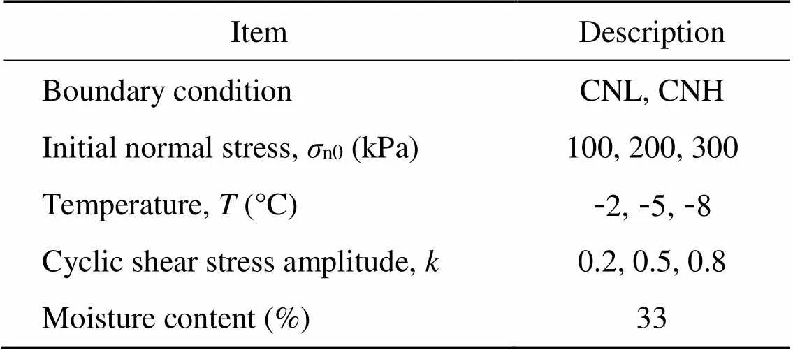
Table 2 Test cases for the frozen sand–concrete interface
Several studies have been reported on the unfrozen soil–structure interface, and a parameterhas been defined to describe the normal stiffness of the interface constraints (Dejong et al., 2003; Dejong and Westgate, 2009). Normal stress is linearly related to volume change via this parameter. According to the influence ofon the interface, the stress paths can be divided into three categories obtained using CNL for=0, CNS for=cst (constant), and CNH for=∞. These three stress paths were obtained by the three different boundary conditions applied to the interface (Saberi et al., 2018b), as shown in Fig. 3. The normal stressncan be calculated using Eq. (1) during shear loading.
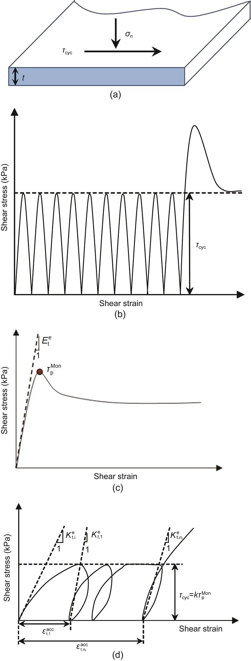
Fig. 2 Scheme of the stress state for the frozen sand–concrete interface: (a) stress variable on the interface plane; (b) cyclic shear loading; (c) shear stress–shear strain (τ-εt) curve of monotonic shear test; (d) shear stress–shear strain (τ-εt) curve of cyclic shear test. t is the thickness of the frozen interface, is the accumulated plastic shear strain of the first cycle, is the accumulated plastic shear strain of the nfth cycle, and other parameters are explaned in the text
(1)
(2)
wheren0is the initial normal stress prior to shear loading, dnis the normal displacement increment of the interface, andis the applied normal stiffness (Saberi et al., 2018b).
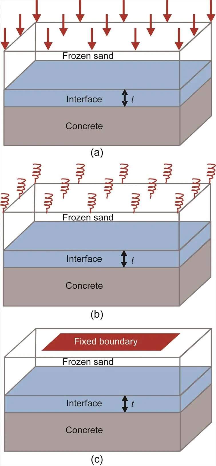
Fig. 3 Schematic view of different boundary conditions in experimental study of the interface: (a) CNL, K=0; (b) CNS, K=cst; (c) CNH, K=∞
3 Evolution of elastic behavior
The shear stress–shear displacement curves of frozen sand–concrete interface under monotonic loading are shown in Fig. 4. The shear stress–shear displacement curves of a frozen sand–concrete interface under cyclic loading, shown in Fig. 5, indicate the influence of initial normal stress, temperature, and cyclic-loading amplitude on shear stress during cyclic loading. The elastic shear modulusis related to the elastic behavior (i.e. the first part of the shear stress–shear strain relationship) under monotonic shear testing. As shown in Figs. 2c and 2d, a tangent to the first part of the-tcurves can be constructed under CNL or CNS monotonic shear loading, andcan be calculated (Fig. 2c). As represented in Fig. 2d, we adopted the methods suggested by previous scholars (Saberi et al., 2018b) regarding the resilient modulus (shear and bulk moduli) as the elastic modulus of the frozen sand–concrete interfaces under cyclic shear loading. The resilient modulus reflects the elastic behaviour of the interface. A complete cycle of the loading process consists of loading, unloading, and reloading processes, and forms a non-closed hysteresis loop (Fig. 2d). In this study, by constructing tangents at the first parts of the-tcurves under CNL, cyclic shear loading testing and the initial elastic shear moduluscould be reached. This study regards the cyclic elastic shear modulusas the slope of the line connecting the inversion point between loading and unloading to the end point in thefth cycle on the-tcurve (Li, 2015). Similarly, the normal elastic modulus can be calculated from the normal stress with respect to the normal displacement data obtained from the CNS tests.
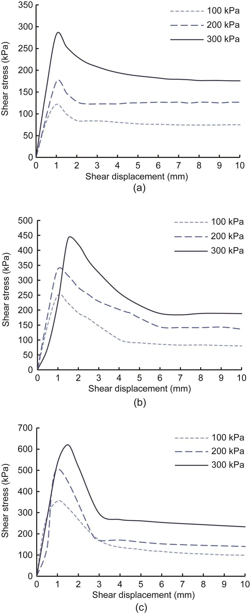
Fig. 4 Shear stress–shear displacement curves of monotonic shear tests: (a) T=-2 °C; (b) T=-5 °C; (c) T=-8 °C
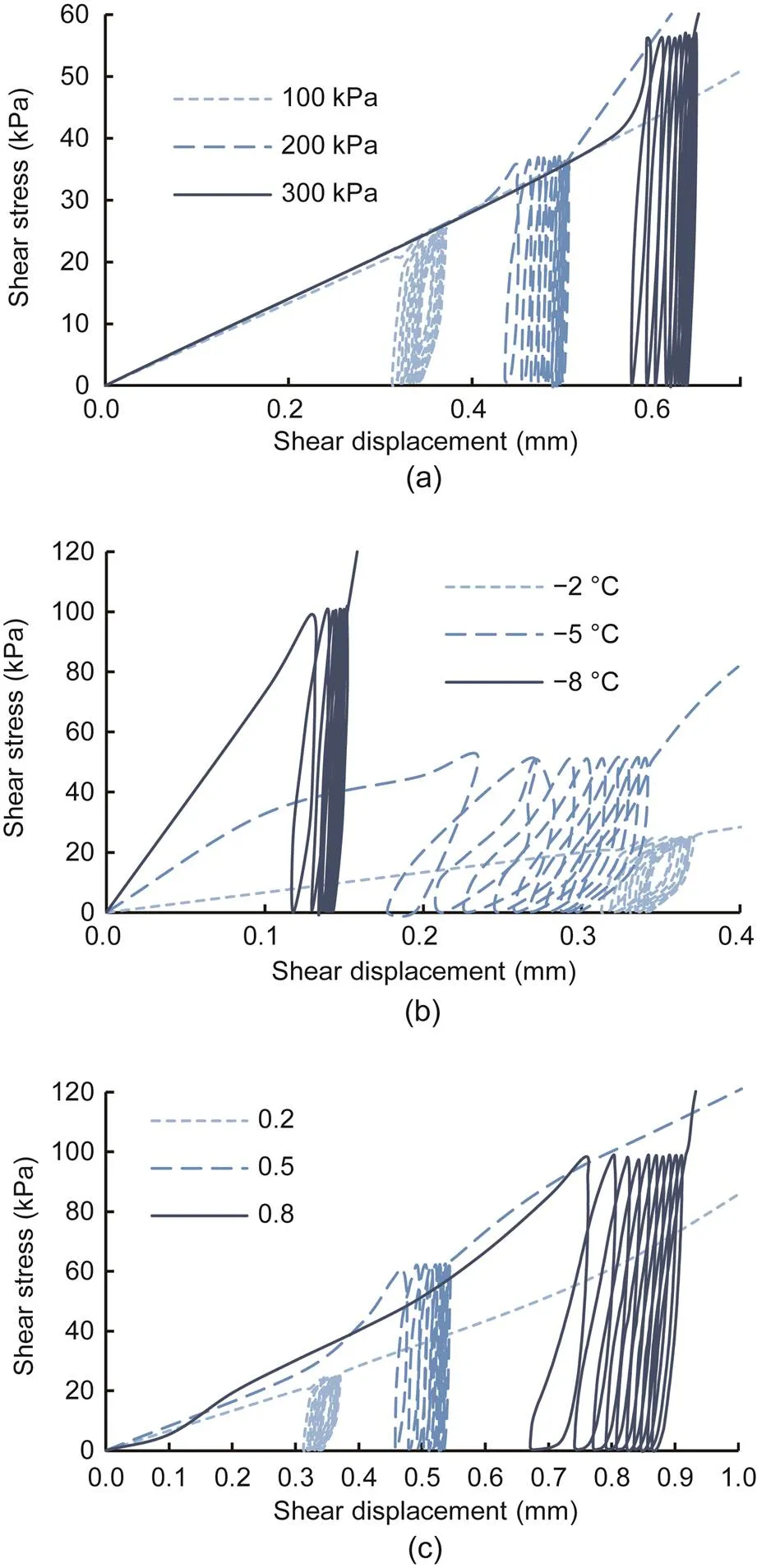
Fig. 5 Shear stress–shear displacement curves of cyclic shear tests: (a) T=-2 °C, k=0.2; (b) k=0.2, σn0=100 kPa; (c) T=-2 °C, σn0=100 kPa
The elastic shear behaviour of the frozen sand–concrete interface was studied based on shear experiments conducted with different initial normal stresses, negative temperatures, and cyclic-loading amplitudes under monotonic and cyclic shear loading.
3.1 Analysis of elastic shear modulus under monotonic shear loading
The effects of the initial normal stress and negative temperature onwith monotonic shear loading under CNL were investigated based on a series of experiments, as shown in Fig. 6.exhibited linear growth as a result of increasing initial normal stress and decreasing temperature.
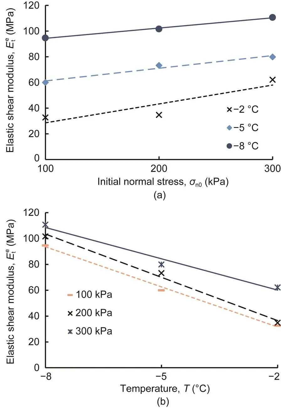
Fig. 6 Elastic shear moduli of monotonic shear test versus initial normal stress (a) and temperature (b)
3.2 Analysis of elastic shear modulus under cyclic shear loading
3.2.1Initial elastic shear modulus
It is commonly acknowledged (Zhang and Zhang, 2006; Saberi et al., 2018b) thatis significantly affected by the normal stress of an unfrozen sand–concrete interface. The factors influencing the elastic modulus of a frozen sand–concrete interface significantly are the initial normal stress and a negative temperature based on the monotonic shear tests described above. The applicability of that conclusion to frozen sand–concrete interfaces under cyclic shear loading was investigated by conducting various tests with different initial normal stresses, negative temperatures, and cyclic-loading amplitudes. The development ofwith the initial normal stress, negative temperature, and cyclic-loading amplitude is shown in Fig. 7. The variation trends ofwith respect to the initial normal stress and negative temperature were identical to those ofin the monotonic shear test. The evolution curves, shown in Figs. 7a and 7b, indicate that the increasing initial normal stress and the decreasing temperature led to a higher. Moreover,was independent of the cyclic-loading amplitude, and differences were not observed for different cyclic-loading amplitudes (Fig. 7c).
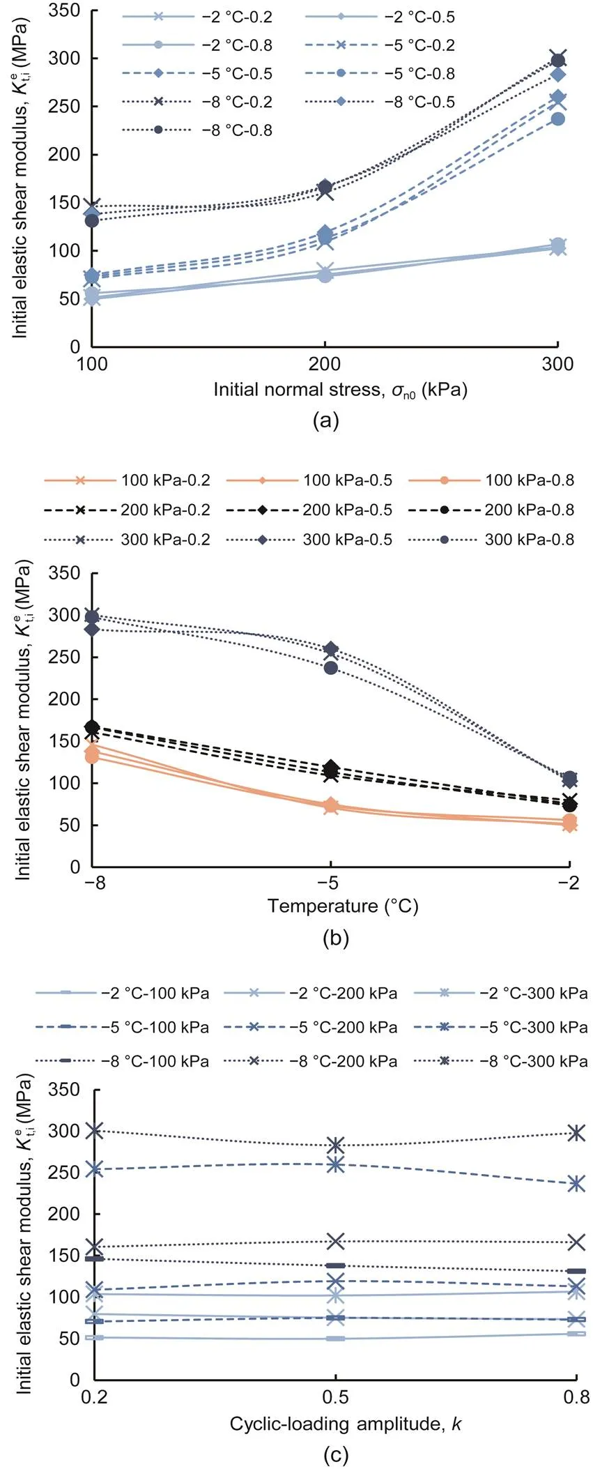
Fig. 7 Initial elastic shear moduli of cyclic shear test versus different initial normal stresses (a), temperatures (b), and cyclic-loading amplitudes (c)
3.2.2Cyclic elastic shear modulus
Fig. 8a illustrates the variations inwith respect to the loading cycles. The dependence ofon the initial normal stress and negative temperature was investigated based on a series of tests with a cyclic-loading amplitude of=0.2. At zero cyclic loading,was equal to. The increasing trend ofwith increasing initial normal stress and decreasing temperature was similar to that ofin the monotonic shear test and that ofin the cyclic shear test. In the same test results,was higher than. Fig. 8a indicates thatfluctuated within a small range with increasing loading cycles.
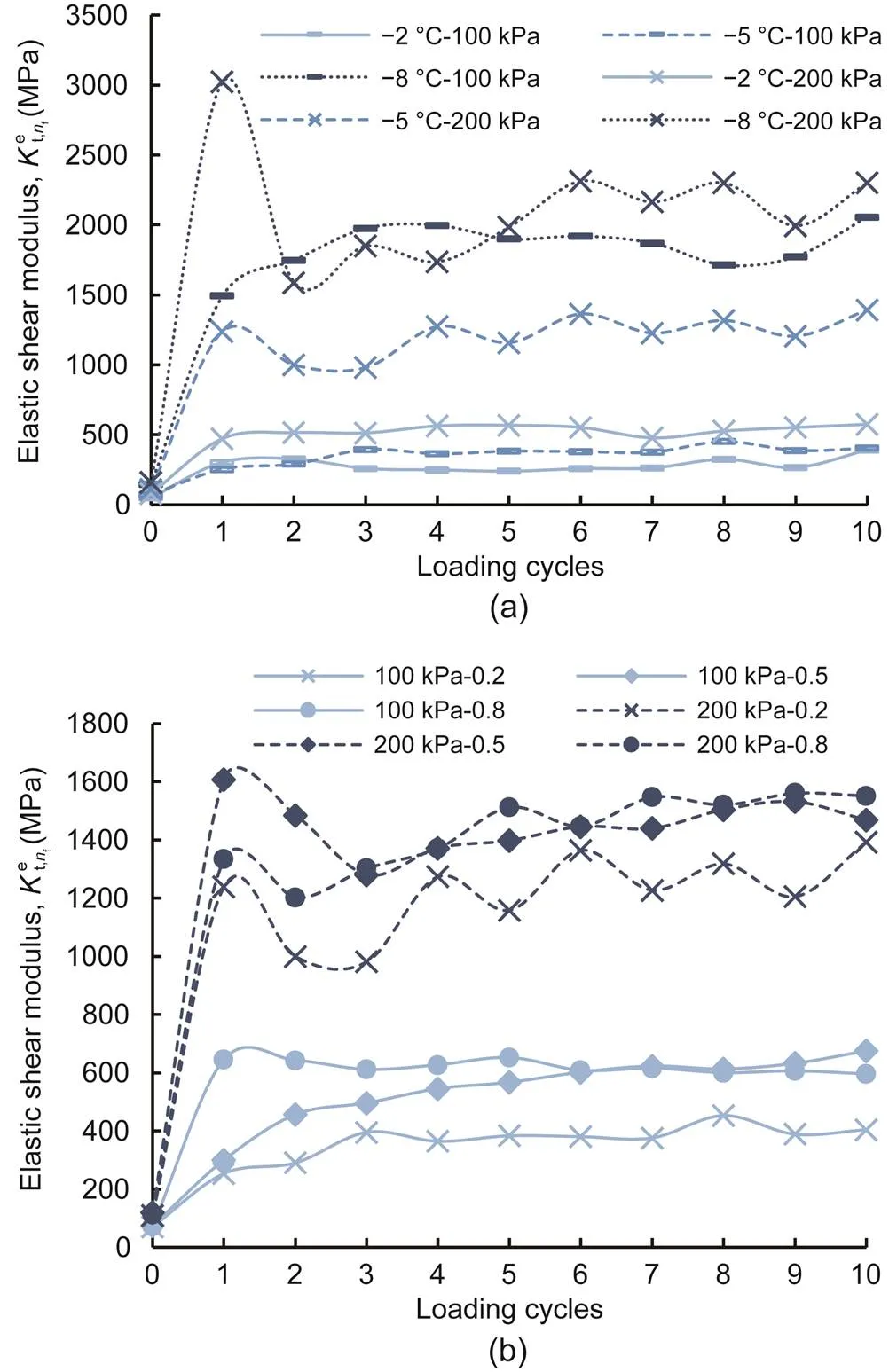
Fig. 8 Cyclic elastic shear moduli of cyclic shear test with different initial normal stresses, temperatures, and cyclic-loading amplitudes versus loading cycles: (a) cyclic-loading amplitude k=0.2; (b) temperature T=-5 °C
Fig. 8b shows the development ofwith the loading cycles, under different cyclic-loading amplitudes, at a temperature of -5 °C. Fig. 8b illustrates that the variations inwith the loading cycles fluctuated within a small range under different cyclic-loading amplitudes. Therefore, the influence of the cyclic-loading amplitude onwas slight.
3.3 Comparison of elastic shear moduli at different stress states
There was negligible impact of the cyclic-loading amplitude onandbased on the above analysis. Therefore, the results forandwere the weighted averages obtained using the values of the different cyclic-loading amplitudes.
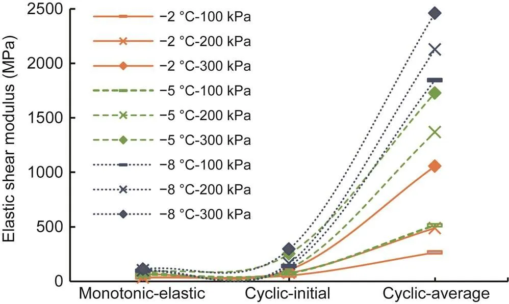
Fig. 9 Elastic shear moduli of different stress states
4 Evolution of interface plastic behavior
The accumulated plastic strain continued to increase with loading cycles according to the tests. As mentioned previously, the initial stress state, stress path, and negative temperature were the factors affecting the characteristics of the accumulated plastic strain (Saberi et al., 2018b). The development of the accumulated plastic strain with increasing initial normal stress, decreasing temperature, and increasing cyclic-loading amplitude under different boundary conditions based on the tests, is discussed below.
4.1 Analysis of accumulated plastic shear strain
4.1.1Influence of initial normal stress
The development of the accumulated plastic shear strain with loading cycles at different initial normal stresses is depicted in Fig. 10, where similar development curves can be observed. During 10 cyclic shear loading cycles, increasing loading cycles decreased the increment of accumulated plastic shear strain and increased the accumulated plastic shear strain.Moreover, higher initial normal stress led to higher accumulated plastic shear strain when the loading cycles and negative temperature were constant. With decreasing temperature, increasing normal stress led to a decreasing increment of the accumulated plastic shear strain of the frozen sand–concrete interface at a given cyclic-loading amplitude under CNL and CNH. However, the initial normal stress affected the frozen interface differently than it did in the study conducted by Pra-ai and Boulon (2017). The results obtained by Pra-ai and Boulon (2017) showed that accumulated shear strain decreased with increasing initial normal stress at a given loading cycle. Compared with the properties of the unfrozen soil, increasing initial mean stress decreased the strength of the frozen soil (Lai et al., 2013; Li, 2015; Li et al., 2016), which can be attributed to the pressure-melting behaviour of frozen soil. Hence, pressure-melting of the frozen sand–concrete interface occurred during cyclic shearing, resulting in contrasting observations of the unfrozen soil–structure interface and the frozen sand–concrete interface.
4.1.2Influence of temperature
The influence of the negative temperature on the accumulated plastic shear strain is illustrated in Fig. 10. When the loading cycles were constant, the higher the temperature, the greater the accumulated plastic shear strain (Fig. 10). With higher initial normal stress, the increment in accumulated plastic shear strain of the frozen sand–concrete interface increased rapidly with increasing temperature at a certain cyclic-loading amplitude under CNL and CNH. Therefore, the dependence of plastic behaviour on the negative temperature was significant. The strength of frozen sand–concrete interfaces is higher than that of unfrozen sand–concrete interfaces; this can be mainly attributed to the cementing of ice between the sand and concrete and indicates that the unfrozen water film surrounding the soil particles affects the strength of the frozen sand–concrete interface (Akagawa and Nishisato, 2009; Lai et al., 2009a). When the initial moisture content was constant, the unfrozen water film became thinner as the temperature of the frozen sand–concrete interface decreased, contributing to a higher strength of the frozen interface that can resist the deformation. When the loading cycles were constant, the accumulated plastic shear strain and accumulation increment were lower when the temperature was lower, as shown in Fig. 10.
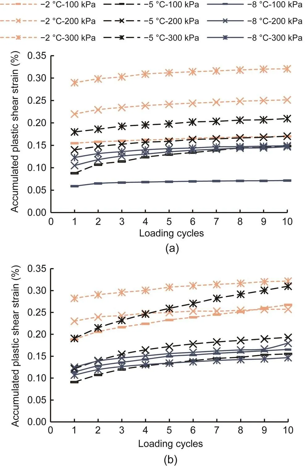
Fig. 10 Accumulated plastic shear strain with different initial normal stresses and temperatures versus loading cycles under CNL and CNH: (a) CNL, k=0.2; (b) CNH, k=0.2
4.1.3Influence of cyclic shear stress amplitude
Tests of the frozen sand–concrete interface were conducted with different cyclic-loading amplitudes at identical initial normal stress, three different negative temperatures, and different boundary conditions. As the loading cycles continued, more plastic shear strain was accumulated and the similar accumulation curves were observed under different cyclic-loading amplitudes. In each cyclic loading test, the accumulation increment decreased as the loading cycles increased. Furthermore, increasing cyclic-loading amplitude contributed to increasing accumulated plastic shear strain when the loading cycles were constant, as illustrated in Fig. 11.
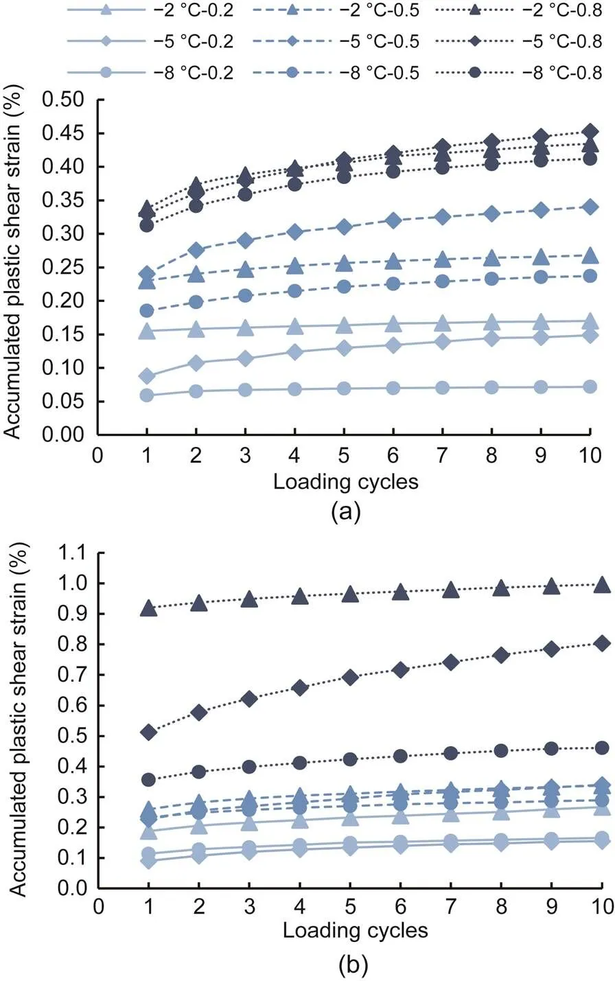
Fig. 11 Accumulated plastic shear strain with different cyclic-loading amplitudes and temperatures versus loading cycles under CNL and CNH: (a) CNL, σn0=100 kPa; (b) CNH, σn0=100 kPa
4.1.4Influence of boundary conditions
The accumulated plastic shear strain and accumulation increment of CNH were higher than those of CNL at a given initial normal stress, negative temperature, and cyclic-loading amplitude, as shown in Figs. 10 and 11. When the initial normal stress and the cyclic-loading amplitude increased and the negative temperature decreased, there was a more significant increase in the accumulation increment of CNH than that of CNL. For identical initial normal stress with CNH, when the shear displacement was sufficiently large, the normal stress decreased during the shearing of the frozen sand–concrete interface. Hence, a higher accumulated plastic shear strain and accumulation increment of CNH was observed.
4.2 Analysis of accumulation direction
The hypothesis in this study is that the normal stress acts on the entire test sample and the shear load acts only on the interface. As observed in previous studies, the vertical displacementsmeasured at the top of the specimen is different from the vertical displacementimeasured at the top of the frozen sand–concrete interface after the application of the initial normal stress in the initial phase of a direct shear test, hereafter referred to as the normal relative displacement, as shown in Fig. 2. The relationship between the variables can be expressed as follows (Pra-ai and Boulon, 2017):
(3)
whereis the initial height of the specimen, andis the initial thickness of the frozen sand–concrete interface, where≠. The thickness of the frozen sand–concrete interface needs to be obtained from experiment or taken as an empirical value based on previous studies (Lashkari, 2012; Saberi et al., 2016; Yang et al., 2016). For simplicity, in this study,swas selected as the normal displacement of the frozen sand–concrete interface. The normal displacement was defined as compression.
We investigated the development trend of the accumulated plastic volumetric strainwith increasing accumulated plastic shear strain.
The direction of the accumulated plastic strain increment was defined by a vectorand a non-associated flow rule was introduced based on the elastoplastic constitutive model established by Lashkari (2012, 2013) and Saberi et al. (2016, 2018b). The direction of the plastic strain increment was introduced as follows:
(4)
whereis the yield function of interface, andis the shear stress of interface. Eq. (4) indicates thattis defined along the shear direction of the yield surface, which determines the plastic shear displacement, andnis defined as the dilatancy coefficientto determine the plastic normal displacement. The dilatancy coefficientdetermines the direction of plastic shear strain accumulation;in Eq. (4) is an auxiliary parameter, and(Lashkari, 2012, 2013). The relationships between accumulated plastic volumetric strain and accumulated plastic shear strain influenced by initial normal stress, negative temperature, and cyclic-loading amplitude, were observed in Figs. 12–16. The results showed that the accumulated plastic volumetric strain increased rapidly with increasing accumulated plastic shear strain, and the increasing trend was non-linear. Also, according to Eq. (4), the accumulated direction is defined as the slope of the curve of-. Therefore, an empirical function is formulated to describe their relationship as
(5)
and then the direction of accumulated plastic strain can be obtained using Eq. (5):
(6)
(7)
where0is the initial direction of accumulated plastic strain. In particular,andare the fitting parameters from Eqs. (5) and (6). The accumulated strain paths-from the tests with different initial normal stresses, negative temperatures, and cyclic-loading amplitudes were analysed with respect to their influences on the accumulated direction, as presented in the following sections.
4.2.1Influence of initial normal stress
The accumulated plastic strain paths-at different initial normal stresses are depicted in Fig. 12. The results show that the plastic volumetric strain accumulated with decreasing initial normal stress when the accumulated plastic shear strain was constant, and the accumulation progressed as the accumulated plastic shear strain grew when the initial normal stress was constant. However, the increment in accumulated plastic volumetric strain decreased with increasing accumulated plastic shear strain when the initial normal stress was constant. The accumulated plastic strain was mainly affected by shear strain. The variations of the parameters (the initial direction of accumulated plastic strain0and the fitting parametersand) in Eqs. (5) and (6) with the initial normal stress, are presented in Fig. 13. Figs. 13a and 13c show that0anddecreased as the initial normal stress increased. Fig. 13b reveals thatwas irregular when the initial normal stress increased in all tests, indicating that the initial normal stress had no effect on.
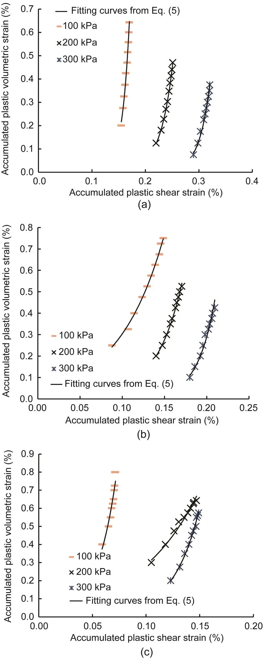
Fig. 12 Accumulated plastic volumetric strain with different initial normal stresses versus accumulated plastic shear strain: (a) T=-2 °C, k=0.2; (b) T=-5 °C, k=0.2; (c) T=-8 °C, k=0.2
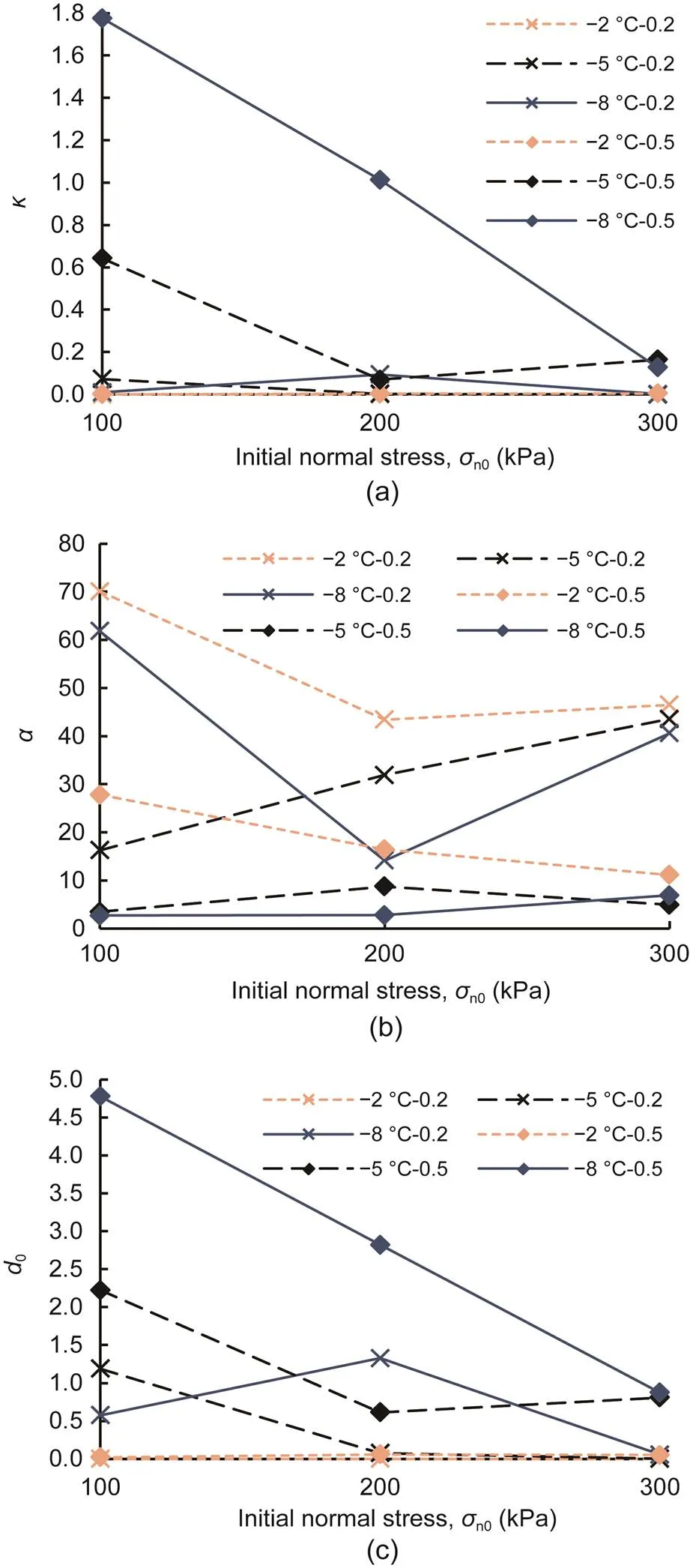
Fig. 13 Parameters κ (a), α (b), and d0 (c) from curves versus initial normal stress
4.2.2Influence of temperature
Fig. 14 presents the accumulated plastic strain paths-obtained in the tests conducted at different temperatures, and exhibits clear trends. The accumulated plastic volumetric strain increased significantly with decreasing temperature at a given accumulated plastic shear strain, and the increment in the accumulated plastic volumetric strain decreased with increasing accumulated plastic shear strain at a given negative temperature, as shown in Fig. 14. The effects of different temperatures on the parameters (0,, and) in Eqs. (5) and (6) are illustrated in Fig. 15.0andincreased significantly with decreasing temperature and approached given values when the temperature increased.decreased slightly with decreasing temperature, and the variations at different temperatures were slight. Therefore,was deemed independent of the temperature.
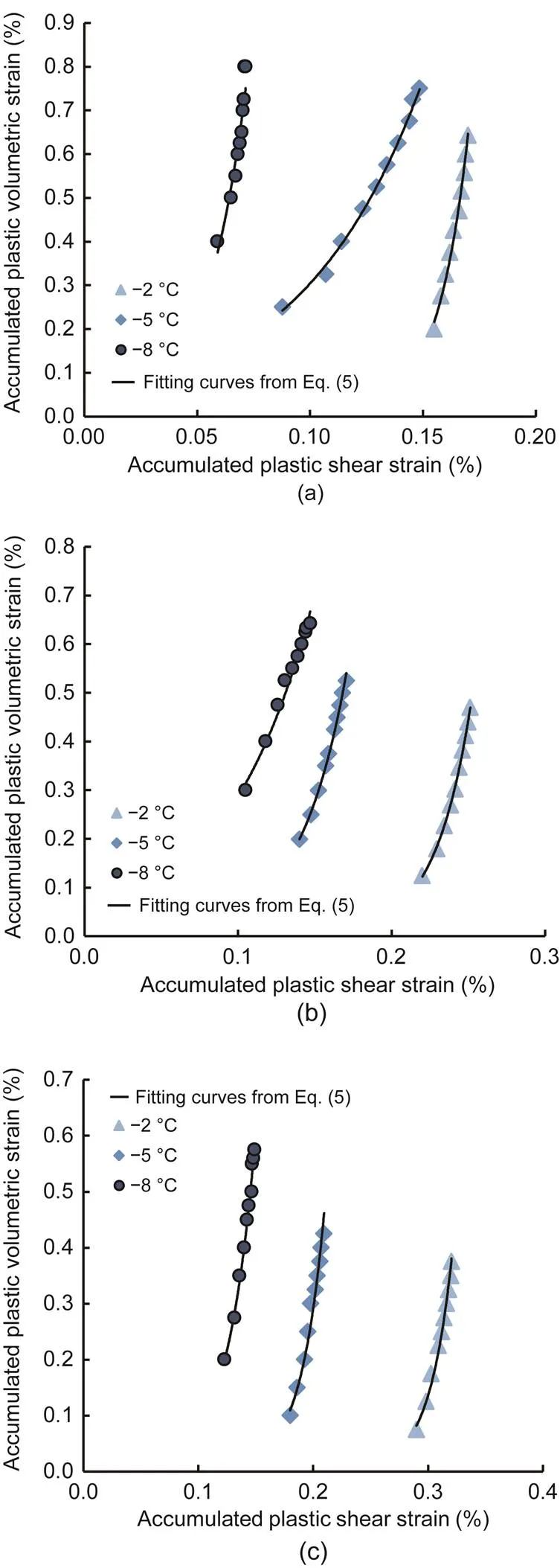
Fig. 14 Accumulated plastic volumetric strain with different temperatures versus accumulated plastic shear strain: (a) σn0=100 kPa, k=0.2; (b) σn0=200 kPa, k=0.2; (c) σn0=300 kPa, k=0.2
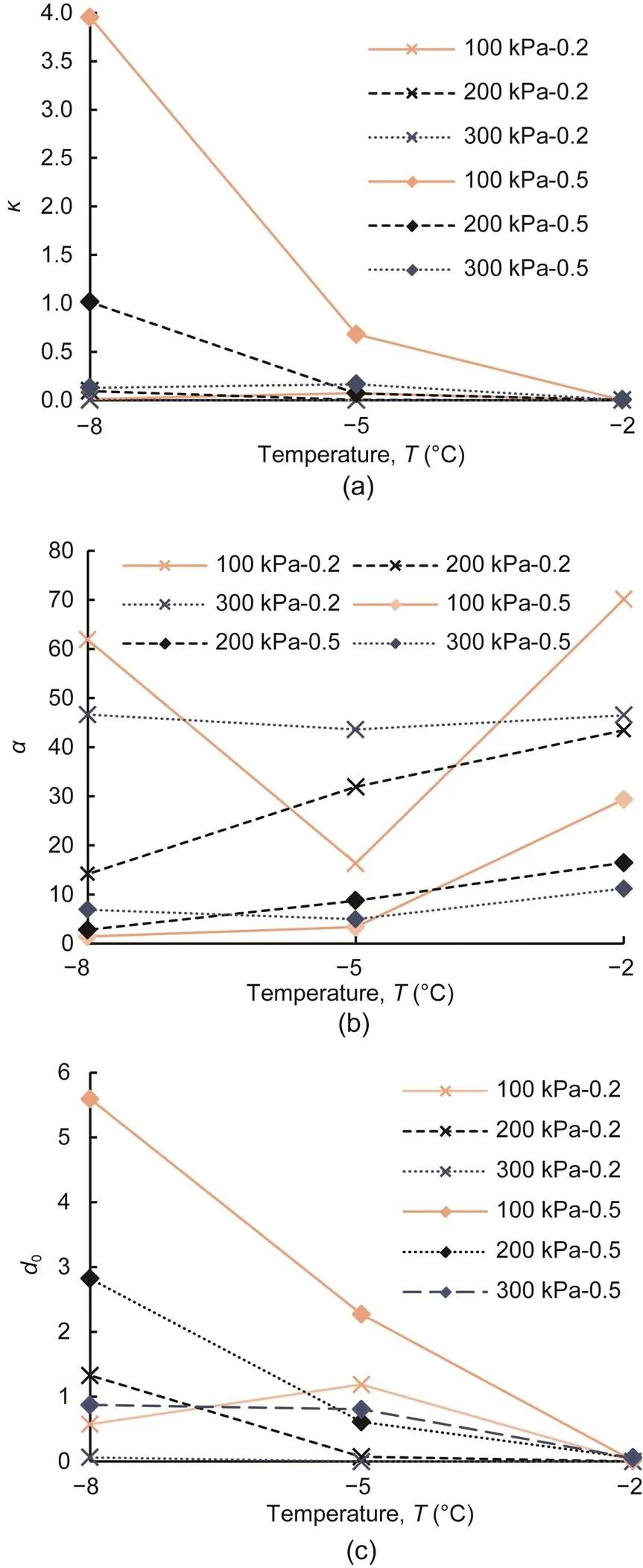
Fig. 15 Parameters κ (a), α (b), and d0 (c) from curves versus temperature
4.2.3Influence of cyclic-loading amplitude
Fig. 16 depicts the accumulated plastic strain paths-under different cyclic-loading amplitudes. The plastic volumetric strain increased as the cyclic-loading amplitude decreased when the accumulated plastic shear strain was constant, and the accumulation continued to progress with increasing accumulated plastic shear strain when the cyclic-loading amplitude was constant. The higher the accumulated plastic shear strain, the lower was the increment in accumulated plastic volumetric strain, when the cyclic-loading amplitude was constant, as shown in Fig. 16. The effect of the cyclic-loading amplitude on the accumulated direction (0,, and) was also investigated. Fig. 17 shows the relationship between the three parameters and the cyclic-loading amplitude. The cyclic-loading amplitude had significant effects on0,, and.and0exhibited an increasing trend when the cyclic-loading amplitude increased, andshowed a significant decreasing trend when the cyclic-loading amplitude increased.
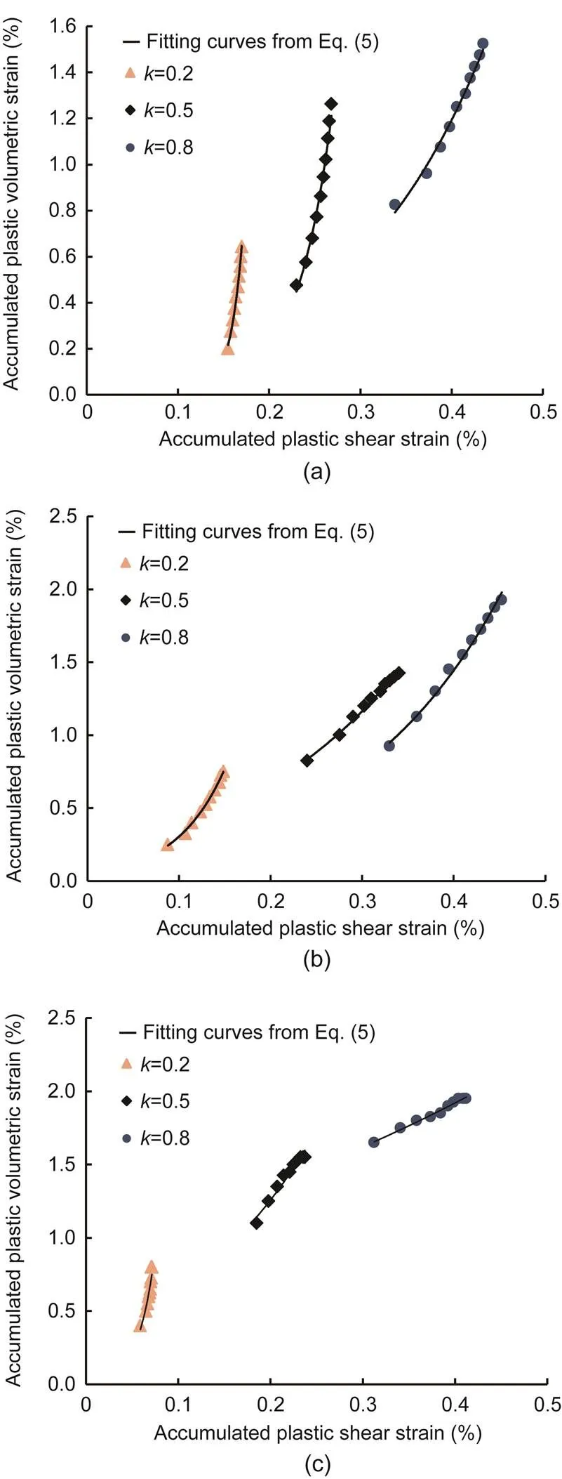
Fig. 16 Accumulated plastic volumetric strain with different cyclic-loading amplitudes versus accumulated plastic shear strain: (a) T=-2 °C, σn0=100 kPa; (b) T= -5 °C, σn0=200 kPa; (c) T=-8 °C, σn0=300 kPa
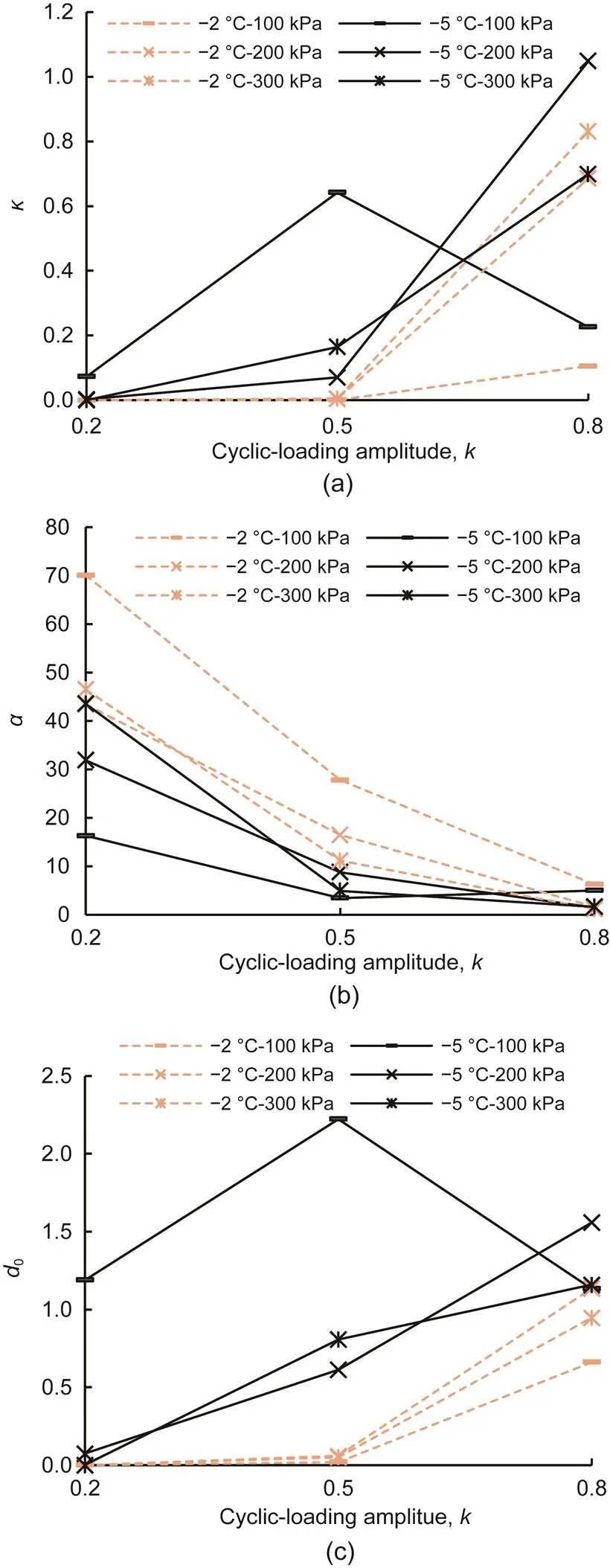
Fig. 17 Parameters κ (a), α (b), and d0 (c) from curves versus cyclic-loading amplitude
5 Evolution of peak shear stress and critical shear stress
5.1 Influence of the initial normal stress
At different negative temperatures and cyclic-loading amplitudes, the increasing trend of the peak shear stress with increasing initial normal stress was the same as that of the critical shear stress, as shown in Figs. 18 and 19, where 'Mon.' denotes the monotonic shear test. A linear relationship was observed between the peak shear stress and the increasing initial normal stress and between the critical shear stress and the increasing initial normal stress, under both boundary conditions. The peak shear stress of the frozen sand–concrete interface in the cyclic shear tests was higher than that in the monotonic shear tests at a given initial normal stress and negative temperature, as shown in Figs. 18a and 19a. However, there was a slight difference in the critical shear stress between the cyclic and monotonic shear tests, as shown in Figs. 18b and 19b.
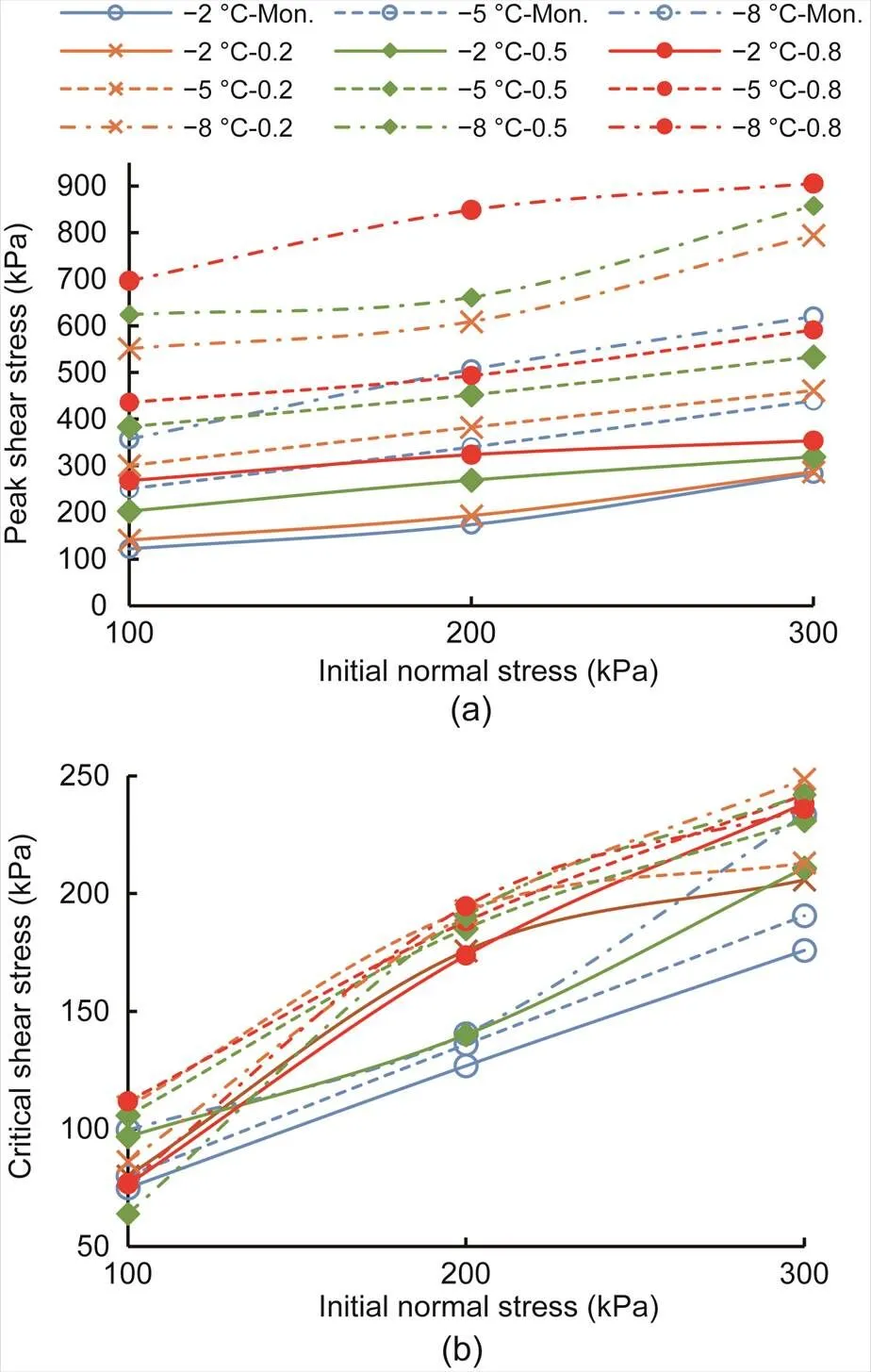
Fig. 18 Peak shear stress (a) and critical shear stress (b) with different temperatures and cyclic-loading amplitudes versus initial normal stress under CNL
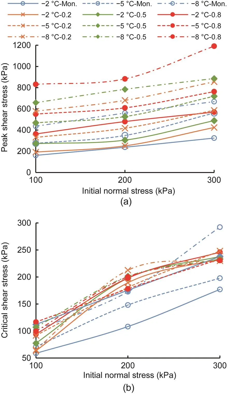
Fig. 19 Peak shear stress (a) and critical shear stress (b) with different temperatures and cyclic-loading amplitudes versus initial normal stress under CNH
5.2 Influence of temperature
The influences of the negative temperature on the peak shear stress and critical shear stress with respect to different initial normal stresses and cyclic-loading amplitudes under CNL and CNH are illustrated in Figs. 20 and 21, respectively. As shown in Figs. 20a and 21a, both boundary conditions had a common rule: the lower the temperature, the higher the peak shear stress. Also, the peak shear stress under cyclic shear stress was higher than that under monotonic shear stress. The critical shear stress was independent of temperature under both boundary conditions, and the critical shear stress was not influenced by the cyclic-loading amplitude, as shown in Figs. 20b and 21b. The primary influencing factors on the frozen sand–concrete interface were the ice-cementing strength and the friction between the sand and concrete. The ice-cementing strength deteriorated after the peak point of the stress–strain curve, and the shear strength at the residual shear stage of the frozen interface was supported by the friction strength between the frozen sand and concrete. Therefore, the critical shear strength of the frozen interface was independent of the negative temperature.
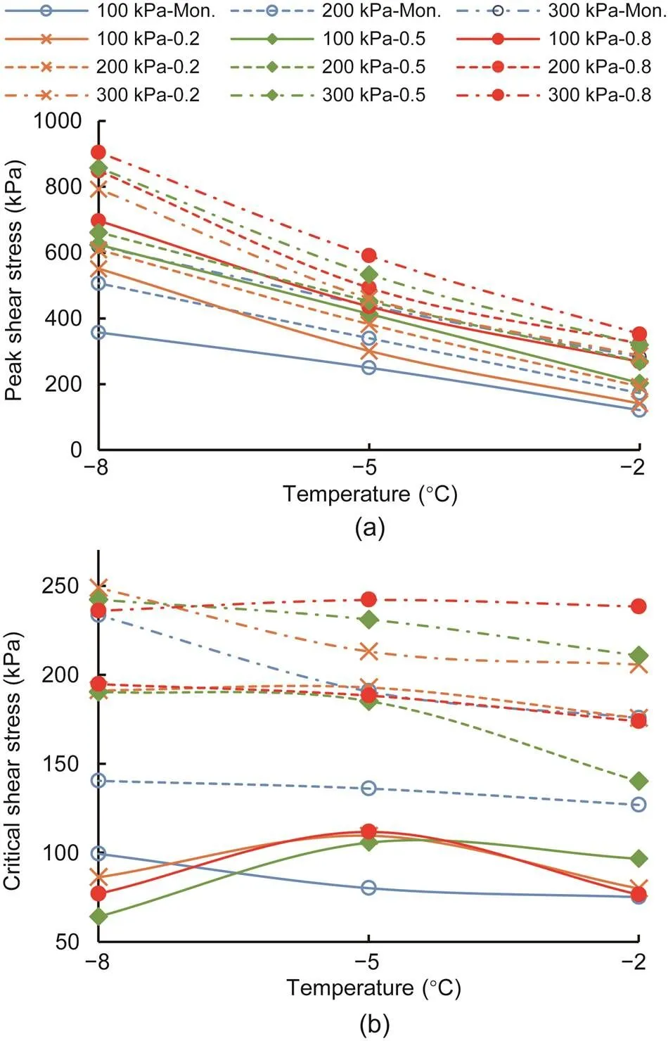
Fig. 20 Peak shear stress (a) and critical shear stress (b) with different initial normal stresses and cyclic-loading amplitudes versus temperature under CNL
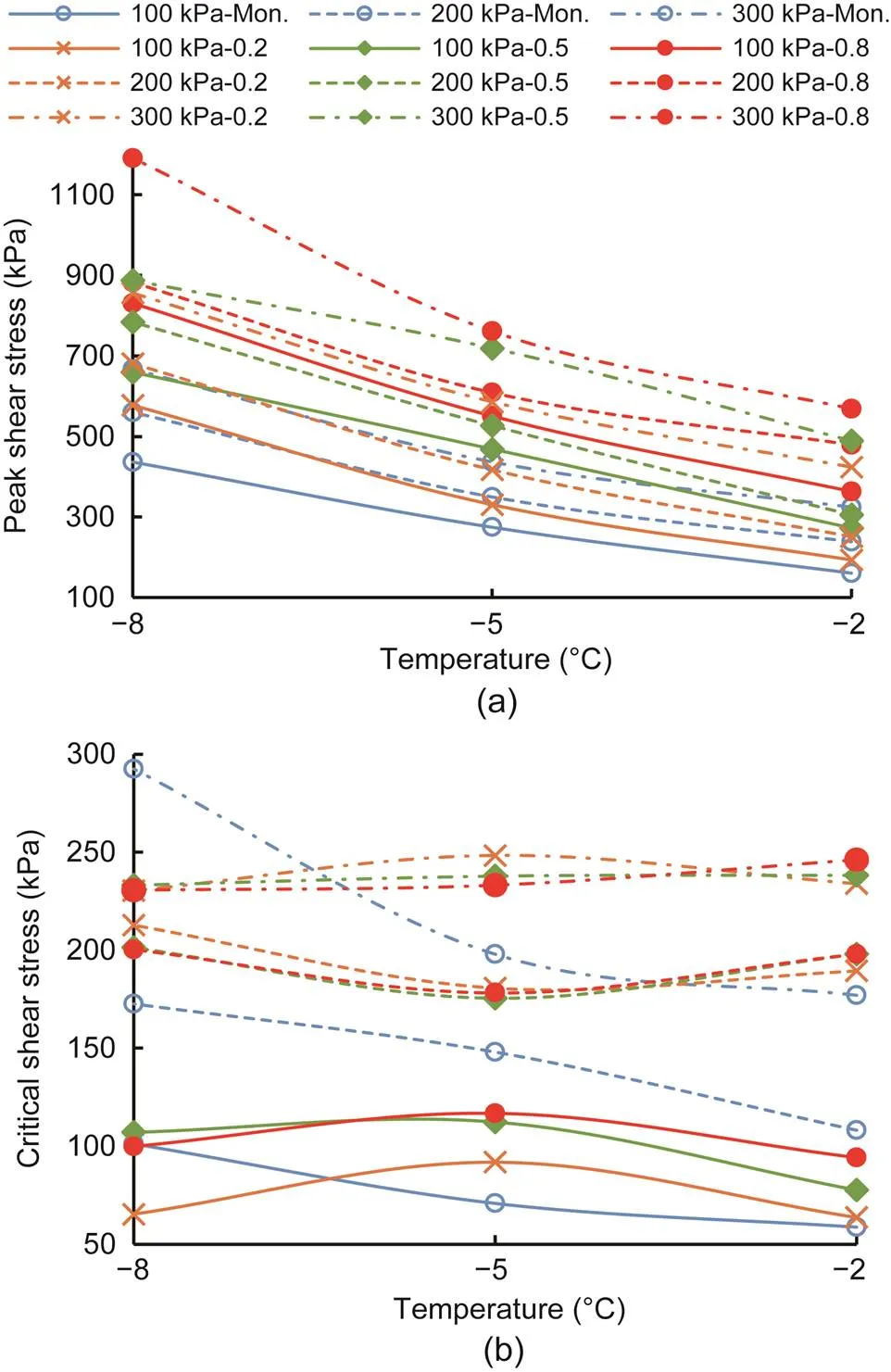
Fig. 21 Peak shear stress (a) and critical shear stress (b) with different initial normal stresses and cyclic-loading amplitudes versus temperature under CNH
5.3 Influence of cyclic-loading amplitude
The development trends of the peak shear stress and critical shear stress with increasing cyclic-loading amplitude, under CNL and CNH, are presented in Figs. 22 and 23, respectively. According to Figs. 22a and 23a, the peak shear stress of the frozen sand–concrete interface increased with the cyclic-loading amplitude at a given negative temperature and initial normal stress and under both boundary conditions. In addition, the cyclic-loading amplitude had no influence on the critical shear stress, as observed in Figs. 22b and 23b.
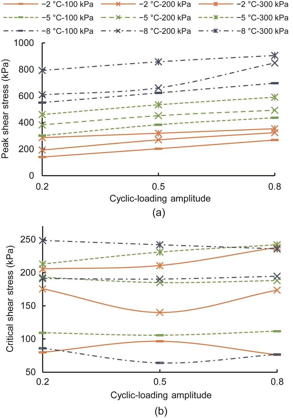
Fig. 22 Peak shear stress (a) and critical shear stress (b) with different initial normal stresses and temperatures versus cyclic-loading amplitude under CNL
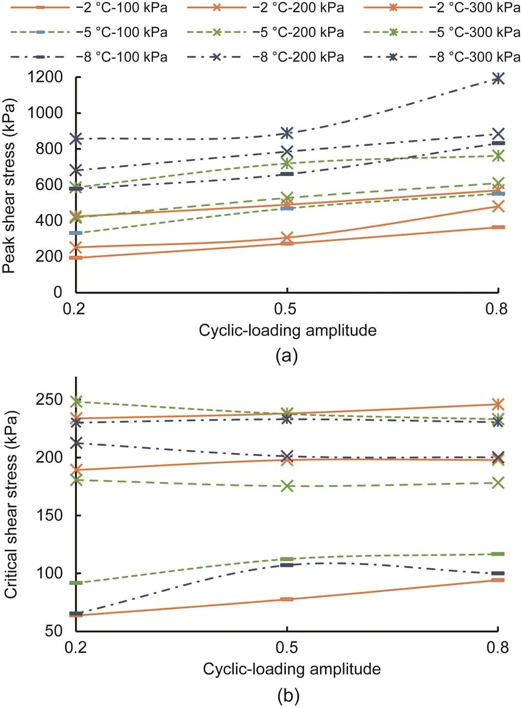
Fig. 23 Peak shear stress (a) and critical shear stress (b) with different initial normal stresses and temperatures versus cyclic-loading amplitude under CNH
5.4 Influence of boundary condition
As can be observed from Figs. 18–23, the peak shear stress and critical shear stress under CNL of the frozen interface at a given negative temperature and cyclic-loading amplitude were almost the same as those under CNH. A higher peak shear stress and lower critical shear stress were observed under CNH than those under CNL; this observation was consistent with the influence of the boundary condition on the peak shear stress and critical shear stress in the monotonic shear tests. This behavior can be attributed to the dilatancy of ice between sand and concrete, which occurred during initial shearing and led to a higher normal stress under CNH. Moreover, the normal stress was constant under CNL, which led to a higher peak shear stress under CNH. Ice failure of the cementing strength and compression of the frozen sand–concrete interface occurred with increasing displacement in the shear, leading to a lower normal stress under CNH. Therefore, the critical shear stress under CNH was lower than that under CNL.
6 Conclusions
This study investigated the elastoplastic characteristics of a frozen sand–concrete interface using a self-developed large-scale direct shear apparatus. The elastoplastic behavior of the frozen sand–concrete interface was evaluated and compared under various initial normal stresses, negative temperatures, cyclic-loading amplitude, and boundary conditions. The main conclusions of this study are as follows:
(1) The initial elastic shear modulus and cyclic elastic shear modulus increase when the initial normal stress increases and temperature decreases. However, the cyclic-loading amplitude has a negligible influence on the elastic shear modulus (including the initial elastic shear modulus and cyclic elastic shear modulus) under cyclic shear stress. The cyclic elastic shear modulus fluctuates within a small range when the cyclic-loading amplitude increases, indicating that the cyclic-loading amplitude has a slight influence on the cyclic elastic shear modulus.
(2) The relationship among the elastic shear modulus under monotonic shear stress, initial elastic shear modulus, and cyclic elastic shear modulus under cyclic shear stress can be described by an exponential function.
(3) Under CNL and CNH, the plastic shear strain of frozen sand–concrete interfaces increases and the accumulation increment of the frozen sand–concrete interfaces decreases, when the loading cycles increases. Moreover, the lower the temperature, the lower the increment in accumulated plastic shear strain, which increases with normal stress at a given cyclic-loading amplitude. The lower the initial normal stress, the less the increment in accumulated plastic shear strain, which increases with negative temperature at a given cyclic-loading amplitude.
(4) The effects of the initial normal stress, negative temperature, and cyclic-loading amplitude on the accumulated plastic shear strain and accumulated plastic volumetric strain are significant. The accumulated plastic shear strain and accumulated plastic volumetric strain increase with increasing initial normal stress, increasing cyclic-loading amplitude, and decreasing temperature in the same loading cycle.
(5) The test results show that an exponential function can describe the relationship between the direction of accumulated plastic strain increment and the accumulated plastic shear strain. We analysed the relationships between the direction of accumulated plastic strain increment and the initial normal stress, negative temperature, and cyclic-loading amplitude in detail.
(6) When the initial normal stress increases, the temperature decreases, and the cyclic-loading amplitude increases, under CNL and CNH, the peak shear stress increases significantly. The experimental results confirmed these behaviors. The critical shear stress increased with the initial normal stress under both boundary conditions. However, the critical shear stress is independent of the negative temperature and cyclic-loading amplitude under both boundary conditions.
(7) The peak shear stress under CNH is higher than that under CNL, and the critical shear stress under CNH is lower than that under CNL at a given initial normal stress. The accumulated plastic shear strain under CNL is higher than that under CNH.
(8) The elastoplastic behaviour of the frozen sand–concrete interface in this study is consistent with certain behavioural aspects of the unfrozen sand–concrete interface. However, the ice cementation between the soil and concrete results in specific mechanical behaviors of the frozen soil–concrete interface, which indicate that an appropriate constitutive model should be established for frozen sand–concrete interfaces under cyclic shear loading.
This work is supported by the National Natural Science Foundation of China (No. 41731281) and the Key Foundation of Guangdong Province (No. 2020B1515120083), China.
Jian CHANG and Jian-kun LIU designed the research and processed the corresponding data. Jian CHANG and Ya-li LI wrote the first draft of the manuscript. Qi WANG and Zhong-hua HAO helped to organize the manuscript. Jian CHANG revised and edited the final version.
Jian CHANG, Jian-kun LIU, Ya-li LI, Qi WANG, and Zhong-hua HAO declare that they have no conflict of interest.
Aghakouchak A, Sim WW, Jardine RJ, 2015. Stress-path laboratory tests to characterise the cyclic behaviour of piles driven in sands., 55(5):917-928. https://doi.org/10.1016/j.sandf.2015.08.001
Akagawa S, Nishisato K, 2009. Tensile strength of frozen soil in the temperature range of the frozen fringe., 57(1):13-22. https://doi.org/10.1016/j.coldregions.2009.01.002
Aldaeef AA, Rayhani MT, 2018. Impact of ground warming on pile-soil interface strength in ice-poor frozen soils. GeoEdmonton 2018.
Aldaeef AA, Rayhani MT, 2019a. Interface shear strength characteristics of steel piles in frozen clay under varying exposure temperature., 59(6):2110-2124. https://doi.org/10.1016/j.sandf.2019.11.003
Aldaeef AA, Rayhani MT, 2019b. Load transfer and creep behavior of open-ended pipe piles in frozen and unfrozen ground., 4(1):60. https://doi.org/10.1007/s41062-019-0248-6
Aldaeef AA, Rayhani MT, 2020. Load transfer of pile foundations in frozen and unfrozen soft clay., 14(6):653-664. https://doi.org/10.1080/19386362.2019.1667127
Aldaeef AA, Rayhani MT, 2021. Pile-soil interface characteristics in ice-poor frozen ground under varying exposure temperature., 191:103377. https://doi.org/10.1016/j.coldregions.2021.103377
Cui YH, Liu JK, Lü P, 2013. Development of dynamic load direct shear apparatus for frozen soils., 34(S2):486-490 (in Chinese). https://doi.org/10.16285/j.rsm.2013.s2.066
Dejong JT, Randolph MF, White DJ, 2003. Interface load transfer degradation during cyclic loading: a microscale investigation., 43(4):81-93. https://doi.org/10.3208/sandf.43.4_81
Dejong JT, Westgate ZJ, 2009. Role of initial state, material properties, and confinement condition on local and global soil-structure interface behavior., 135(11):1646-1660. https://doi.org/10.1061/(ASCE)1090-0241(2009)135:11(1646)
Fakharian K, 1996. Three-Dimensional Monotonic and Cyclic Behaviour of Sand–Steel Interfaces: Testing and Modelling. PhD Thesis, University of Ottawa, Ottawa, Canada.
Feng GL, 2009. Study on the cracks on permafrost embankment during the operation of Qinghai-Tibet railway., 19(11):136-139 (in Chinese). https://doi.org/10.3969/j.issn.1005-6033.2009.11.065
Hanzawa H, Nutt N, Lunne T, et al., 2007. A comparative study between the NGI direct simple shear apparatus and the Mikasa direct shear apparatus., 47(1):47-58. https://doi.org/10.3208/sandf.47.47
He PF, Mu YH, Yang ZH, et al., 2020. Freeze-thaw cycling impact on the shear behavior of frozen soil-concrete interface., 173:103024. https://doi.org/10.1016/j.coldregions.2020.103024
He PF, Mu YH, Ma W, et al., 2021. Testing and modeling of frozen clay–concrete interface behavior based on large-scale shear tests., 12(1):83-94. https://doi.org/10.1016/j.accre.2020.09.010
Jardine R, Chow F, Overy R, et al., 2005. ICP Design Methods for Driven Piles in Sands and Clays. Thomas Telford, London, UK.
Lai YM, Zhang Y, Zhang SJ, et al., 2009a. Experimental study of strength of frozen sandy soil under different water contents and temperatures., 30(12):3665-3670 (in Chinese). https://doi.org/10.3969/j.issn.1000-7598.2009.12.018
Lai YM, Jin L, Chang XX, 2009b. Yield criterion and elasto-plastic damage constitutive model for frozen sandy soil., 25(6):1177-1205. https://doi.org/10.1016/j.ijplas.2008.06.010
Lai YM, Xu XX, Dong YB, et al., 2013. Present situation and prospect of mechanical research on frozen soils in China., 87:6-18. https://doi.org/10.1016/j.coldregions.2012.12.001
Lashkari A, 2012. A plasticity model for sand-structure interfaces., 19(4):1098-1108. https://doi.org/10.1007/s11771-012-1115-1
Lashkari A, 2013. Prediction of the shaft resistance of nondisplacement piles in sand., 37(8):904-931. https://doi.org/10.1002/nag.1129
Li QL, 2015. Dynamic Behaviour and Elasto-Plastic Model of Frozen Soil Subjected to Reapeated Cyclic Loading. PhD Thesis, Harbin Institute of Technology, Harbin, China (in Chinese).
Li QL, Ling XZ, Sheng DC, 2016. Elasto-plastic behaviour of frozen soil subjected to long-term low-level repeated loading, part I: experimental investigation., 125:138-151. https://doi.org/10.1016/j.coldregions.2015.11.015
Li XS, Dafalias YF, 2000. Dilatancy for cohesionless soils., 50(4):449-460. https://doi.org/10.1680/geot.2000.50.4.449
Ling XZ, Li QL, Wang LN, et al., 2013. Stiffness and damping radio evolution of frozen clays under long-term low-level repeated cyclic loading: experimental evidence and evolution model., 86:45-54. https://doi.org/10.1016/j.coldregions.2012.11.002
Liu HB, Song EX, Ling HI, 2006. Constitutive modeling of soil-structure interface through the concept of critical state soil mechanics., 33(4):515-531. https://doi.org/10.1016/j.mechrescom.2006.01.002
Lü P, Liu JK, Cui YH, 2013. A study of dynamic shear strength of frozen soil-concrete contact interface., 34(S2):180-183 (in Chinese). https://doi.org/10.16285/j.rsm.2013.s2.030
Ma W, Cheng GD, Zhu YL, et al., 1999. The state key laboratory of frozen soil engineering: review and prospect., 21(4):317-325.
Martinez A, Frost JD, Hebeler GL, et al., 2015. Experimental study of shear zones formed at sand/steel interfaces in axial and torsional axisymmetric tests., 38(4):409-426. https://doi.org/10.1520/GTJ20140266
Mortara G, Mangiola A, Ghionna VN, 2007. Cyclic shear stress degradation and post-cyclic behaviour from sand-steel interface direct shear tests., 44(7):739-752. https://doi.org/10.1139/t07-019
Pan YM, Wang BX, Zhang ZQ, et al., 2022. Analysis on mechanical properties of thawing soil-concrete interface., 41(1):167-173 (in Chinese). https://doi.org/10.16186/j.cnki.1673-9787.2019080025
Pra-ai S, Boulon M, 2017. Soil–structure cyclic direct shear tests: a new interpretation of the direct shear experiment and its application to a series of cyclic tests., 12(1):107-127. https://doi.org/10.1007/s11440-016-0456-6
Randolph MF, 2003. Science and empiricism in pile foundation design., 53(10):847-875. https://doi.org/10.1680/geot.2003.53.10.847
Rist A, Phillips M, Springman SM, 2012. Inclinable shear box simulations of deepening active layers on perennially frozen scree slopes., 23(1):26-38. https://doi.org/10.1002/ppp.1730
Saberi M, Annan CD, Konrad JM, et al., 2016. A critical state two-surface plasticity model for gravelly soil-structure interfaces under monotonic and cyclic loading., 80:71-82. https://doi.org/10.1016/j.compgeo.2016.06.011
Saberi M, Annan CD, Konrad JM, 2018a. On the mechanics and modeling of interfaces between granular soils and structural materials., 18(4):1562-1579. https://doi.org/10.1016/j.acme.2018.06.003
Saberi M, Annan CD, Konrad JM, 2018b. A unified constitutive model for simulating stress-path dependency of sandy and gravelly soil–structure interfaces., 102:1-13. https://doi.org/10.1016/j.ijnonlinmec.2018.03.001
Shi QB, Yang P, 2021. Construction of statistical shear damage model at the interface between frozen fine sand and steel plate., 18(10):2591-2599 (in Chinese). https://doi.org/10.19713/j.cnki.43-1423/u.T20201094
Shi S, Zhang F, Feng DC, et al., 2020. Experimental investigation on shear characteristics of ice–frozen clay interface., 176:103090. https://doi.org/10.1016/j.coldregions.2020.103090
Style WR, Peppin SSL, 2012. The kinetics of ice-lens growth in porous media., 692:482-498. https://doi.org/10.1017/jfm.2011.545
Sun TC, Gao XJ, Liao YM, et al., 2021. Experimental study on adfreezing strength at the interface between silt and concrete., 190:103346. https://doi.org/10.1016/j.coldregions.2021.103346
Sun ZH, Bian HB, Wang CY, et al., 2020. Significance analysis of factors of freezing strength between silty clay and concrete lining., 42(2):508-514 (in Chinese). https://doi.org/10.7522/j.issn.1000-0240.2020.0050
Vaziri H, Han YC, 1991. Full-scale field studies of the dynamic response of piles embedded in partially frozen soils., 28(5):708-718. https://doi.org/10.1139/t91-085
Xie YM, Chen T, Wang JZ, et al., 2022. Study on dynamic shear characteristics of frozen clay-concrete interface., in press (in Chinese). https://doi.org/10.19713/j.cnki.43-1423/u.T20211043
Xiong M, He PF, Mu YH, et al., 2021. Modeling of concrete-frozen soil interface from direct shear test results., 2021:7260598. https://doi.org/10.1155/2021/7260598
Xu XT, Li QL, Xu GF, 2020. Investigation on the behavior of frozen silty clay subjected to monotonic and cyclic triaxial loading., 15(5):1289-1302. https://doi.org/10.1007/s11440-019-00826-6
Yang P, Zhao LZ, Wang GL, 2016. A damage model for frozen soil-structure interface under cyclic shearing., 37(5):1217-1223 (in Chinese). https://doi.org/10.16285/j.rsm.2016.05.001
Zhang D, Li QM, Liu EL, et al., 2019. Dynamic properties of frozen silty soils with different coarse-grained contents subjected to cyclic triaxial loading., 157:64-85. https://doi.org/10.1016/j.coldregions.2018.09.010
Zhang G, Zhang JM, 2006. Monotonic and cyclic tests of interface between structure and gravelly soil., 46(4):505-518. https://doi.org/10.3208/sandf.46.505
Zhang G, Zhang JM, 2009. Constitutive rules of cyclic behavior of interface between structure and gravelly soil., 41(1):48-59. https://doi.org/10.1016/j.mechmat.2008.08.003
Zhang Q, Zhang JM, Wang HL, et al., 2021. Mechanical behavior and constitutive relation of the interface between warm frozen silt and cemented soil., 30:100624. https://doi.org/10.1016/J.TRGEO.2021.100624
Zhao LZ, Yang P, Wang JG, et al., 2014. Cyclic direct shear behaviors of frozen soil–structure interface under constant normal stiffness condition., 102:52-62. https://doi.org/10.1016/j.coldregions.2014.03.001
Zhou ZW, Ma W, Zhang SJ, et al., 2020. Experimental investigation of the path-dependent strength and deformation behaviours of frozen loess., 265:105449. https://doi.org/10.1016/j.enggeo.2019.105449
Zhu ZY, Ling XZ, Chen SJ, et al., 2010. Experimental investigation on the train-induced subsidence prediction model of Beiluhe permafrost subgrade along the Qinghai–Tibet railway in China., 62(1):67-75. https://doi.org/10.1016/j.coldregions.2010.02.010
Zhu ZY, Ling XZ, Wang ZY, et al., 2011. Experimental investigation of the dynamic behavior of frozen clay from the Beiluhe subgrade along the QTR., 69(1):91-97. https://doi.org/10.1016/j.coldregions.2011.07.007
Jan. 13, 2022;
Revision accepted June 11, 2022;
Crosschecked July 22, 2022
? Zhejiang University Press 2022
 Journal of Zhejiang University-Science A(Applied Physics & Engineering)2022年9期
- Journal of Zhejiang University-Science A(Applied Physics & Engineering)的其它文章
- Mask R-CNN and multifeature clustering model for catenary insulator recognition and defect detection
- Effects of the mixing degree upstream of the diverging area on the pollutant allocation characteristics of a braided river
- Static control method using gradient–genetic algorithm for grillage adaptive beam string structures based on minimal internal force
- Influence of wettability in immiscible displacements with lattice Boltzmann method
- Environmental impact assessment of aircraft elevator made with new lightning protection material
