On the continued acceleration of bomb casing fragments following casing fracture
Michel D.HUTCHINSON*,Dvid W.PRICE
aAWE,Aldermaston,Reading RG7 4PR,UK
bInstitute of Shock Physics,Imperial College,London SW7 2AZ,UK
1.Introduction
The study of explosion mechanics requires a full understanding of all the energy generation,exchange and dissipation processes that take place within and between the components of the explosive device,the principal components being typically a fill of energetic material contained within a metal casing.
In Ref.[1],it was assumed that,following fracture of the casing,the explosive gases escape promptly,as described by Cooper,“detonation gases will then stream around the fragments or bypass them,and the acceleration process stops there.”[2].The casing-modified blast impulse was then calculated based on the assumption that the gases retained all the energy they had at casing fracture,and shared no more of it with the metal.
To validate this assumption,studies have now been made based both on simplified analytical gas-flow calculations and on hydro-code modelling.However,the conclusions arrived at are not those which were expected.
2.Simplified analytical gas-flow calculations
Established studies in the high-speed flow of gases,e.g.by Anderson[3],have shown that,given sufficient driving pressure,gases escape from confinement at their own sound-speed,as determined by their pressure and density as they flow through the opening.
In the situation of a fracturing bomb casing,the opening is the gap or‘crack’that has occurred in the casing and which is widening as the casing envelope continues to expand,mostly under its own radial momentum,with some continuing addition from the pressure of the explosive gases.This,though much reduced from its initial value,can still be above 108Pa(1 kbar),i.e.sufficient to push metal and expel gases at very high velocity.
Gas-flow calculations have therefore been carried out for an individual crack,at some point on the circumference of the casing(assumed in this study to be cylindrical)and in the inertial frame of reference defined by the two edges of the fractured casing which define the crack.These define the relevant inertial frame for the gas flow,since they are the only solid surfaces with which the gases interact.
The gases are considered to be expanding and accelerating towards the crack from a curved surface surrounding the crack at which the gas is stationary in the crack inertial frame(CIF),as illustrated in Fig.1.

Fig.1.Illustration of the conceptual framework of the analytical calculations.
The crack is assumed to originate as a clean radial fracture.This assumption,made in order to simplify the analytical approach,also maximises the potential loss-rate of gases,compared to that through real,more complex fractures.
The gases internal to the casing,leading up to what is effectively a stagnant surface in the CIF,are assumed,in line with Gurney’s earlier treatment[4],to be an ideal gas at uniform pressure and density.The concept of a stream-tube,a surface of varying cross-sectional area,normal to the flow of gases within it and containing them,such that no gases flow in or out through that surface,will be useful.At any point along a stream-tube,this area and the pressure,density and velocity of the gases are linked via the conservation equations describing is entropic flow.The gases are then considered to flow is entropic ally down stream-tubes which connect the above-defined stagnant surface with the crack and subsequently convey the gas to the exterior.There it will interact with the layer of shocked,compressed ambient air,driven ahead of the casing,whose radial expansion velocity typically exceeds the ambient air sound-speed by a large factor.Also,in line with that in Ref.[2],the adiabatic constant γ for the explosive gases is given the high value of 3.Calculations will be based on mass and energy conservation,Gurney’s theory[4],gas kinetics as in Ref.[3],ideal gas adiabatic expansion and the assumed perfect cylindrical geometry of the system.
3.Analytical method
An explosive charge is contained within a long cylindrical casing of initial radius R0.It is assumed to have been instantaneously decomposed into a high-pressure gas at initial pressure P0,which is about 42%of its Chapman-Jouguet pressure PCJas discussed in Ref.[5].Its initial density ρ0is that which it had in its condensed phase before initiation.
After a period in which the casing is expanded more or less uniformly,at a radius Rfit fractures into discrete fragments which have been accelerated to a high velocity,but have not reached the ideal velocity calculated by Gurney[4].
The internal pressure of the explosive gases,though much reduced through adiabatic expansion from volume π R2to volume π Rf2per unit length,could still be sufficient to provide some further acceleration to the casing fragments,as well as drive their own escape at high velocity.
After a further period,the fractured casing envelope,with each fragment travelling radially outward at velocity V(R),has expanded to radius R.The gas pressure is now P(R)and it has density ρ(R).These gases have begun escaping through the cracks between the case fragments.
It is assumed here that the fragments’inner and outer surfaces remain normal to their radial trajectories.Casing fragments have been observed to possess high angular velocities,once outside the blast wave.However,it can be shown that the thickness of these strips of metal would cause them,as they begin to turn,to close,rather than open,the cracks they adjoin.Furthermore,to turn through sufficient angles to contribute to crack widening in the timescale available for significant gas release,they would need to acquire very high angular velocities.The centrifugal forces implied would then cause them to divide.The only exception,where such turning might aid gas escape,would be for thin(M/C<1,in Ref.[4])casings of very dense,strong metal.
The following equation for energy per unit mass conservation,as derived by Anderson[3],is applicable to both subsonic and supersonic steady,is entropic 1-D flows,where significant density changes occur:

If,in the crack inertial frame,the gases are at rest,just inside the casing,then one can relate the state of the gases internal to the fractured casings,represented by P(R)and ρ(R),to the state they will be in while passing through the crack,represented by gas velocity uc(relative to the crack)and pressure Pcand density ρc,by means of the following version of Eq.(1):

(For simplicity,values of pressure and density of the gas just inside the casing will be denoted simply by P and ρ from now on).As above,assuming that adiabatic gas expansion is ideal,the pressures and densities of the expanding gases are,at any point,related to their initial values by Eq.(3),

Defining q,such that the gas pressure in the crack,Pc=qP,where q<1,then from Eq.(3):

Substituting Eq.(4)into Eq.(2):

This quadratic equation in u can be solved to yield a positive root and thus an expression for the gas velocity,uc,within the crack,as a function of the pressure and density of the gas just inside the casing and the pressure drop for the gas going into the crack:

Since ρc= ρq1/γfrom Eq.(4),the gas mass flow per unit area,ucρc,is given by,

However,a value is still required for q,based on the maximum value of ucρc,as a function of q,which one can find through differentiation of Eq.(7).This leads to a value for q as a function ofγ:

Ifγ=3,q~0.35,i.e.the pressure in the crack will be about 35%of that within the fractured casing.Eq.(8)shows that the pressure in the cracks Pcis solely dependent on the pressure P of the bulk gases still on the inside of the stagnant surface.
In can also be shown,as calculated by Anderson[3],that uc=acunder this condition,where acis the sound-speed of the gas passing through the crack.The gas mass flow per unit crack area at any remaining internal pressure P can now be calculated.In Eq.(7),uccan now be replaced by ac,the sound speed of the escaping gas,and an expression for q as a function of γ is to be found in Eq.(8),therefore:

The Reynolds number for the gas flow through the cracks will be very high.Drag forces will be exerted on the edges of the cracks,but their effects on the gases will be confined to a thin boundary layer.A simplifying assumption is therefore made that the gas flow through the cracks will not be impeded by viscous drag.If drag is ignored,the number of cracks around the circumference and their mean width become immaterial,so long as the cracks are evenly distributed.
Therefore,let W be the sum of the widths of all the cracks around the circumference and let the initial gas mass per unit length be C′=.The gas pressure and density at radius R are converted into functions of their initial pressure P0and density ρ0at radius R0based on Eq.(3).Then,the fractional rate per second of gas mass loss through a casing fractured at radius Rfis

However,knowledge,in isolation,of the instantaneous gas fl ow rate does not reveal its significance.A fuller picture will include the cumulative gas mass loss and the instantaneous internal pressure reduction at the inside surface of the casing adjacent to the crack.
4.Localised casing interior depressurisation
Referring to Fig.1 and the following paragraph,here a surface is postulated within the gas which is stagnant in the reference frame of the crack and which has radius a and perimeter(πa+w),where w is the crack width.Gas mass flow is being fed from this surface into the stream-tubes postulated earlier,as the stagnant surface itself eats back into the body of the gas at a sufficient rate to compensate for losses into the stream-tubes.
What is needed is an expression for the intermediate pressure P(a)or Paat a point along a stream-tube connecting the stagnant surface in the reference frame with the crack as a function of a,the distance from the crack.From Eq.(2):

Let Mabe the Mach number,in the crack inertial frame,at an intermediate point along a stream-tube connecting the stagnant surface with the crack.It can be shown that,for γ=3:

From Eq.(5.20)in Ref.[3],the area velocity relation along the stream-tube is:
For γ=3,this simplifies considerably to a quadratic equation in Mawhich has the following root:

The negative root in Eq.(14)has been selected,since Mamust go to zero when a is large.To obtain an expression for Pa,one can now write:

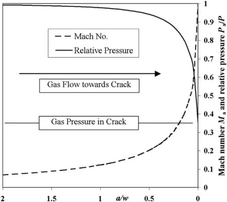
Now,evaluating both Maand subsequently Pafor 0<a/w<2,it can be seen in Fig.2 that Maincreases rapidly and Padecreases rapidly as the gas approaches the crack.Based on a numerical integration,the loss of drive pressure is equivalent to losing the full internal pressure P over a width only equal to 0.1w each side of the crack.
The significance of this prediction for casing drive modification is that the drive loss to the casing will be solely dependent on the crack width and the pressure P(R)inside the stagnant surface.Therefore,the casing drive loss is predicted to be almost independent of the actual amount of gas lost.

Fig.2.Rise in gas Mach number Maand fall in pressure on the inside casing surface,relative to the instantaneous remaining internal bulk pressure,with decreasing gas distance from the crack,expressed as a fraction a of the instantaneous crack width w.
5.Worked examples
In experiments at AWE Foulness[6],significant case fragment acceleration was observed post-fracture to very close to ideal Gurney velocity.Therefore,their experimental configuration will be used as the basis for iterative spreadsheet calculations(and later hydro-code modelling)so that comparisons may be made with their data.
First,for completeness,the buffer region of compressed air mixed with escaped explosive gases between the casing and the air shock must be considered.From Eq.(3.26)in Ref.[7],the pressure Pbuffin this buffer region just outside the casing envelope can be approximated by:

where Pairis the ambient air pressure(about 0.1 MPa);and Mairis the Mach number of the casing velocity in ambient air,for which γ=1.4.The casing radial velocity can be estimated from Gurney’s equation in Ref[4],where M is the casing mass and C the charge mass:

so that,if the sound velocity in air is denoted by aair,

for detonation velocity D ~8 km/s and aair~0.33 km/s.From Eq.(18),the pressure Pbuffof the air compressed ahead of the expanding casing is:

For example,if M/C=1,then Mairis 6.4 and Pbuffis 37Pairor about 3.7 MPa.At some point,Pbuffwill affect the optimum mass flow gas pressure in the crack Pc,forcing the gas to flow at higher pressures and lower rates.Since Pbuffonly becomes significant at very late times and also opposes case fragment acceleration,its net effect is small.
In the following spreadsheet calculations,only an approximate treatment will be made based simply on a suitable exponential function of P-Pbuff,the loss of gas drive pressure,relative to the accumulation of external gas/air pressure,which leads to a gradual tapering-off of the gas losses.
6.Iterative spreadsheet calculations
The analytical gas-flow calculations can only provide the gas escape rate at any one point in the casing expansion.Therefore,a spreadsheet was constructed,which could take the gas loss from one increment in system radial expansion and apply that to the succeeding increment.
In this approach,all the variables in Eq.(10)are calculated explicitly before the gas mass loss and internal pressure loss are calculated at each 5%step in expansion ratio.Comparison can also be made with the ideal instantaneous rate of radial acceleration of a casing which does not fracture.The ideal instantaneous rate can be calculated from the differential with respect to time t of the following equation from Ref.[1]for the intermediate Gurney velocity of the casing at any cylindrical expansion ratio:

This differentiation leads to the result:

Eq.(21)is needed by the spreadsheet to enable it to modify the casing acceleration in the spreadsheet according to gas mass lost and localised casing inner surface depressurisation.
Replicating the conditions in the pipe bomb experiments at AWE Foulness[6],the values for the key parameters would be ρ0=1500 kg/m3,R0=40 mm and Rf=84 mm.Also,in Ref.[6],the quoted detonation velocity for the RDX/wax 88/12 composition was D=8.03 km/s,from which the idealised constant volume burn pressure and Gurney energy(see Ref.[6])would be P0=10.74 GPa and E=P0/2ρ0=3.58 MJ/kg.
The casing thickness was varied from 1/8 inch(3.18 mm)to 3/4 inch(19.02 mm),so the Gurney M/C values ranged from 0.85 to 6.1.
The spreadsheet results illustrate very well the restrictions faced by the gases as they attempt to escape through the cracks.Immediately following casing fracture,the gases still have significant pressure,but the cracks are still small.By the time the cracks have enlarged,the gas pressure has dropped significantly,but then there is only a brief remaining window of opportunity(see Fig.3)allowing limited gas escape.At late time,the cracks are wide,but the driving pressure for gas escape is,by that point,very low.

Fig.3.Gas loss cumulated from a 3/4 inch(19.02 mm)steel Foulness-type pipe bomb casing fractured at 110%strain together with gas fraction lost in each casing expansion interval 0.05R0.
Furthermore,the escaped gases encounter the air shock which has been expanding radially ahead of the casing and have been building up behind it,creating a pressure,to which that inside the fractured casing envelope will eventually fall.
Based on Eq.(10)and the following numerical integration,the calculated loss of casing fragment velocity,due to internal depressurisation arising from gas escape,in this example,is much less than 1%.This is consistent with the experimental observation,in Ref.[6],of significant post-fracture radial acceleration.Furthermore,as pointed out above,the loss of casing acceleration is independent of the actual degree of gas loss.
7.Hydro-code modelling
An assumption basic to the simplified analytical approach was that phenomena are quasi-steady state,i.e.wave phenomena internal to the casing are assumed by the time of casing fracture to have subsided.Therefore,the results of modelling the same problem in the CTH hydro-code,where wave phenomena are included,will also be shown.
Modelling was done in 2D in the Eulerian code CTH[8].The example modelled was one of the cylindrical charges fired by Denny,et al.[6]which had the thinnest(1/8th inch)steel casing.A model was not available in CTH for the RDX-wax composition fired in 1970,so explosive C-4,which is slightly more energetic,was modelled as the nearest available equivalent.
Symmetry was utilised to reduce the size of the problem with the x=0 and y=0 axes treated as perfectly reflective boundaries,while material was allowed to flow out of the simulation at the x=15.0 cm and y=15.0 cm boundaries.A regular 0.1 mm mesh was used during the course of the simulations.Air at 101.325 kPa was used to fill the simulation box that was not otherwise occupied.
Simulations were run between 45 and 50μs,by which time explosive products had started to leak out between the gaps in the case.The Mie-Gruneisen Equation of State Elastic-Perfectly Plastic Model and Johnson-Cook Damage Model[10]were employed in the simulation of the steel and the material parameters can be found in Ref.[9].The JWL Equation of State was used for the C4 explosive and products,and the model parameters can be found in Ref.[11].The Sesame tabulated Equation of State was used for air with the model parameters found in Ref.[12].
Marker particles that followed the material in which they started were used to judge the speed of various parts of the casing and the velocity of gaseous materials passing through areas of the simulation.Marker particles that were spatially fixed were used to judge the fl ow of materials and development of pressure and density at specific points in simulation space.
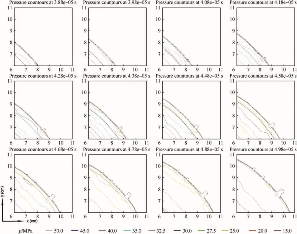
Of great interest in Fig.4 are the examples of the development of the contours of gas pressure variation as it flows towards a typical early opening in the casing.It can clearly be seen that,on top of the natural reduction in overall pressure inside the casing due to radial expansion,there is a localised decrease in pressure as the explosive products escape through the fractures.Particularly in frames timed at 41.8 and 44.8μs,the gas pressure contours internal to the crack are similar in form to those assumed in the analytical approach to exist between a crack and an inwardly surrounding stagnant surface.
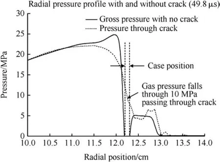
In all the later frames,escaping explosive products can clearly be seen.As can be seen in Fig.5,the pressure in the centre of the crack in the latest frame(at a time of 49.8μs after detonation)is approximately 10 MPa,compared to a pressure inside the fractured casing of around 22 MPa.This difference corresponds to a value of q,as defined above,of 0.45 for γ value of about 2.0 at high gas expansion.Also,once the crack has widened to several millimetres,the difference between the radial pressure profile with and without a crack is very apparent.

Fig.4.The change in pressure contours inside the casing during fracture.The expansion ratio ranges from 2.50(38.8μs)in the first frame to 3.05(49.8μs)in the final frame.T0is taken as the time of initiation of the explosive.The units for the x and y axes are ‘cm’and the origin is at the centre of the steel tube/explosive.

Fig.5.Typical radial gas pressure profiles through a crack and solid casing at 49.8μs.The sharp drop in the pressure profile through the casing around 12.25 cm is due to the case material registering almost zero internal pressure.
The pressure profile for gas approaching the crack is very similar in form to that calculated above and shown in Fig.2,confirming that the gas pressure rises rapidly away from the crack,minimising the extent of internal depressurisation.In both pressure profiles,a region of elevated pressure(~5 MPa)can be seen just outside the casing.This is the region behind the air shock which is being driven ahead of the expanding casing.In the profile through the crack,more wave features are visible due to explosive gases expanding rapidly into the air shock region.
Marker particles placed in a line normal to,and through the centre of,a crack were also used to record the predicted velocity of the gaseous explosive products as they expanded inside the casing and out through the crack.From the above analytical calculation,this was expected to be~540 m/s at the same expansion ratio.
It can be seen from Fig.6 that the peak velocity with a crack in place(Line B)is found just outside the casing and falls off extremely sharply at a radius of about 13 cm from the centre.The region between 12 cm and 13 cm from the centre exhibits the clearest difference between the fractured(Line B)and un-fractured(Line C)regions of the casing at 49.8μs.In this region,the velocity in advance of the crack is up to 1 km s-1faster than that in advance of the un-fractured casing,purely due to the supersonic escape of the gaseous explosive products.As the gas passes through the crack,its additional velocity,relative to the crack,is 250-300 m/s.This is about half the value found from the analytical calculation at the same expansion ratio.

Fig.6.The velocity profile normal to the casing through the casing and a crack at 37.5μs and 49.8μs.
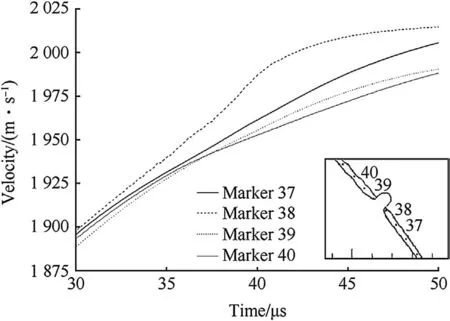
Marker particles were placed in the casing material to follow the velocity of the casing as it expanded and fractured.As can be seen from Fig.7,which shows the casing velocity variation with time for a range of marker particles in the casing at various distances from a crack,the CTH model does show that the casing continues to accelerate radially postfracture.

Fig.7.Predicted velocity of points in the casing as a nearby crack opens,from which acceleration of the case can be inferred.Insert shows the marker particle positions in the casing and the outlines of the materials,including the explosive products bursting out of the casing at 41.3μs in the calculation.
Also,looking at the velocities shown for the CTH marker particles 39 and 40 in Fig.7,these differ very little.This implies close correspondence with the conclusion from Section 4 that the residual gas drive pressure to the casing rises rapidly with distance from the crack,as shown in Fig.2.
8.Conclusions
While the two approaches described above to the problem of calculating gas escape through a fracturing bomb casing do not agree as to the exact magnitudes of the gas pressures,densities and fl ow rates,the values obtained by either approach support the same general conclusion.
As both the analytical approach and the hydro-code modelling have shown,while the internal gas pressure at casing fracture may be high,gas fl ow is limited by its own sound-speed and the initial narrowness of the cracks.As these widen,the gas fl ow rate increases,but the continued adiabatic expansion of the gases within the casing envelope competes with the widening of the cracks,so that the gas fl ow rate reaches a peak.The other main factor competing with the gas fl ow rate is the very rapid radial expansion of the casing,which very much curtails the time-window during gas escape.Furthermore,the gas fl ow passing over the fragments is eventually reduced and finally shut off by the external pressure of shock-compressed ambient air mixed with escaped gases that still surrounds the rapidly expanding fractured casing.
To quote again from Ref.[2],page 387:“The detonation gases will then stream around the fragments or bypass them,and the acceleration process stops there.…Typically,the fragment velocities of exploding spheres and cylinders of brittle metals are 80%of the predicted value.”
While there is experimental evidence for the second part in Ref.[2]that the final fragment velocities from harder metal casings are lower than that would be predicted by the Gurney model,both our calculations and the continuing radial expansion described in Ref.[6]indicate that the cause of this is not prompt gas escape.Another explanation for reduced fragment velocity may need to be sought among the further interactions that take place between the separated casing fragments and the blast wave during the interval following the establishment of energy equilibrium and before the fragments escape from the blast wave.
A repetition of the experiments in Ref.[6],but with the laser and radar velocimetry techniques developed in the intervening forty years,could prove decisive on this issue.
Acknowledgements
This work was sponsored by the NWIPT Department of the U.K.Ministry of Defence.
[1]Hutchinson MD.Replacing the equations of Fano and Fisher for cased charge blast impulse-II-fracture strain method.Propellants Explos Pyrotech 2012;37:605-8.
[2]Cooper PW.Explosives engineering.New York:Wiley-Blackwell;1996.Chapter 27.
[3]Anderson Jr JD.Modern compressible flow-with historical.New York:McGraw-Hill;1982.
[4]Gurney RW.The initial velocities of fragments from bombs,shells and grenades;1943.U.S.Ballistics Research Laboratories Report 405.
[5]Hutchinson MD.Replacing the equations of Fano and Fisher for cased charge blast impulse-III-yield stress method.Propellants Explos Pyrotech August 2014;39(4).http://dx.doi.org/10.1002/prep.201300173.
[6]Denny PH,James DJ,James HR.Blast and fragments from steel cylinders containing RDX/wax explosive with varying aluminium content,part 2:the initial velocity of the casing.AWRE Report No.040/70;1970.
[7]Kinney GF.Explosive shocks in air.New York:Macmillan;1962.
[8]McGlaun JM,Thompson SL,Elrick MG.CTH:a three-dimensional shock wave physics code.Int.J.Impact Eng.1990;10:351-60.CTH v10.0.Sandia Corporation,Albuquerque,NM,USA,.
[9]Group GMX-6.Selected Hugoniots.LA-4167-MS.NM,USA:Los Alamos National Laboratory;1969.
[10]Johnson GR,Cook WH.Fracture characteristics of three metals subjected to various strains,strain rates,temperatures,and pressures.J Eng Fract Mech 1985;1:31-48.
[11]Dobratz BM,Crawford PC.LLNL explosives handbook:properties of chemical explosives and explosive simulants.Report UCRL-5299-Rev.2.CA,USA:University of California,Lawrence Livermore National Laboratory;1985.
[12]Kerley GI,Christian-Frear TL.Sandia report.SAND93-1206-UC-705.Albuquerque,NM,USA:Sandia National Laboratories;1993.
- Defence Technology的其它文章
- Shock tube design for high intensity blast waves for laboratory testing of armor and combat materiel
- Long-rod penetration:the transition zone between rigid and hydrodynamic penetration modes
- Damage visualization and deformation measurement in glass laminates during projectile penetration
- Reduction of global effects on vehicles after IED detonations
- Numerical simulation of the natural fragmentation of explosively loaded thick walled cylinders
- Study of simple plane wave generator with an air-metal barrier

