Second-order Sliding Mode Control of DFIG Based Variable Speed Wind Turbine for Maximum Power Point Tracking
Xiangjie Liu Chengcheng Wang Yaozhen Han,2
Second-order Sliding Mode Control of DFIG Based Variable Speed Wind Turbine for Maximum Power Point Tracking
Xiangjie Liu1Chengcheng Wang1Yaozhen Han1,2
This paper proposes a super-twisting second order sliding mode control scheme to maximize the wind energy capture of a doubly fed induction generator based variable speed wind turbine(VSWT)system,and minimize the reactive power simultaneously.Two second order sliding mode controllers are designed to achieve the control objectives,reduce mechanical stress and improve control accuracy.By regulating the generator rotor voltage,one controller makes the wind turbine rotor speed track the optimal speed,which can maximize power generation.The other maintains the rotor current at rated value to minimize the reactive power.A quadratic form Lyapunov function is adopted to determine the range of controller parameters and guarantee the fi nite time stability.Simulation results on a 1.5MW doubly fed induction generator(DFIG)-based variable speed wind turbine demonstrate the validity of the proposed control strategy.
Doubly fed induction generator(DFIG),maximum power point tracking(MPPT),second order sliding mode(SOSM)control,variable speed wind turbine(VSWT)
DOI10.16383/j.aas.2017.e150252
1 Introduction
Recent years wind energy conversion systems have advanced rapidly,due to the increasing concern for the environment pollution caused by the traditional energy sources.Through tracking the changing wind speed by adjusting the shaft speed,the variable speed wind turbines(VSWTs)enable the turbine to operate at its maximum power coefficient over a wide range of wind speeds[1].To achieve the major task of power efficiency maximization,the VSWT should track the maximum power point despite wind variations[2].
Originally,the VSWT control system is designed based on the linear system theory[3]?[5].The linear control encountered difficulties since VSWT system is a complex and highly nonlinear system with strong coupling features and uncertainty in both the aerodynamics and the electrical parts.To account for the nonlinear behavior,and to deal with the recognized problem of parameter variations,various advanced control strategies have been proposed,such as neural networks[6],adaptive control[7],feedback linearization technique[8],predictive control[9]and sliding mode approach[10]?[11].Among these control strategies,sliding mode control(SMC)has proven to be very robust with respect to system parameter variations and external disturbances,and thus suitable for realizing VSWT system control.However,the standard fi rst-order sliding mode(FOSM)control generally shows signi fi cant drawback of chattering phenomenon.Some key components in the wind turbine(WT),such as gear box,would get damaged by the abrupt commutation in forces and torques[12].
Instead of in fl uencing the fi rst order time derivative of sliding variable,the second-order sliding mode(SOSM)control acts on the second order derivatives of the slid-ing surfaces,which can help reduce the chattering phenomenon and provide higher sliding precision.Particularly,the SOSM super-twisting algorithm has been an e ff ective way of controlling the VSWT system,since it only requires measurement of the sliding variable without using information about derivatives of the sliding constraint.A number of contributions on this control strategy have recently appeared for the realization of maximum power point tracking(MPPT)of VSWT system.Valenciaga et al.[13]obtained the control objective of wind energy conversion optimization of brushless doubly fed reluctance machine(BDFRM)based VSWT.Beltran et al.[14]presented a SOSM controller that facilitates the generator torque tracking the optimal torque,and maximized the power extraction of doubly fed induction generator(DFIG)based VSWT.Evangelista et al.[15]synthesized a super-twisting sliding mode control with variable gain,and showed a better performance in terms of mechanical loads and power tracking.However,in the aforementioned literatures,the SOSM control mainly concentrated on the electrical side dynamic control.For achieving the control objective of maximum power extraction,the generator torque was set to track the optimal aerodynamic torque,and it means that the energy loss caused by friction and mechanical rotational inertia in the transmission system was neglected in such circumstance.In other words,the captured power from wind was assumed to be equal to generator output power.This assumption is not always consistent with the actual situation,especially in turbulent wind scenarios.
Therefore,this paper aims to investigate a new SOSM control method for the DFIG based VSWT system.A complete dynamic model of the VSWT system is established by integrating both aerodynamic and electrical parts,together with parameter uncertainties and perturbations.The control objective is to make the wind turbine rotor speed track the desired speed(the speed that is given by a MPPT)in spite of system uncertainties,and maintain the rotor current at rated value which can minimize the reactive power.This control strategy can provide a faster control action as the wind speed variations can be re fl ected instantaneously and signi fi cantly on the rotor speed reference signal,andyield more energy.Besides,by adopting quadratic Lyapunov function[16],the range of control parameters is obtained to guarantee the fi nite time convergence of the SOSM control system.
The article is organized as follows.The modeling of the VSWT system is presented in Section 2.Section 3 explains the problem formulation and the detailed control strategy.The comparative simulation results for the 1.5MW threeblade DFIG-based WT system are investigated in Section 4.Finally,the conclusion is stated in Section 5.
2 VSWT System Modeling
The VSWT system is mainly composed of a turbine,a gearbox,and a generator,which are combined to convert wind energy into electric energy.According to di ff erent wind speeds,the VSWT system works at four di ff erent operating regions,as shown in Fig.1.While the wind speed is below the cut-in speed vcutin,the produced torque is insufficient to drive the turbine,thus it cannot realize the startup function.While the wind speed increases over the cut-in speed vcutinand below the rated speed vrated,the VSWT system tries to capture the maximum wind energy by adjusting the rotor speed of WT.This region is called the partial load region.With the increasing wind speed satisfying vrated<v<vcutoff,the WT tries to maintain the rated output power by regulating the pitch angle,called the full load region.There is an additional region,called the shutdown region,where the turbine stops operation due to high wind speed.

Fig.1.WT operation regions.
Obviously,the control task in the partial load region is more challenging,since the dynamics in this region is quite complex.Thus the study in this paper concentrates on the modeling and control in this region.The mathematical model in this region consists of formulas accounting for the electrical dynamics of the rotor and the dynamics of the mechanical rotational speed,including also the damping and resistance uncertainties caused by long-term mechanical wear and ambient temperature changes[8],[14].It is expressed as:
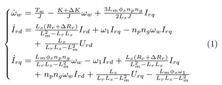
where ΔK and ΔRrrepresent the parameter uncertainties of the damping and resistance respectively,and the constraints|ΔK|≤ 0.5K and|ΔRr|≤ 0.5Rrare satis fi ed.The other symbols in(1)are described as:
ωwwind turbine rotor speed;
Irdthe d-axis component of rotor current;
Irqthe q-axis component of rotor current;
Urdthe d-axis component of the rotor voltage;
Urqthe q-axis component of the rotor voltage;
J the inertia of the combined rotating parts;
K turbine total external damping;
nggearbox ratio;
φsstator fl ux;
Lmmutual inductance;
Lsstator leakage inductance;
Lrrotor leakage inductance;
Rrrotor resistance;
ω1synchronous speed;
nppole pair number.
In order to concisely express(1),de fi ne
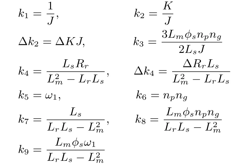
this leads to

The VSWT system model(2)is composed of two parts,e.g.,the turbine model and the DFIG model.The single mass model of the turbine is[8]:

where Twis the aerodynamic torque and Temis the generator electromagnetic torque.
The nonlinear characteristics of Twis established based on the aerodynamic principles[14],e.g.,

where Pwis the aerodynamic power and Cp(λ,β)is the power coefficient relating to a nonlinear function a ff ected by the blade pitch angle β and the tip-speed ratio λ,de fi ned as

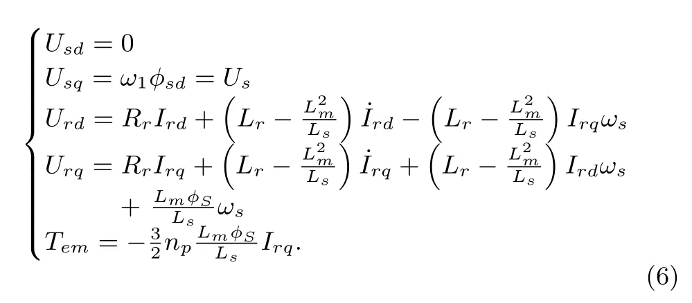
The DFIG model in the synchronously rotating frame dq is established as(6)based on the stator fl ux orientation,whose phase diagram is shown in Fig.2.
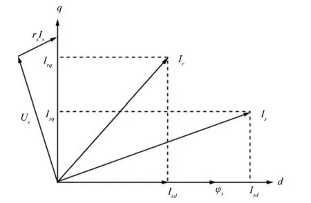
Fig.2. Phase diagram of stator fl ux orientation.
3 The VSWT System Control Strategy
3.1 Problem Formulation
Considering(4)and(5)in Section 2,the aerodynamic power that can be captured by a wind turbine is:

As the main control objective of the above VSWT system in the partial load region is to track the maximum power point and harvest more wind energy,the power conversion coefficient Cp(λ,β)must reach the maximum value Cpmaxin various wind speeds.
Cp(λ,β)is generally expressed as[17]:

with 1/Λ =1/(λ+0.08β)? 0.035/(β3+1).The coefficients c1?c6depend on the WT design characteristics.And the following coefficient values are adopted in this work:c1=0.5176,c2=116,c3=0.4,c4=5,c5=21,c6=0.0068.
Actually,in the partial load region,the pitch angle β is fi xed at zero,to achieve the maximum power conversion coefficient Cpmax[2].Then the Cp?λ characteristic with a constant pitch angle β =0°is shown in Fig.3.The tipspeed ratio λ must be maintained at an optimal point for achieving the maximum power coefficient Cpmax.
Considering Fig.3 and the de fi nition of λ in(5),it is thus necessary to adjust the rotor speed ωwaccording to the wind speed variation in the partial load region,to maintain the tip-speed ratio λ at an optimal point λopt.This could guarantee the maximum power coefficient Cpmax,and from(7),when Cpis controlled at the maximum value,maximum output power Pamaxis extracted from wind.Thus,the optimal WT rotor speed ωoptis given by:


Fig.3. Cp-λ characteristic of wind turbine.
In the DFIG based VSWT system(2),this maximum wind energy capture objective can be achieved by means of the rotor voltage regulation in the generator.The rotor voltage can also control the rotor current Ird,and thus regulate the stator-side reactive power Qs,which can be expressed as:

Thus the designed SOSM control system should accomplish two major objectives.One is to maximize power extraction,by controlling the rotor speed to track the optimal rotor speed ωopt,which is regulated by q-axis component of generator rotor voltage.The other is to minimize the reactive power by controlling Irdto follow an external reference,which is regulated by d-axis component of generator rotor voltage.
Here,Qsis set to zero to ensure a unity power factor operation of the studied VSWT system which renders the rotor reference current Irdras

3.2 SOSM Controller Design
In order to achieve the control objectives in the partial load region,the nonlinear SMC scheme is presented in this section.The schematic diagram of the DFIG-based WT system is shown in Fig.4.
In designing a general SMC for the VSWT system,the tracking error between the actual rotor speed and the desired value ωopt,and also the error between the actual and the desired d-axis component of rotor current,are de fi ned as:

Then the sliding variables are de fi ned as follows:

where c>0.

Respecting the VSWT system model(2),the fi rst-order derivatives of sliding variables are
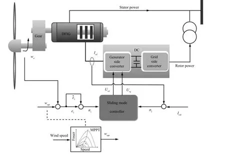
Fig.4.The schematic diagram of the DFIG-based WT system.
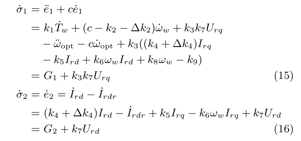
where G1and G2contains the state variables,VSWT parameters and parameter perturbations:

Using the standard SMC with the approaching law method[18],the so-called exponential approaching law is selected as

where σ is the sliding variable, ε and δ are the designed parameters.
Then the dq-axis components of rotor voltages are deduced as

Since the switching term εsgn(σ)acts on the controller directly,it makes the control inputs Urdand Urqdiscontinuous and leads to intensive chattering e ff ect.
Using the super-twisting algorithm[19],the control inputs Urdand Urqare reconstructed as
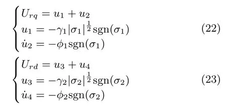
where γ1,φ1,γ2,φ2are undetermined control parameters.
Notice that the discontinuity of super-twisting SOSM control appears only in its derivative term,such that the control inputs Urdand Urqin system(2)are actually continuous.Namely,the SOSM reduces the chattering e ff ect while preserving all the advantages of standard SMC.
By using this SOSM scheme,it is very important to choose suitable control parameters for stable operation of WT system.Here a Lyapunov method is employed to determine the range of control parameters,and then guarantee stable operation of the WT system.
In order to ensure σ1→0,→0 in fi nite time,which means achieving a precise tracking of optimal rotor speed,the ranges of γ1and φ1are needed to be addressed.Firstly,a state transformation is introduced as

and taking into consideration(22),then,(15)is deduced as

As shown in(17),the perturbation G1is di ff erentiable,and its fi rst-order derivative is uniformly bounded,such that it satis fi es

where Π1is a positive constant.
Now,choose the quadratic Lyapunov function

Setting the matrix C=[1 0],the derivative of the Lyapunov function along the trajectories of the perturbed system(25)is deduced as
Choose Q=?(ATP+PA+Π21CTC+PBBTP),then


When Q is a symmetric and positive de fi nite matrix,there exists,which satis fi es the Lyapunov theorem.Then the control system will converge to origin in fi nite time[16].
The matrix Q is given as(31),see the bottom of this page.
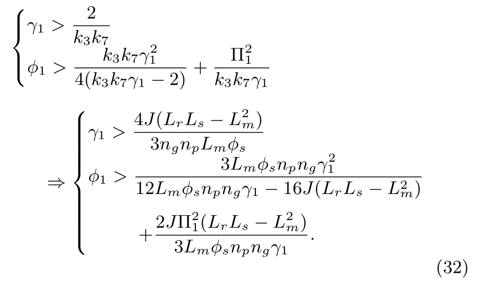
Set Q to be a positive de fi nite matrix,and for fi nite time convergence characteristics the ranges of γ1and φ1must be satis fi ed with
Similarly,the perturbation G2is di ff erentiable as shown in(18),and its fi rst-order derivative is uniformly bounded,so that it satis fi es

The ranges of γ2and φ2,which ensure σ2→0,˙σ2→0 in fi nite time,are deduced as
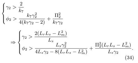
As long as the control parameters γ1,φ1,γ2and φ2fall into the range of(32)and(34),the whole DFIG-based WT system may operate steadily.
4 Simulation Results
The proposed SOSM was simulated on a 1.5MW WT system.The system parameters based on a 1.5MW wind turbine are shown in Table I[14].The parameter perturbations of resistances ΔK and the turbine damping ΔRrin Δk2and Δk4,are taken into account as ±20%of their nominal values and shown in Table I.The simulation step size is set as 0.001s.In designing the SOSM controller forWT system,the parameters are deliberately chosen according to the conditions(32)and(34),together with a thorough analysis and comprehensive computer simulation,to guarantee its fi nite time stability.Finally,these parameters are chosen as φ1=20,γ1=1 ×10⁵,φ2=0.03,γ2=1000.
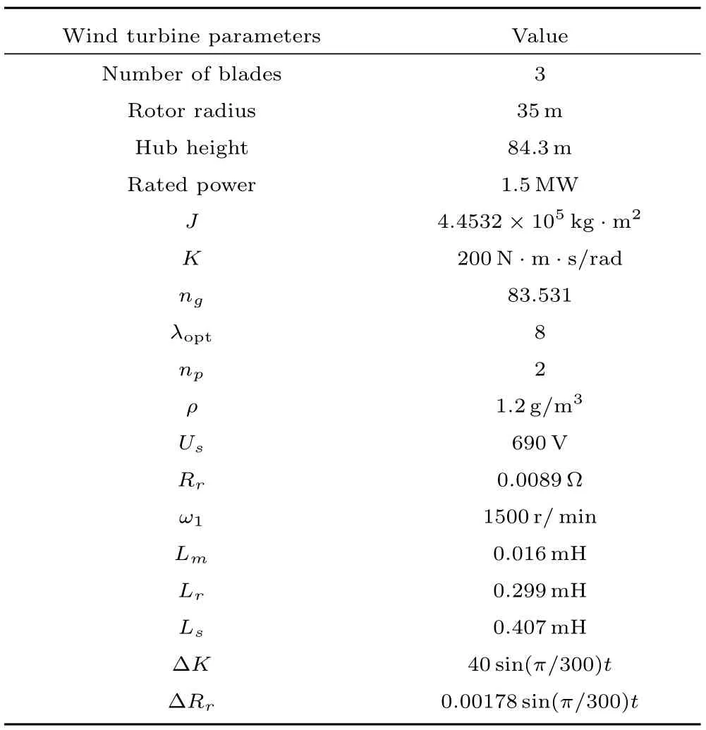
TABLE I CHARACtERistiC oF tHE SiMuLAtED WiND TuRBiNE SystEM
In order to verify the control e ff ect under di ff erent operating environment,two case studies are considered in this section.Case 1 uses a stepwise-varying wind speed to test the validity of the proposed SOSM control strategy under a sudden wind change.A PID control and a standard fi rst order sliding mode(FOSM)control are also constituted in this case,to show the robustness and chattering-free behavior of the SOSM controller.The e ff ectiveness has been further demonstrated using the turbulent wind speed in Case 2,to test validity of the proposed SOSM control strategy under realistic VSWT conditions.
Generally,the cut-in wind speed of 1.5MW WT is 3m/s,the cut-out wind speed is 25m/s,and the rated wind speed is in the range of 11m/s to 13m/s.Therefore,in these simulations,the wind speed varies within the range between 3m/s and 12m/s,making the WT system operates in the partial load region.Two case studies are described as follows.
4.1 Case 1:Stepwise Wind Speed
In order to show the controller performances under a sudden wind change,the fast step variations of the wind speed are used in this simulation,as shown in Fig.5.For comparing purpose,a PID control and a FOSM control are also constituted.The PID control parameters are chosen as kp1=1.2,ki1=0.08,kd1=0.07;kp2=6.9,ki2=20.6,kd2=7.6,and the FOSM control parameters are ε1=5,δ1=100;ε2=3,δ2=10.
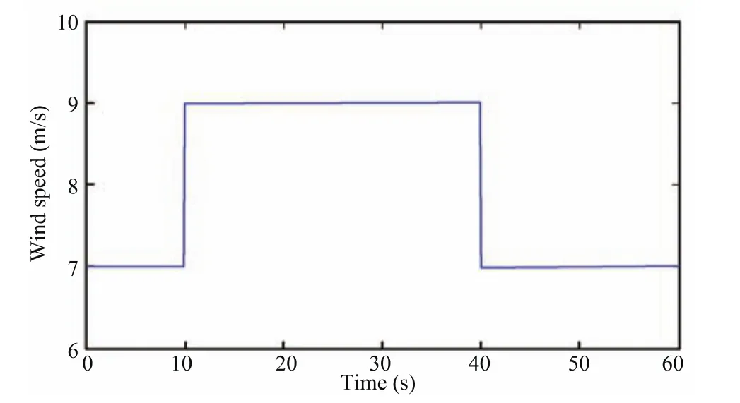
Fig.5. Stepwise wind speed pro fi le.
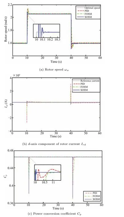
Fig.6.Regulation performances of ωw,Irdand Cp.
Fig.6 shows the regulation performances of the wind turbine rotor speed ωw,the generator rotor current Irdand the power coefficient Cp.It can be observed from Fig.6(a)that all the three controllers can make the rotor speed track the optimal speed under the same wind speed variation.How-ever,the tracking accuracy of the rotor speed with the proposed SOSM control strategy is higher,and the response time is shorter.The resulting generator d-axis rotor current Irdshown in Fig.6(b)demonstrates that the PID control scheme is not robust for parameter uncertainties.Since the wind turbine rotor speed can track its optimal value tightly,the power coefficient Cpwill reach its maximum value Cpmax.As shown in Fig.6(c),the SOSM control strategy gives a faster response during sudden change of the wind speed,and makes the Cprecover to Cpmaxin 0.2s after the sudden drop,yielding the maximum aerodynamic power.
The actual controller output Urdand Urqare shown in Fig.7.The switching term ε ·sgn(σ)appears directly in control input(20)and(21)for the FOSM controller,while the discontinuity in the SOSM controller(22)and(23)is hidden in their derivative term.Therefore,as is shown in Fig.7,the chattering phenomenon,which is rather serious under FOSM method,is almost eliminated under the proposed SOSM control strategy.Actually,smooth Urdand Urqcan reduce the mechanical stress on the VSWT system.
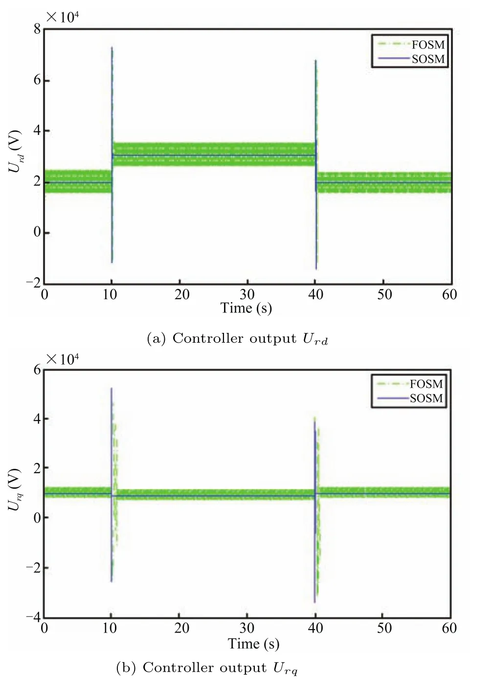
Fig.7.Comparison of the FOSM and the SOSM controller outputs.
4.2 Case 2:Randomly Varying Wind Speed
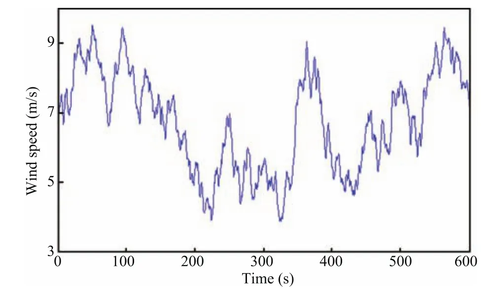
Fig.8. Randomly varying wind speed pro fi le.

Fig.9. Regulation performances of ωw,Irdand Cp.
In order to evaluate the tracking performance,robustness and chattering-free behavior of the proposed SOSM control strategy under realistic VSWT conditions,a 10-min randomly varying wind speed is adopted in the simulation.As shown in Fig.8,the wind speed is ranging between 3m/s and 10m/s.The evolution of the rotor speed and the optimal speed is depicted in Fig.9(a).Compared with thePID controller,the SOSM controller features more accurate and faster response in rotor speed tracking.Irdis shown in Fig.9(b).The result shows that,the SOSM controller is robust for the internal disturbances and external disturbances,which are caused by parameter uncertainties and wind speed fl uctuations respectively.And this yields a very good tracking performance of rotor current.Fig.9(c)shows the power conversion coefficient,since the SOSM control strategy gives an accurate tracking of the optimal rotor speed,the Cpsuccessfully maintains at Cpmax,which yields the maximum aerodynamic power.The three simulation results in Fig.10 indicate that the control objectives of maximum power point tracking and minimized stator reactive power are achieved e ff ectively.
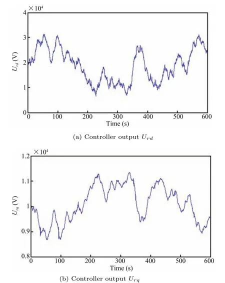
Fig.10.SOSM controller outputs.
The evolution of the SOSM controller output Urdand Urqare shown in Fig.10.As can be seen from the fi gures,the SOSM controller does not cause any intense chattering,and the smooth features determined by the use of SOSM control strategy will reduce the mechanical stress on the system.
5 Conclusion
In this paper,a new SOSM control approach for DFIG-based VSWT system is proposed to achieve the objectives of maximum power point tracking and minimum stator reactive power.The two SOSM controllers are designed based on the super-twisting algorithm,which only require measurement of the sliding variables without using information about the time derivatives of the sliding constraint.Quadratic form Lyapunov function method is employed to choose controller parameters,and guarantee the fi nite time stabilization of closed-loop system.The controllers are simulated based on a complete model of the DFIG-based VSWT,which includes both the mechanical and the electric dynamics,together with parameter uncertainties and perturbations.A PID control method and a standard SMC are also carried out for comparison.The simulation results indicate that the proposed control strategy is rather suitable for controlling the DFIG-based VSWT system,and the control objectives are successfully achieved in both step wise-varying wind speed and a randomly varying turbulent wind speed.Compared with the PID controller and conventional fi rst-order SMC,the proposed control strategy shows a higher robustness,and the chattering phenomenon of rotor control voltage is almost eliminated.
1 C.Ming and Z.Ying,“The state of the art of wind energy conversion systems and technologies:A review,”Energy Convers.Manage.,vol.88,pp.332?347,Dec.2014.
2 M.L.Corradini,G.Ippoliti,and G.Orlando,“Fully sensorless robust control of variable-speed wind turbines for efficiency maximization,”Automatica,vol.49,no.10,pp.3023?3031,Oct.2013.
3 F.Poitiers,T.Bouaouiche,and M.Machmoum,“Advanced control of a doubly-fed induction generator for wind energy conversion,”Electric Power Syst.Res.,vol.79,no.7,pp.1085?1096,Jul.2009.
4 J.S.Wang,N.Tse,and Z.W.Gao,“Synthesis on PI-based pitch controller of large wind turbines generator,”Energy Convers.Manage.,vol.52,no.2,pp.1288?1294,Feb.2011.
5 I.Munteanu,N.A.Cutululis,A.I.Bratcu,and E.Ceangˇa,“Optimization of variable speed wind power systems based on a LQG approach,”Control Eng.Pract.,vol.13,no.7,pp.903?912,Jul.2005.
6 H.Chitsaz,N.Amjady,and H.Zareipour,“Wind power forecast using wavelet neural network trained by improved Clonal selection algorithm,”Energy Convers.Manage.,vol.89,pp.588?598,Jan.2015.
7 S.Abdeddaim,A.Betka,S.Drid,and M.Becherif,“Implementation of MRAC controller of a DFIG based variable speed grid connected wind turbine,”Energy Convers.Manage.,vol.79,pp.281?288,Mar.2014.
8 B.Boukhezzar and H.Siguerdidjane,“Nonlinear control with wind estimation of a DFIG variable speed wind turbine for power capture optimization,”Energy Convers.Manage.,vol.50,no.4,pp.885?892,Apr.2009.
9 X.B.Kong and X.J.Liu,“Nonlinear model predictive control for DFIG-based wind power generation,”Acta Automat.Sin.,vol.39,no.5,pp.636?643,May 2013.
10 Z.Y.Chen,M.H.Yin,C.X.Cai,B.Y.Zhang,and Y.Zou,“An accelerated optimal torque control of wind turbines for maximum power point tracking,”Acta Automat.Sin.,vol.41,no.12,pp.2047?2057,Dec.2015.
11 B.Beltran,T.Ahmed-Ali,and M.El Hachemi Benbouzid,“Sliding mode power control of variable-speed wind energy conversion systems,”IEEE Trans.Energy Convers.,vol.23,no.2,pp.551?558,Jun.2008.
12 G.Bartolini,A.Ferrara,and E.Usai,“Chattering avoidance by second-order sliding mode control,”IEEE Trans.Automat.Control,vol.43,no.2,pp.241?246,Feb.1998.
13 F.Valenciaga and C.A.Evangelista,“2-Sliding active and reactive power control of a wind energy conversion system,”IET Control Theory Appl.,vol.4,no.11,pp.2479?2490,Nov.2010.
14 B Beltran,M El Hachemi Benbouzid,and T Ahmed-Ali,“Second-order sliding mode control of a doubly fed induction generator driven wind turbine,”IEEE Trans.Energy Convers.,vol.27,no.2,pp.261?269,Jun.2012.
15 C.Evangelista,F.Valenciaga,and P.Puleston,“Active and reactive power control for wind turbine based on a MIMO 2-sliding mode algorithm with variable gains,”IEEE Trans.Energy Convers.,vol.28,no.3,682?689,Sep.2013.
16 J.A.Moreno and M.Osorio,“Strict Lyapunov functions for the super-twisting algorithm,”IEEE Trans.Autom.Control,vol.57,no.4,pp.1035?1040,Apr.2012.
17 J.Zaragoza,J.Pou,A.Arias,C.Spiteri,E.Robles,and S.Ceballos,“Study and experimental veri fi cation of control tuning strategies in a variable speed wind energy conversion system,” Renew.Energy,vol.36,no.5,pp.1421?1430,May 2011.
18 W.B.Gao,Variable Structure Control Theory.Beijing,China:China Science and Technology Press,1990.
19 A.Levant,“Sliding order and sliding accuracy in sliding mode control,” Int.J.Control,vol.58,no.6,pp.1247?1263,Dec.1993.
He subsequently held a postdoctoral position with the China Electric Power Research Institute(CEPRI),Beijing,China,until 1999.He has been an Associate Professor in CEPRI since 1999. He was a Research Associate with the University of Hong Kong,and a Professor with National University of Mexico.He is now a Professor with the Department of Automation,North China Electric Power University,Beijing,China.His research interests include fuzzy control,neural networks,model predictive control with its application in industrial processes.
Prof.Liu is a member of Technical Committee on Control Theory,a member of Technical Committee on Process Control,Chinese Association of Automation,an editor of Chinese Journal of Control Engineering and an editor of Chinese Journal of Electric Power Automation Equipment.He has been in Program for New Century Excellent Talents in University since 2006.
E-mail:liuxj@ncepu.edu.cn

ChengchengWang is a master student in the Department of Automation,North China Electric Power University(NCEPU).She received the B.S.degree in automation in 2008,from Department of Automation,NCEPU.Her main research interest is sliding mode control of wind turbine systems.
E-mail:wangcc@ncepu.edu.cn

Yanzhen Han received the B.S.degree in automation in 2005 from Qingdao University of Science and Technology,Qingdao,China,and the M.S.degree in automatic control in 2008,from Shandong University,Jinan,China.He is currently working toward the Ph.D.degree in automatic control at North China Electric Power University,Beijing,China. Now he also works as an Associate Professor in Shandong Jiaotong University,Jinan,China.His research interests include modeling,optimization,and sliding mode control of power plants.Corresponding author of this paper.E-mail:hyz125@163.com
Xiangjie Liu,Chengcheng Wang,and Yaozhen Han.Second-order sliding mode control of DFIG based variable speed wind turbine for maximum power point tracking.Acta Automatica Sinica,2017,43(8):1434?1442
the Ph.D.degree in electrical and electronic engineering from the Research Center of Automation,Northeastern University,Shenyang,China,in 1997.
Manuscript
October 15,2015;accepted February 28,2016.
This work was supported by the National Natural Science Foundation of China(61273144),and Natural Science Foundation of Beijing(4122071).
Recommended by Associate Editor Qinmin Yang.
1.State Key Laboratory of Alternate Electrical Power System with Renewable Energy Sources,North China Electric Power University,Beijing 102206,China 2.School of Information Science and Electrical Engineering,Shandong Jiaotong University,Jinan 250357,China.

