Numerical investigation on flow and heat transfer characteristics of corrugated tubes with non-uniform corrugation in turbulent flow
Dongwei Zhang ,Hanzhong Tao ,*,Yuan Xu ,Zishuai Sun
1 College of energy science and engineering,Nanjing Tech University,Nanjing 211816,China
2 The Corporation of Towngas,Changzhou 213000,China
1.Introduction
Shell-and-tube and double-pipe heat exchangers are used in various industry fields and the heat-exchange tubes are the core components of them.In order to reduce the energy consumption and increase the economic benefit,high-efficiency heat exchange units in the thermodynamic process are becoming more and more vital for many applications.Hydrodynamically and thermally fully developed turbulent flow in tubes is common in many industrial applications,which has been extensively investigated before.As to the heat-exchange tube,roughness enhancement method is one of the most effective way to improve the heat transfer performance although with the increase of pressure drop at developed turbulent flow condition.Nowadays,the corrugated tubes have been widely used in single-phase flow of commercial applications because of its low-cost manufacturing and large enhancement of heat transfer[1].The characteristics of pressure drop and heat transfer in laminar,transition and turbulent flow of the corrugated tube have been widely investigated in the past few decades.
Many researchers have made a lot of experimental studies on the corrugated tubes.For example:Vicente et al.[1–3]experimentally investigated the heat transfer,pressure drop and friction factor of single-phase flow in the corrugated tube covered the Reynolds number ranging from 100 to 90000.Olivier[4]and Rainieri et al.[5]investigated the heat transfer performance of the smooth and corrugated tubes in laminar and transitional flow condition based on experiment method.However,there are also some researchers[6,7]who have attempted to study the corrugated tubes with numerical simulation method.For example:based on direct numerical simulation method,Piller[6]investigated the turbulent forced convection in a pipe with three different wall thermal conditions.Meanwhile,the separation characteristics of steady laminar flow between two parallel wavy surface plates were investigated numerically by Mahmuda et al.[7].
There are also many available literatures concentrated on the performances of different types of corrugated tubes in different applications,such as the pressure drop,friction factor,heat transfer enhancement,and anti-fouling performance.For example:Xu et al.[8]experimentally investigated the corrugated tubes and found that the corrugated tubes have advantages over plain tubes in heat transfer and anti-fouling performance.Darzi et al.[9]numerically investigated the turbulent heat transfer of pure water and water–alumina nano fluid in the helically corrugated tubes with different corrugation pitch and height ratios with the Reynolds number ranging from 10000 to 40000.Laohalertdecha et al.[10,11]investigated the condensation heat transfer performances and flow characteristics of R-134a through the helically corrugated tubes experimentally.Zachár[12]numerically investigated the heat transfer enhancement of the helically coiled tube and found that the heat transfer rate is almost independent from the temperature between the inlet and outer surface.Rainieri et al.[13]also did similar research experimentally on the corrugated tube and found that both the curvature and corrugation can enhance the heat transfer performance.Liu et al.[14]introduced the spirally corrugated tubes into shell-and-tube heat exchanger and investigated the performance of heat exchanger based on the combination of numerical simulation and experiment method.
The thermal performance and flow characteristics of axisymmetric corrugated tubes were also investigated in some literatures[15–17].For example:Han et al.[15,16]simplified the three-dimensional model to reduce the computation cost and numerically investigated the performance of the corrugated tubes with various structures to fit the nuclear plant design.Mohammed et al.[17]investigated the corrugated tubes by taking into account of the rectangular roughness.Based on experiments,Mac Nelly et al.[18,19]studied the cross-corrugated tubes with the helical corrugation applied in the opposite direction.On this basis,Harle ? et al.[20,21]extended these studies of Mac Nelly et al.[18,19]and made additional investigations of different geometrical configurations on the heat transfer and friction to achieve the optimal geometrical parameters of the cross-corrugated tubes.According to the performance evaluation criteria index,the use of pitch with a spacing of 0.5d is thermodynamically advantageous and the performance evaluation criteria index can be 1.06 when the Reynolds number is 5000.With the Reynolds number ranging from 20 to 20000,García et al.[22]investigated the performance of three types of enhanced tubes,including the wire coil insert,corrugated and dimpled tubes and they found that the roughness shape was the key factor in the selection of the roughened tubes in different Reynolds region.Chen et al.[23]and Li et al.[24]investigated the enhanced tubes with elliptical cross section both numerically and experimentally and found that the pressure drop of the enhanced tube with elliptical cross section is increased twice more than that of circular pipe in general.Li et al.[24]found that the Nusselt number of alternating elliptical axis tube is about 84%to 134%higher than that of the round tube.
From above,it can be concluded that although there have been a great amount of works on the corrugated tubes,more data are required:(1)Obtain the pressure drop and heat transfer characteristics of the corrugated tubes with non-uniform corrugation.(2)Clarify the root of the heat transfer enhancementin the corrugated tubes.(3)Make integrated performance evaluation of different types of the corrugated tubes with non-uniform corrugation.So the object of the present investigation is to study the characteristics of pressure drop and heat transfer of the corrugated tubes based on numerical simulation method.
2.Model Description
The flow and heat transfer characteristics of the smooth and corrugated tubes with non-uniform corrugation are studied in the present investigation.The geometrical parameters and structure of the corrugated tubes are shown in Table 1 and Fig.1 respectively.Due to that the time scale of generation cycle is far less than the engineering application,the instability of the 3-dimentional vortex is neglected.Therefore,the 3-dimensional problem can be simplified to the 2-dimensional(axisymmetric)to decrease the cost of computation in both the smooth and corrugated tubes[17,25].
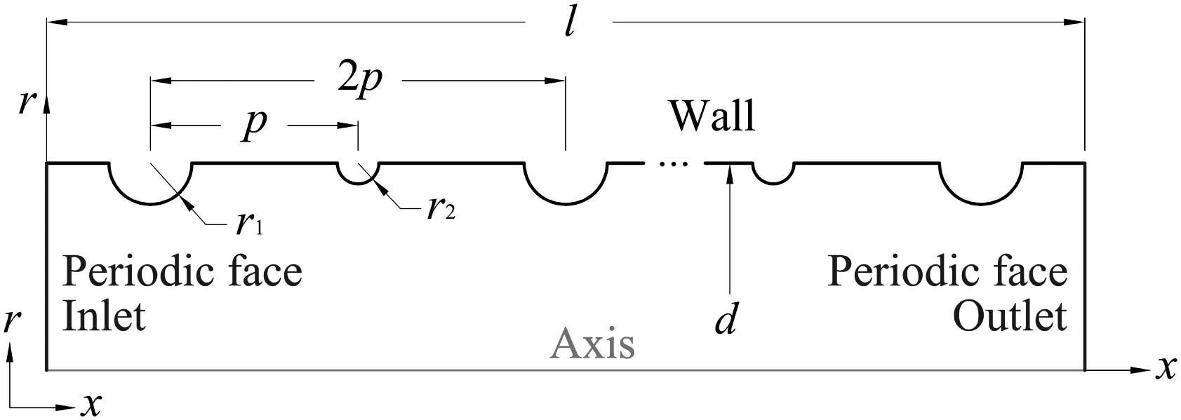
Fig.1.Geometrical structure of the corrugated tube.
The investigation is carried out under turbulent flow conditions with nine different Reynolds numbers ranging from 6000 to 57000(see in Table 1).Air is used as the working fluid in consideration of the advantage of its small specific heat and low viscosity.On the one hand,the air is helpful to get the accuracy calculation because of larger temperature differences between air inlet and outlet.On the other hand,the vortex of air will occur easily near the corrugation region.
For the numerical investigation,the assumptions followed are applied to the present study.
(1)Buoyancy effect is neglected.
(2)Air is assumed to be continuous,incompressible and Newtonian fluid.
(3)The physical properties of air are assumed to be constant and the fundamental parameters are independent of the temperature.
(4)The flow is considered to be turbulent,steady and fully developed both thermally and hydro-dynamically.
The two-equation has become a widely used turbulence model in the engineering flow calculation since it was first proposed by Launder and Spalding[26]in 1974.The standard k-epsilon model with thermal enhanced wall treatment is applied to the calculation.The boundary conditions are defined as follows:the inlet and outlet of the model are defined as periodic condition,which is shown in Fig.1.Certain mass flow rate and upstream bulk temperature(273.15 K)are applied to the air inlet and the boundary condition of the symmetric axis is applied at the down edge of the model.The constant temperature(300 K)and no-slip boundary condition are applied to the tube wall and the discretized governing equations are solved by SIMPLE(Simi-Implicit Pressure Linked Equation)algorithm option for the pressure correction process.The convective and diffusive terms are discretized by the second order upwind scheme and central difference scheme respectively.
3.Data Reduction
Data reduction of the numerical results is summarized in the following procedures.

Table 1 Geometrical parameters of the investigated tubes
The Reynolds number is calculated by Eq.(1):

where ρ is the density,μ is the dynamic viscosity,u is the average velocity of air and d is the diameter of the tube.
The average convective heat transfer coefficient is calculated by Eq.(2)[25,27]:

where,Q is the heat transfer rate defined in Eq.(3),Twis the temperature of the tube wall and Tave,ais the mass-weighted average temperature of air,which is defined as Eq.(4):

where cPis the specific heat of air,Tiis the bulk temperature of air inlet,Tois the bulk temperature of air outlet and qmis the mass flow rate,which is calculated by Eq.(5):

where A is the inside surface area of the test section,which is calculated as follows:

where L is the length of the test tube between the periodic faces.
Average Nusselt number is defined as Eq.(7):

where λ is the thermal conductivity of air.
The friction factor calculated for the smooth tube was in Eq.(8),which was proposed by Darcy[28]and Weisbach[29].

where the velocity of the fluid is defined as:

where Acis the cross-sectional area of the tube.
4.Reliability of the Numerical Simulation
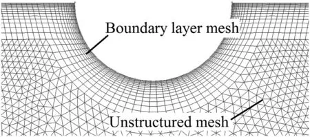
Fig.2.Grid structure of the corrugated tube.
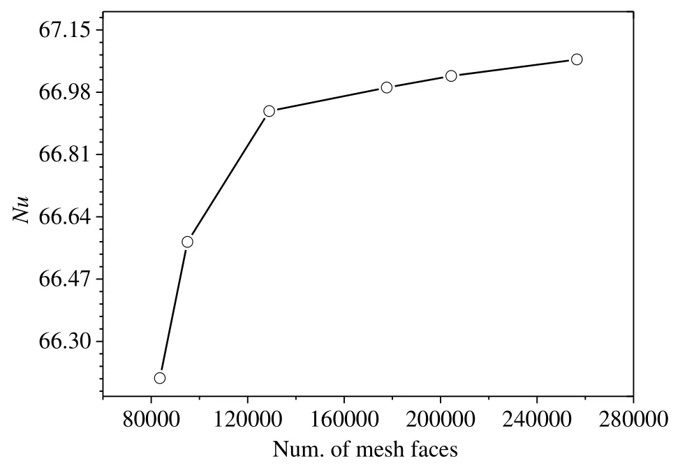
Fig.3.Grid independence test result.
In the present investigation,unstructured mesh of 15 boundary layer is applied,with the first of the unstructured mesh being 0.01 mm(see in Fig.2).In addition,the grid independence test is performed and it is found that an unstructured grid with 120000 meshes with 0.12 mm length on the wavy surface is sufficient for the present study(see in Fig.3).On the one hand,the numerical results of Nusselt vs.Reynolds number in the smooth tube are compared with the Gnielinski[30–33]and Dittus-Boelter correlations.The calculation formula of these correlations is determined by Eqs.(10)and(11)separately and the comparisons between numerical simulation and calculation results are shown in Fig.4.As can be also seen from the figure,the deviation between the present numerical data and the results of Gnielinski and Dittus-Boelter correlation is within 10%.On the other hand,the numerical friction factors of the smooth tube with different Reynolds numbers are compared with the calculation data of Filonenko equation,which is defined as Eq.(12).The comparisons of friction factor between numerical results and Eq.(12)are shown in Fig.5,which indicates that there is a good agreement(within a deviation of 5%)of friction factor between the numerical results and the Filonenko equation.Therefore it can be concluded that the numerical model used in the present study is credible enough.

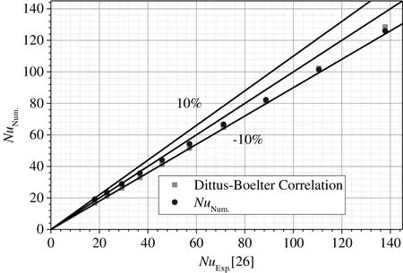
Fig.4.Comparisons of numerical results of Nusselt number with the data from Gnielinski[30–32]and Dittus-Boelter correlation for the smooth tube.
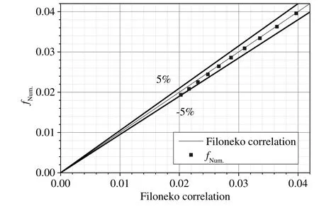
Fig.5.Comparisons of numerical results of friction factor with the data from Filonenko correlation.

5.Results and Discussion
5.1.Pressure drop
Pressure drop investigations are performed in one smooth tube and ten corrugated tubes with the Reynolds number ranging from 6000 to 57000.The calculation data of the pressure drop is reduced and the data is plotted as Fanning friction factors vs.Reynolds number in Fig.6,from which it can be concluded that the friction factors of the corrugated tubes are higher than those of the smooth tube.The augmentation value between 1.02 and 2.35 is obtained from the corrugation geometry(see in Fig.7).Fig.6 also shows that the friction factor decreases with the increase of Reynolds number ranging from 6000 to 57000,the value of which in the corrugated tubes with non-uniform corrugation(tube 03–10)are smaller than those with uniform corrugation(tube 01–02).
Similarity friction law for roughness surfaces was developed by Nikuradse[33]for sand-grained tubes and was used successfully by Webb et al.[34]for artificial roughness surface and by Vicente et al.[1]for different types of the corrugated tubes.
The roughness function R(h+)for the corrugated tubes with uniform corrugation is defined by Eq.(13).

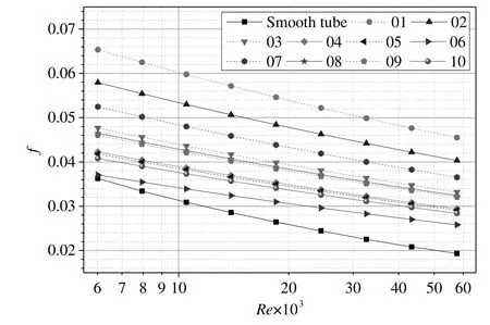
Fig.6.Friction factor vs.Reynolds number of one smooth tube and ten corrugated tubes.
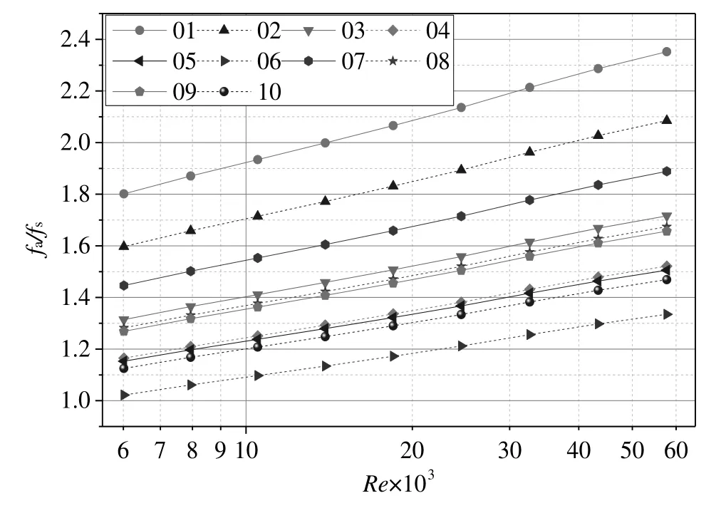
Fig.7.Friction factor augmentation(fa/fs)vs.Reynolds number of ten corrugated tubes.
where h+is roughness Reynolds number,which is defined as:

For the corrugated tubes with non-uniform corrugation,the roughness function is transformed to Eq.(15).
where roughness Reynolds numberis defined as:
The pressure drop results of ten corrugated tubes are presented in terms ofvs.in Fig.8,which indicates that the momentum roughness function does not only depend on the Reynolds number,but also on the geometry parameters of the corrugation.The momentum roughness functions in the corrugated tubes with pitch of 12.5 mm are bigger than those with 10 mm.This phenomenon has a good agreement with the results of the experiments in literature[1]and the momentum roughness functions in the corrugated tubes with nonuniform corrugation are bigger(tube 03–10)than those with uniform corrugation(tube 01–02).
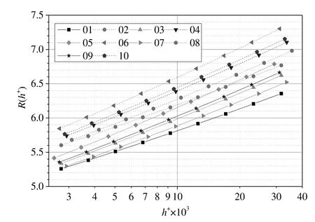
Fig.8.Momentum roughness functionvs.roughness Reynolds numberfor ten corrugated tubes.
5.2.Heat transfer
Heat transfer study under constant wall temperature condition is also carried out for all types of tubes.The Nusselt numbers changing with Reynolds numbers of different tubes are shown in Fig.9,from which it can be concluded that the Nusselt number increases with the increasing of Reynolds number,the values of which in the corrugated tubes are bigger than those in the smooth tube.The augmentation values between 1.7 and 2.2 are obtained and shown in Fig.10.
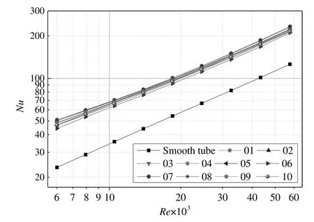
Fig.9.Nusselt number vs.Reynolds number of one smooth tube and ten corrugated tubes.
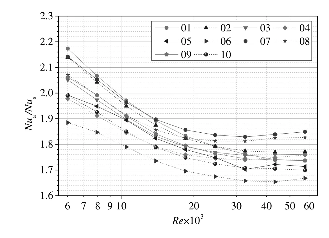
Fig.10.Nusselt number augmentation(Nu a/Nu s)vs.Reynolds number of ten corrugated tubes.
The Nusselt number presents a maximum in tube(01)when the Reynolds number increases from 6000 to 13000 and presents a maximum in tube(07–08)when the Reynolds number increases from 13000 to 57000.That is to say the geometry parameters of tube(01)have advantages on heat transfer enhancement in low Reynolds number flow region(from 6000 to 13000)and tube(07–08)have advantages on heat transfer enhancement in high Reynolds number flow region(from 13000 to 57000).Meanwhile,the heat transfer enhancement of the corrugated tubes results from the turbulence in the near-wall region,where the local surface Nusselt number increases dramatically.
In order to analyze the enhancement on heat transfer of the wall corrugation carefully,the local surface Nusselt number Nulocaldefined as Eq.(17)is adopted to clarify the heat transfer condition near the wall region and highlight the enhancement of the wall corrugation on the heat transfer.

where,Lrefis the reference length,the value of which is equal to the tube diameter.The local surface heat transfer coefficient heffis defined as:

where,Twis the wall temperature of the tube.Tave,airis the mass weighted average temperature of air(in Eq.(4)),which is chosen as the reference temperature Tref(in Eq.(19)).In the viscous sublayer of the turbulence flow,the Fourier's law is applied to calculate the heat transfer rate of fluid near the wall.The heat flux from a wall cell to the air defined as q(in Eq.(18))is computed by Eq.(20).

where η is the local coordinate normal to the wall.
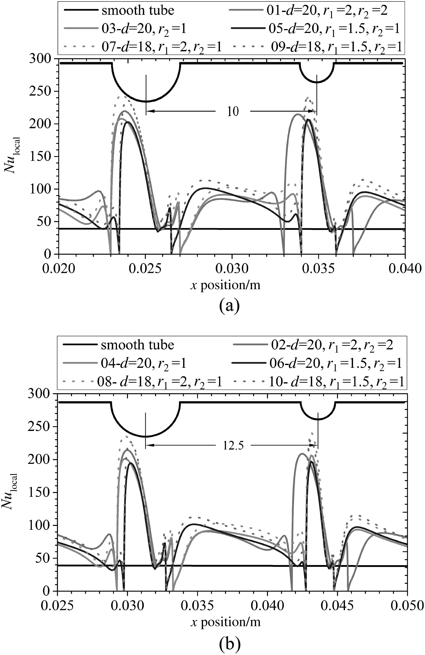
Fig.11.Local surface Nusselt number vs.x position of one smooth tube and ten corrugated tubes.(a)p=10 mm(b)p=12.5 mm at Reynolds number of 10000.
Local surface Nusselt number vs.x position of all types of tubes is presented in Fig.11,from which it can be concluded that most of the local surface Nusselt numbers in the near-wall region of the corrugated tubes are larger than that of the smooth tube and it presents the maximum value in front and top of the wavy surface.Comparing with the smooth tube,the maximum augmentation of the local surface Nusselt number in the corrugated tubes is 244 in Fig.11(a)and 238 in Fig.11(b).However,dead region exists near the root region of the corrugation,where the Nusselt number presents to zero.
For an incompressible and isotropic Newtonian fluid,air,the wall shear stress in the near wall region can be defined as Eq.(21),the graph of which in the corrugated tubes are shown in Fig.12.

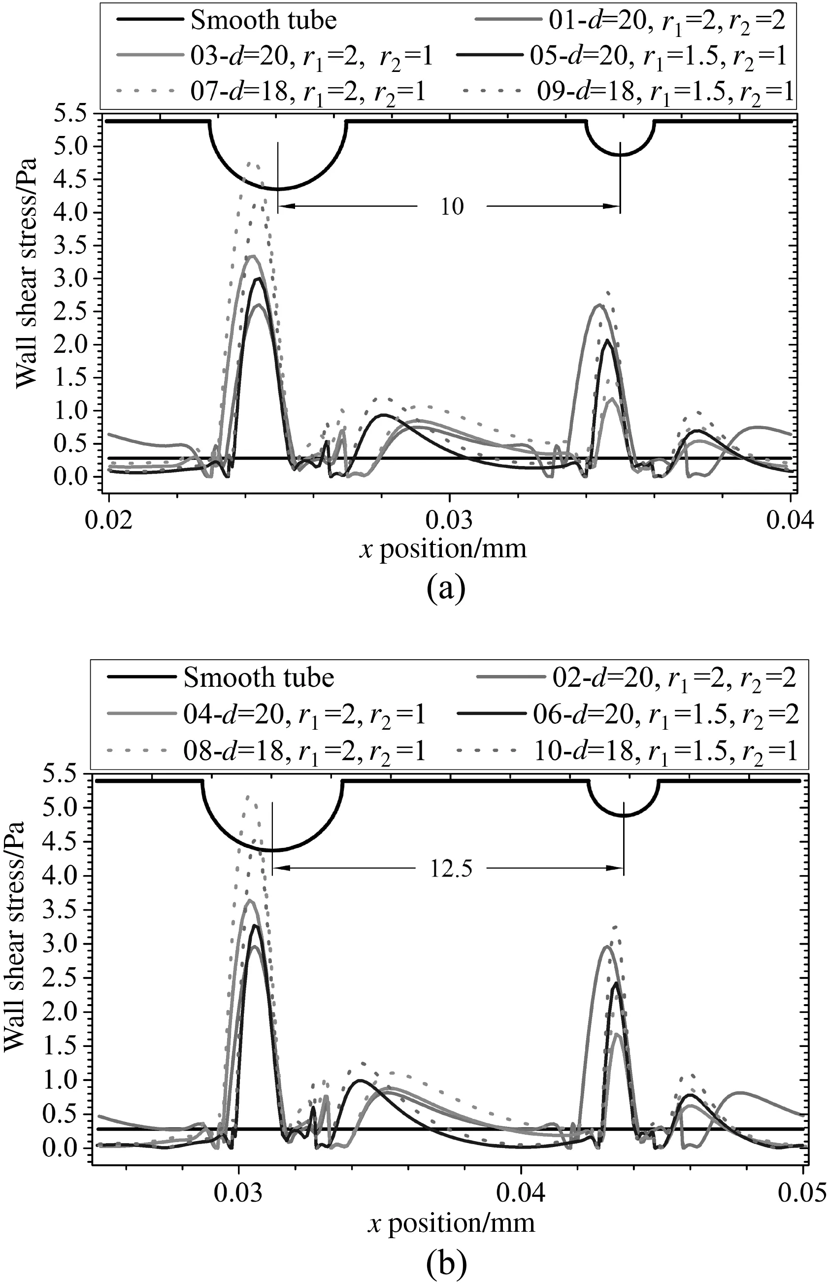
Fig.12.Wall shear stress vs.x position of one smooth tube and ten corrugated tubes.(a)p=10 mm(b)p=12.5 mm at Reynolds number of 10000.
The path lines and velocity profile contours of a type of corrugated tube(08)are shown in Fig.13,from which it can be seen that a vortex exists in the region between two adjacent corrugations.On the one hand,the existing vortex results in the mixture of air layers in the flow region,which leads to the heat transfer enhancement of air.On the other hand,the turbulence in the near-wall region is enhanced because of the vortex,which can destroy the boundary layer so that the thickness of the boundary layer becomes thinned and the wall shear stress is increased(see in Fig.12).The vortex,existed in each area between two adjacent corrugations called second flow region,is the root of the enhancement on heat transfer in the corrugated tubes.
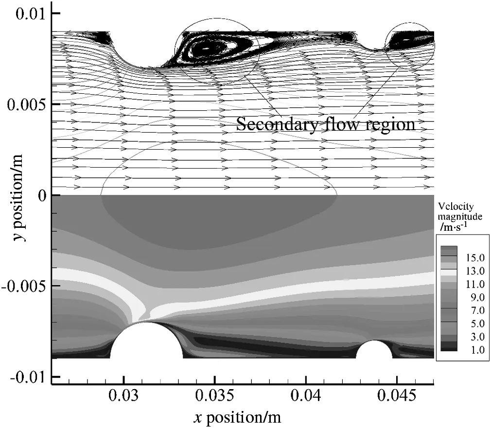
Fig.13.Path lines and velocity profile contours of tube(08)with Reynolds number of 10000.
5.3.Performance evaluation
Integrated performance evaluation is essential for the different types of the corrugated tubes.Some evaluation methods for the enhanced tubes have been presented in available literatures[1,35–37].The effectiveness factor e[35]defined as the proportion of the heat transfer to the friction factor increase ratio(in Eq.(22)),is adopted as a performance criterion for the corrugated tubes.

The effectiveness factors of ten corrugated tubes with different Reynolds number are shown in Fig.14,from which it can be concluded that the effectiveness factor decreases with the increasing of Reynolds number.Even the effectiveness factor of the corrugated tubes with uniform corrugation(01–02)is less than 1,which means that the performance of these tubes is weaken in the high Reynolds number region.As can be seen in Fig.14,the performances of the corrugated tubes with pitch of 12.5 mm have advantages than these of 10 mm under the same corrugation geometric parameter.Also,the tube(06)presents the best performance when compared with the other nine tubes.The majority of the effectiveness factor can be 1.84 when the Reynolds number is 6000.That is to say notonly the Nusselt number increase ratio,but also the friction factor increase ratio of the corrugated tubes should be taken into consideration to improve the heat transfer enhancement.Higher Nusselt number and lower friction factor will lead to a better integrated performance of the corrugated tubes,and the corrugated tube with non-uniform corrugation of bigger corrugation pitch enhances the heat transfer effectively and the friction factor won't be increased dramatically simultaneously.So this type of corrugated tube(06)has the beat integrated performance.
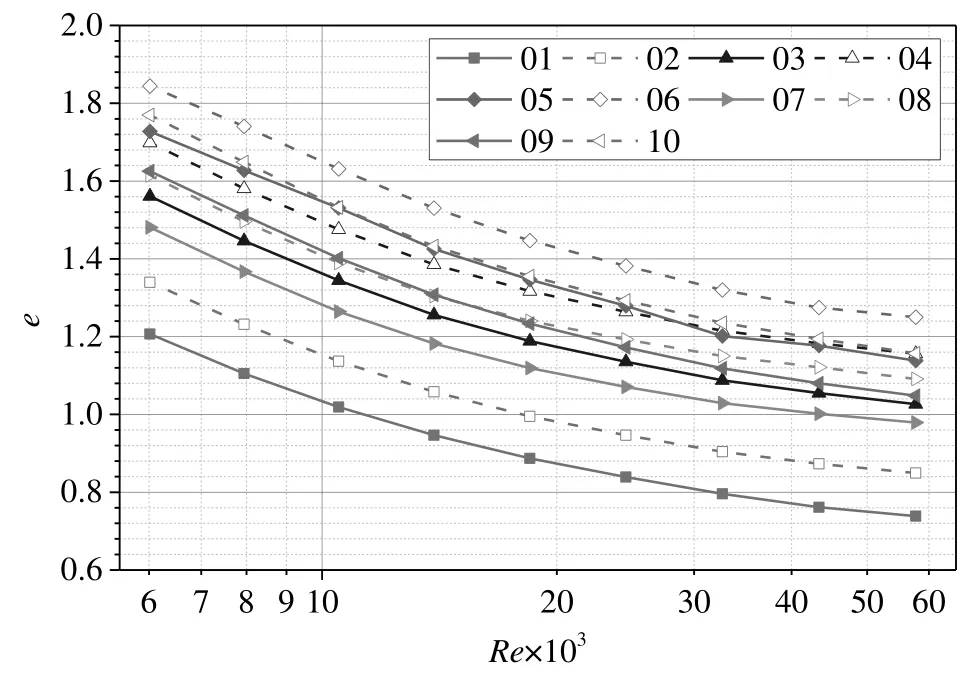
Fig.14.Performance evaluation vs.Reynolds number.
6.Conclusions
Based on finite volume method,the pressure drop and heat transfer characteristics of one smooth tube and ten different axisymmetric corrugated tubes,including two with uniform corrugation and eight with non-uniform corrugation,have been studied.Numerical simulations are carried out to explore the fully developed turbulent flow in different types of tubes.The agreement is excellent on the Nusselt number and friction factor of the smooth tube between numerical simulation results and experiments.Based on the reliability of the numerical simulation through grid independence test,the simulation investigations are carried out at the developed turbulent flow with Reynolds number ranging from6000 to 57000.Based on above conditions,several conclusions can be drawn as follows:
(1)The friction factor decreases with the increase of Reynolds number ranging from 6000 to 57000,the value of which in the corrugated tubes with non-uniform corrugation(tube 03–10)are smaller than those with uniform corrugation(tube 01–02).
(2)The Nusselt number presents a maximum in tube(01)when the Reynolds number increases from 6000 to 13000 and presents a maximum in tube(07–08)when the Reynolds number increases from 13000 to 57000.That is to say the geometry parameters of tube(01)have advantages on the heat transfer enhancement in low Reynolds number flow region(from 6000 to 13000)and tube(07–08)have advantages on heat transfer enhancement in high Reynolds number flow region(from 13000 to 57000).
(3)On the one hand,the existing vortex results in the mixture of air layers in the flow region,which leads to the heat transfer enhancement of air.On the other hand,the turbulence in the near-wall region is enhanced because of the vortex,which can destroy the boundary layer so that the thickness of the boundary layer becomes thinned and the wall shear stress is increased(see in Fig.12).The vortex,existed in each area between two adjacent corrugations called second flow region,is the root of the enhancement on heat transfer in the corrugated tubes.
(4)The effectiveness factor decreases with the increasing of Reynolds number and the performances of the corrugated tubes with pitch of 12.5 mm have advantages than these of 10 mm under the same corrugation geometric parameter.
Nomenclature
A area
cpspecific heat of air
d diameter of tube
e effectiveness factor
f Fanning friction factor
h average convective heat transfer coefficient
h+roughness of Reynolds number
L length of test section of tube
Nu Nusselt number
Pr Prandtl number
ΔP pressure drop across the test section
p pitch
Q heat transfer rate
qmmass flux of air
R(h+) momentum transfer roughness function
Re Reynolds number
T temperature
u average velocity of air in tube
η the coordinate normal to the wall
λ thermal conductivity
μ dynamic viscosity
ρ air density
Subscripts
a corrugated tube,air
a–n corrugated tube with non-uniform corrugation
c cross section
i tube inlet
local local surface region
o tube outlet
ref reference value
w tube wall
lfuid flow inside two parallel plates with wavy surface,Int.J.Eng.Sci.40(13)(2002)1495–1509.
[8]Z.Xu,Z.Zhang,Experimental investigation of the applied performance of several typical enhanced tubes,J.Enhanc.Heat Transf.17(4)(2010)331–341.
[9]A.A.R.Darzi,M.Farhadi,K.Sedighi,S.Aallahyari,M.A.Delavar,Turbulent heat transfer of Al2O3–water nano fluid inside helically corrugated tubes:Numerical study,Int.Commun.Heat Mass Transf.41(2013)68–75.
[10]S.Laohalertdecha,S.Wongwises,The effects of corrugation pitch on the condensation heat transfer coefficient and pressure drop of R-134a inside horizontal corrugated tube,Int.J.Heat Mass Transf.53(13–14)(2010)2924–2931.
[11]S.Laohalertdecha,S.Wongwises,Condensation heat transfer and flow characteristics of R-134a flowing through corrugated tubes,Int.J.Heat Mass Transf.54(11–12)(2011)2673–2682.
[12]A.Zachár,Analysis of coiled-tube heat exchangers to improve heat transfer rate with spirally corrugated wall,Int.J.Heat Mass Transf.53(19–20)(2010)3928–3939.
[13]S.Rainieri,F.Bozzoli,L.Cattani,G.Pagliarini,Compound convective heat transfer enhancement in helically coiled wall corrugated tubes,Int.J.Heat Mass Transf.59(2013)353–362.
[14]L.Liu,X.Ling,H.Peng,Analysis on flow and heat transfer characteristics of EGR helical baf fled cooler with spiral corrugated tubes,Exp.Thermal Fluid Sci.44(2013)275–284.
[15]H.Z.Han,B.X.Li,B.Y.Yu,Y.R.He,F.C.Li,Numerical study of flow and heat transfer characteristics in outward convex corrugated tubes,Int.J.Heat Mass Transf.55(2012)7782–7802.
[16]H.Z.Han,B.X.Li,F.C.Li,Y.R.He,RST model for turbulent flow and heat transfer mechanism in an outward convex corrugated tube,Comput.Fluids 91(2014)107–129.
[17]H.A.Mohammed,A.K.Abbas,J.M.Sheriff,In fluence of geometrical parameters and forced convective heat transfer in transversely corrugated circular tubes,Int.Commun.Heat Mass Transf.44(2013)116–126.
[18]S.Mac Nelly,W.Nieratschker,M.Nadler,D.Raab,A.Delgado,Experimental and numerical investigation of the pressure drop and heat transfer coefficient in corrugated tubes,Chem.Eng.Technol.38(12)(2015)2279–2290.
[1]P.G.Vicente,A.García,A.Viedma,Experimental investigation on heat transfer and frictional characteristics of spirally corrugated tubes in turbulent flow at different Prandtl numbers,Int.J.Heat Mass Transf.47(4)(2004)671–681.
[2]P.G.Vicente,A.García,A.Viedma,Experimental study of mixed convection and pressure drop in helically dimpled tubes for laminar and transition flow,Int.J.Heat Mass Transf.45(26)(2002)5091–5105.
[3]P.G.Vicente,A.García,A.Viedma,Mixed convection heat transfer and isothermal pressure drop in corrugated tubes for laminar and transition flow,Int.Commun.Heat Mass Transf.31(5)(2004)651–662.
[4]J.A.Olivier,Single-phase heat transfer and pressure drop of water cooled at a constant wall temperature inside horizontal circular smooth and enhanced tubes with different inlet configurations in the transitional flow regime,Ph D Thesis,University of Pretoria,Pretoria,2009.
[5]S.Rainieri,G.Pagliarini,Convective heat transfer to temperature dependent property fluids in the entry region of corrugated tubes,Int.J.Heat Mass Transf.45(2002)4525–4536.
[6]M.Piller,Direct numerical simulation of turbulent forced convection,Int.J.Numer.Methods Fluid 49(2005)583–602.
[7]S.Mahmuda,A.K.M.S.Islamb,M.A.Hasan Mamuna,Separation characteristics of
[19]S.Mac Nelly,W.Nadler,M.Nieratschker,K.Künster,A.Delgado,Experimentelle und numerische Untersuchung von wandnahen Str?mungen in profilierten Rohren,in:J.Czarske(Ed.),Proceedings der 23,Fachtagung Lasermethoden in der Str?mungsmesstechnik,GALA,Karlsruhe,2015.
[20]A.Harle?,E.Franz,M.Breuer,Heattransfer and friction characteristics of fully developed gas flow in cross-corrugated tubes,Int.J.Heat Mass Transf.107(2017)1076–1084.
[21]A.Harle?,E.Franz,M.Breuer,Experimental investigation of heat transfer and friction characteristic of fully developed gas flow in single-start and three-start corrugated tubes,Int.J.Heat Mass Transf.103(2016)538–547.
[22]A.García,J.P.Solano,P.G.Vicente,A.Viedma,The in fluence of artificial roughness shape on heat transfer enhancement:Corrugated tubes,dimpled tubes and wire coils,Appl.Therm.Eng.35(2012)196–201.
[23]W.L.Chen,Z.Guo,C.K.Chen,A numerical study on the flow over a novel tube for heat-transfer enhancement with a linear Eddy-viscosity model,Int.J.Heat Mass Transf.47(14–16)(2004)3431–3439.
[24]B.Li,B.Feng,Y.L.He,W.Q.Tao,Experimental study on friction factor and numerical simulation on flow and heat transfer in an alternating elliptical axis tube,Appl.Therm.Eng.26(17–18)(2006)2336–2344.
[25] ?.A?ra,H.Demir,?.?.Atay?lmaz,F.Kanta?,A.S.Dalk?l??,Numerical investigation of heat transfer and pressure drop in enhanced tubes,Int.Commun.Heat Mass Transf.38(10)(2011)1384–1391.
[26]B.E.Launder,D.B.Spalding,The numerical computation of turbulent flows,Comput.Methods Appl.Mech.Eng.3(1974)269–289.
[27]M.Rahimi,S.R.Shabanian,A.A.Alsaira fi,Experimental and CFD studies on heat transfer and friction factor characteristics of a tube equipped with modified twisted tape inserts,Chem.Eng.Process.Process Intensif.48(3)(2009)762–770.
[28]H.Darcy,Recherches experimentales relatives au mouvement de l'Eau dans les Tuyaux,Mallet-Bachelier,Paris,1857.
[29]J.Weisbach,Lehrbuch der Ingenieur und Maschinen-Mechanik,Braunschwieg,1845.
[30]V.Gnielinski,New equations for heat mass transfer in turbulent pipe and channel flow,Int.J.Chem.React.Eng.16(1976)359–368.
[31]V.Gnielinski,Turbulent heat transfer in annular spaces—A new comprehensive correlation,Heat Transf.Eng.36(9)(2014)787–789.
[32]V.Gnielinski,Corrigendum to “on heat transfer in tubes”[International Journal of Heat and Mass Transfer 63(2013)134–140],Int.J.Heat Mass Transf.81(2015)638.
[33]J.Nikuradse,Laws of F l o w in R ough P ipes,Technical Report Archive&Image Library,(1950).
[34]R.L.Webb,R.G.Eckert,R.J.Goldstein,Heat transfer and friction in tubes with repeated-rib roughness,Int.J.Heat Mass Transf.14(1971)601–617.
[35]Y.Wang,Y.L.He,Y.G.Lei,J.Zhang,Heat transfer and hydrodynamics analysis of a novel dimpled tube,Exp.Thermal Fluid Sci.34(8)(2010)1273–1281.
[36]V.D.Zimparov,V.M.Petkov,A.E.Bergles,Performance characteristics of deep corrugated tubes with twisted-tape inserts,J.Enhanc.Heat Transf.19(1)(2012)1–11.
[37]V.Zimparov,Extended performance evaluation criteria for enhanced heat transfer surfaces:Heat transfer through ducts with constant wall temperature,Int.J.Heat Mass Transf.43(2000)3137–3155.
 Chinese Journal of Chemical Engineering2018年3期
- Chinese Journal of Chemical Engineering的其它文章
- Investigations on pool boiling critical heat flux,transient characteristics and bonding strength of heater wire with aqua based reduced graphene oxide nano fluids
- Heavy metals adsorption by banana peels micro-powder:Equilibrium modeling by non-linear models
- Potential aspect of rice husk biomass in Australia for nanocrystalline cellulose production
- Fouling evaluation on membrane distillation used for reducing solvent in polyphenol rich propolis extract
- Investigation on a vertical radial flow adsorber designed by a novel parallel connection method☆
- Synthesis,adsorption and selectivity of inverse emulsion Cd(II)imprinted polymers☆
