Disturbance Observer Based Control for Four Wheel Steering Vehicles With Model Reference
Shuyou Yu,Member,IEEE,Jing Wang,Yan Wang,Hong Chen,Senior Member,IEEE
Abstract—This paper presents a disturbance observer based control strategy for four wheel steering systems in order to improve vehicle handling stability.By combination of feedforward control and feedback control,the front and rear wheel steering angles are controlled simultaneously to follow both the desired sideslip angle and the yaw rate of the reference vehicle model.A nonlinear three degree-of-freedom four wheel steering vehicle model containing lateral,yaw and roll motions is built up,which also takes the dynamic effects of crosswind into consideration.The disturbance observer based control method is provided to cope with ignored nonlinear dynamics and to handle exogenous disturbances.Finally,a simulation experiment is carried out,which shows that the proposed four wheel steering vehicle can guarantee handling stability and present strong robustness against external disturbances.
I.INTRODUCTION
W ITH the rapid development of automobile industry,handling stability related to vehicle safety has attracted more attention.The four wheel steering(4WS)vehicles have been studied in order to improve the maneuverability of vehicle at low speed and enhance the stability at high speed.As rear wheels participate in steering process,the transient response of a vehicle can be improved[1],[2].
Traditional 4WS vehicles mainly refer to automobiles with active rear wheel steering systems,and their control types include both feedforward control and feedback control[3].Early 4WS vehicles intend to achieve zero sideslip angle to reduce the phase difference between lateral acceleration and yaw rate.This kind of 4WS vehicles usually use a feedforward control method.Sano proposes a ratio between rear wheels and front wheels,which can guarantee a zero sideslip angle during steady steering[4].This method is easy to implement,but it increases the time it takes for yaw rate and lateral acceleration to reach steady states.Thus,it does not perform well during transient motion.For 4WS vehicles using the feedback control method,two control strategies are presented.One also focuses on reaching a zero sideslip angle,the other focuses on tracking the reference yaw rate.The feedback control method has the characteristic of fast response,which can effectively reduce the effect of external disturbances.Quite a few modern 4WS control methods are established based on it.In[5],a set of linear maneuvering equations representing 4WS vehicle dynamics is used,which formulates the multi-objective vehicle controllers as a mixed H2/H∞synthesis.A fuzzy controller based on the state feedback and the sliding-mode control methods is proposed for high-speed 4WS vehicles in[6].Considering the uncertain problems for 4WS control,robust control schemes have been adopted in[7]-[10].
The development of the steer-by-wire(SBW)technique has made it possible for front and rear wheels to actively steer,simultaneously[11].In this paper,motivated by this idea,the strategy of model reference control is proposed in order to achieve both the desired sideslip angle and the yaw rate.With the combination of feedforward control and feedback control,front wheel active steering and rear wheel active steering are used to achieve the desired performance of a reference vehicle model.In[12],a similar model reference control strategy has also been used,where a H∞output feedback controller is designed.Its simulation results show that the proposed 4WS vehicle can improve vehicle handling and stability,but it only focuses on a linear 4WS model.In this paper,a nonlinear three degree-of-freedom(3DOF)4WS vehicle model which contains the dynamic effects of crosswind is built up.The model will be used to verify the effectiveness of the proposed controllers.In order to implement it easily,a relatively simple vehicle model,a linear two degree-of-freedom(2DOF)4WS vehicle model,is used in the controller design stage.While the feedforward and feedback controllers we designed do not consider ignored nonlinear dynamics and external disturbances existing in 4WS system,a disturbance observer based control(DOBC)method is provided to attenuate disturbances.
The rest of this paper is organized as follows.4WS vehicle models are built up in Section II.Section III describes the main results for 4WS control strategy.Disturbance observer based control scheme is illustrated in Section IV.The simulation results are carried out in Section V.Section VI concludes the paper with a short summary.
II.4WS VEHICLEMODELS
In this section,4WS vehicle models will be of interest.Firsta 3DOF 4WS vehicle model with a nonlinear tyre model is set up,which also takes the crosswind disturbance into consideration.Such a model captures the most relevant characteristics associated to lateral and longitudinal stabilization of 4WS vehicle.For simplicity and easy implementation,a linear 4WS vehicle model is used for the design of controllers.
A.Nonlinear 4WS Vehicle Model
A nonlinear 3DOF 4WS vehicle model is shown in Fig.1.The body frame(x,y,z)is fixed at the vehicle’s center of gravity(CG).In Fig.1,β and r are the sideslip angle and the yaw rate of vehicle at CG.m is vehicle mass,msis sprung mass.hsis the height of sprung mass CG above roll axis,hgis the height of sprung mass CG above ground.? and˙? are roll angle and roll velocity,Ixis the roll moment of inertia of the sprung mass about x axis,Izis the yaw inertia moment about z axes,and Ixzis the product of inertia of the sprung mass about x and z axes.C?is roll damping of vehicle suspension,and k?is roll stiffness of vehicle suspension.v is the vehicle longitudinal velocity,a and b are longitudinal distances from the front and rear axle to the CG,and L=a+b is the wheelbase of vehicle.Ffand Frdenote the lateral forces of front and rear wheel respectively.
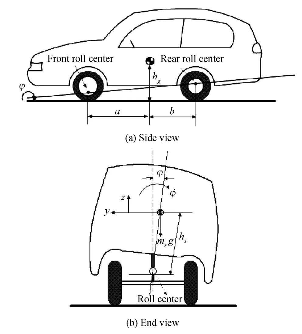
Fig.1.The diagram of 3DOF vehicle model.
Considering lateral,yaw and roll motions,the 3DOF vehicle model of the 4WS system is given by[5],[13]

where Fy,Mzand Lxare the sums of the external forces and moments acting on the vehicle measured at CG along the car axes.
As crosswind has some influences on dynamics of the 4WS system,the following equations are

where Fwis the crosswind force,hwis the height of crosswind force acting point above roll axis,and lwis the horizontal distance from crosswind force acting point to vehicle’s CG.
The magic formula tyre model[14]is adopted here to determine the lateral force of front and rear wheels

where Fiand αirepresent the lateral force of a wheel and its corresponding slip angle.The parameters B,C,D and E are determined by the tyre structure and the tyre vertical load.
Assume that β is small and v varies slowly,the front slip angle αfand the rear slip angle αrcan be derived by

where δfand δrare respectively the steering angles of the front and rear wheels.
The vertical load of each tyre includes both the static load and the lateral load transfer caused by the vehicle rolling motion
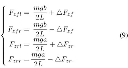
The lateral load transfer is given by[5]

where musfand musrare the front and rear axle loads of unsprung mass,hufand hurare the heights of unsprung mass CG above the front and rear axles,lfsand lrsare the longitudinal distances from the front and the rear axles to the sprung mass CG.Efand Erare the front and rear wheel tracks,C?fand C?rare the roll damping of the front and rear suspensions,k?fand k?rare the roll stiffness of the front and rear suspensions,respectively.
B.Linear 4WS Vehicle Model
In order to implement easily,it is reasonable to use a relatively simple vehicle model in the stage of controller design.Two degree-of-freedom vehicle model contains sideslip and yaw rate,which captures the most relevant dynamics of a 4WS vehicle.As is shown in Fig.2,the coordinate frame is fixedat the vehicle’s CG.According to Newton’s second law,the vehicle dynamic equations can be written as

While the tyre slip angle is small,the front and rear lateral tyre forces vary linearly with their slip angles

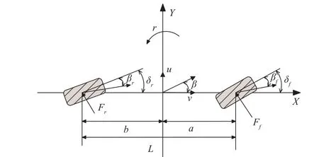
Fig.2.The diagram of 2DOF vehicle model.
where kfand krare the cornering stiffness of the front and rear wheels.The front slip angle αfand rear slip angle αrare obtained from(8).Then,(11)can be rewritten as

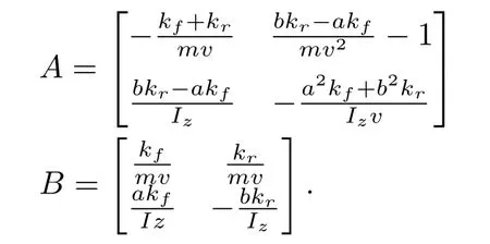
From(13),the state space representation of the linear 4WS vehicle model can be expressed as

where x=[β r]Tis the state vector,u=[δfδr]Tthe input vector.The coefficient matrices are given as follows
Taking the external disturbances caused by the crosswind into consideration,(11)can be rewritten as

In accordance with(14),the state space representation of(15)can be written as

where w?f=F?w/mv is the normalized disturbance input,and Bf=.The key parameters of 4WS vehicle model used in this paper are collected in Table I[13].
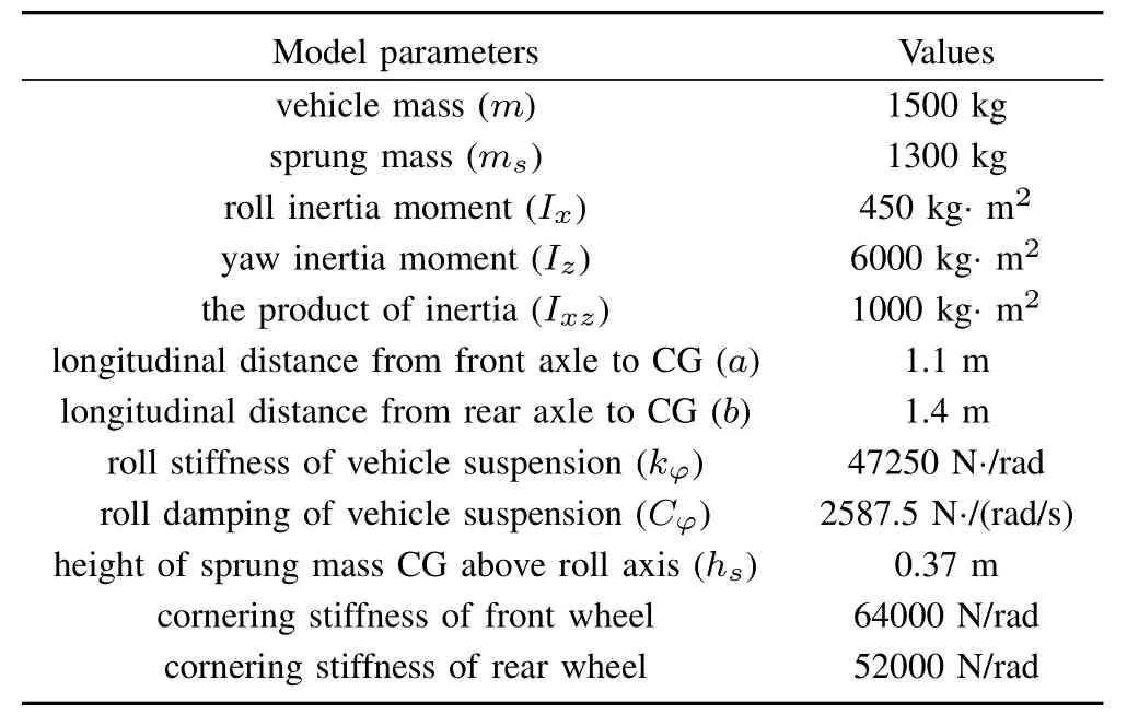
TABLE I PARAMETERS OF4WS VEHICLEMODEL
III.CONTROLOF 4WS
The performance requirement of a 4WS vehicle is to improve the vehicle maneuverability at low speed and to enhance vehicle handling stability at high speed.The strategy of 4WS control is proposed in Fig.3,where the 4WS control problem is simplified as a yaw rate and a sideslip angle tracking problem.is the front wheel angle input given by the driver.In order to improve steering characteristics,both the front wheel angel δfand the rear wheel angle δrare chosen as controlled quantities.The desired yaw rate and sideslip angle are provided by the reference model,while the feedback controller is designed to minimize tracking errors.The feedforward controller proposed here guarantees that tracking errors are not too large,which is derived based on the reference model as well.Hence the total control input u is composed of the feedforward control input ufand the feedback control input ue,that is

Note that crosswind disturbances here are not considered.In the next section,a disturbance observer will be introduced so as to attenuate the effects of crosswind disturbances.

Fig.3. Model reference control of 4WS vehicle.
A.Reference Model
In order not to change the driver’s perception of vehicle handling,the steady state value of desired reference yaw rate should be the same as that of the front wheel steering(FWS)vehicle with the same parameters.Based on vehicle theory,the desired yaw rate can be described as follows[15]:

where r?represents the desired reference yaw rate,the front wheel angle,k the vehicle stability factor,and τrthe time constant of yaw rate.The desired reference sideslip is also approximated as a first order inertia transfer function of the front wheel angle[15],

where β?represents the desired reference sideslip angle,and τβis the time constant of the sideslip angle.The term kβis a proportional gain,which is usually a small constant and can be set to zero in the ideal situation.Thus,kβ=0 is chosen in this paper.
Define the state vector xd=[β?r?]Tand the control input vector ud=.The state space equation of the reference vehicle model can be expressed as

where

B.Feedforward Controller
Applying Laplace transform on the linear 4WS vehicle model(14),the transfer function matrix can be obtained

The role of feedforward controller Cf(s)is to keep the dynamic response of the linear 4WS vehicle model and the reference model the same.If a given front wheel angle goes through the feedforward controller and the 4WS vehicle model,cf.Fig.3,the desired reference sideslip angle and yaw rate could be obtained as

Substituting(18),(19)and(21)into(22),the feedforward controller can be obtained

Then the feedforward control input can be expressed as

C.Feedback Controller
A state feedback controller will be proposed in this part.Define the following error vector as

According to(16),(17)and(20),we get

Substituting(24)into(22),we have

Substituting(21)into(27)and then applying Laplace inverse transform,we get

Substituting(28)and(20)into(26),the last two terms of(26)are eliminated.Thus a simple state space description of the error system is achieved

Here we design a linear quadratic regular(LQR)controller without considering disturbances that will be dealt with in the next section.The performance index J is shown as follow

where Q≥0 and R≥0 are the weighting matrices

The obtained LQR feedback control gain is

IV.DISTURBANCEOBSERVERBASEDCONTROL
In this section,a disturbance observer is designed to deal with the crosswind.Furthermore,this disturbance observer also takes the ignored nonlinear dynamics into account.As the linear vehicle model inevitably neglects some high order nonlinear terms compared with nonlinear vehicle model,a nonlinear function O(xe,ue,wf)is added to(29)

The DOBC approach[16]is used to deal with both disturbances and uncertainties.For simplicity,the effect caused by nonlinearities is merged into the disturbance term,i.e.,

Substituting(32)into(31),the full dynamic model of the nonlinear 4WS vehicle is described as

where Bd=I is a 2×2 identity matrix.For system(33),the following disturbance observer is employed to estimate the disturbances


The disturbance observer control law of system(33)is designed as[16]

where Keis the LQR feedback control law.Here we select the observer gain matrix as

The control structure of the nonlinear 4WS vehicle with the proposed control strategy is shown in Fig.4.The disturbance compensation gain vector can be obtained based on(35),where

V.SIMULATION
In this section,some simulation results are given to show the effectiveness of the proposed control strategies for 4WS systems.Choose the vehicle forward velocity as v=20m/s(72km/h)and the step front wheel input as=0.087(5?),cf.Fig.5.The crosswind disturbance is presented in Fig.6.In the same condition,the experimental results for the 4WS vehicle with or without the disturbance observer(the corresponding control strategies are shown in Fig.3 and Fig.4)are discussed,while a conventional front wheel steering(FWS)vehicle and a 4WS vehicle with proportional controller are also implemented for comparison.The classic proportional control method uses a speed dependent ration between rear and front wheels in an open-loop controller in order to achieve a zero sideslip angle during directional maneuvers.The ratio between the front and the rear wheel is described as[1]:

As shown in Fig.7,the steady-state gain of sideslip angle of 4WS vehicles with or without disturbance observer is much smaller than the one of the proportional control,but the control strategy with disturbance observer is slightly better.In cases where crosswind disturbances occur,both proposed strategies show great advantages.However,only the yaw rate of the 4WS vehicle with disturbance observer can achieve zero tracking error in the steady-state without overshoot Compared with the proportional control for 4WS vehicle,the proposed 4WS control strategies can provide drivers a familiar driving sensation.In addition,the proposed controller both work very well against the crosswind disturbance that occurred from 2s to 4s,while the 4WS vehicle based on DOBC is clearly superior.
On the basis of analyses,it is shown that the proposed disturbance observer based control strategy not only copes with the ignored nonlinear dynamics,but also presents strong robustness against external disturbances.Since there are ignored nonlinear dynamics,it can not achieve desired tracking performance.Although the feedback structure effectively reduces the effect of crosswind disturbances,the additional DOBC can have a better control effect.
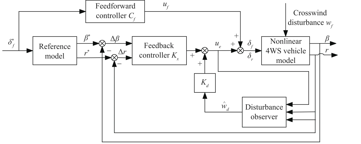
Fig.4. 4WS vehicle with the proposed control strategy.
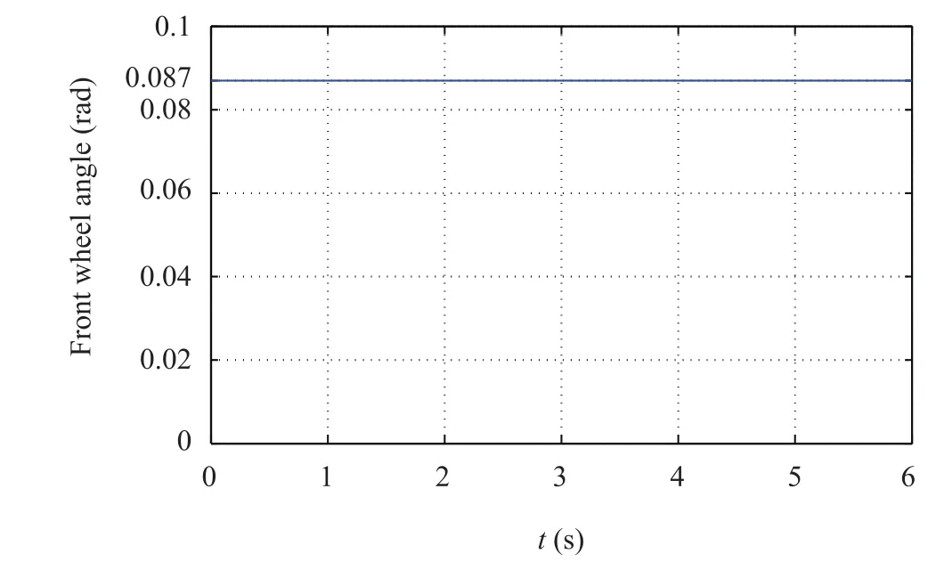
Fig.5. Front wheel angle input.
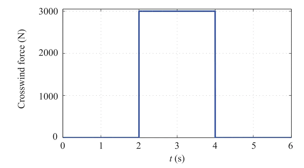
Fig.6. Crosswind disturbance input.

Fig.7.The responses of step steering angle input:4WS vehicle with disturbance control(cf.Fig.4),4WS vehicle without disturbance control(cf.Fig.3),classic proportional control 4WS vehicle,FWS vehicle.
VI.CONCLUSIONS
In this paper,a 4WS control strategy based on DOBC approach was presented.First,a nonlinear 3DOF 4WS vehicle model involving dynamic effects of crosswind was introduced.In the stage of controller design,a relatively simple vehicle model,the linear 2DOF 4WS vehicle model,was used.Taking the ignored nonlinear dynamics and crosswind disturbances into consideration,a disturbance observer was designed.Finally,step response experiments were carried out,which showed that the proposed 4WS vehicle with disturbance observer is superior to the 4WS vehicle without the disturbance observer,FWS vehicle,and 4WS vehicle with the classical proportional control.The proposed scheme not only copes with ignored nonlinear dynamics,but also presents strong robustness against external disturbances.
 IEEE/CAA Journal of Automatica Sinica2018年6期
- IEEE/CAA Journal of Automatica Sinica的其它文章
- Granular Computing for Data Analytics:A Manifesto of Human-Centric Computing
- The Cubic Trigonometric Automatic Interpolation Spline
- Mathematical Study of A Memory Induced Biochemical System
- Predictive Tracking Control of Network-Based Agents With Communication Delays
- Necessary and Sufficient Conditions for Consensus in Third Order Multi-Agent Systems
- Self-Tuning Asynchronous Filter for Linear Gaussian System and Applications
