Post-Processing Time-Aware Optimal Scheduling of Single Robotic Cluster Tools
QingHua Zhu,, Yan Qiao,, NaiQi Wu,, and Yan Hou
Abstract—Integrated circuit chips are produced on silicon wafers.Robotic cluster tools are widely used since they provide a reconfigurable and efficient environment for most wafer fabrication processes. Recent advances in new semiconductor materials bring about new functionality for integrated circuits. After a wafer is processed in a processing chamber, the wafer should be removed from there as fast as possible to guarantee its high-quality integrated circuits. Meanwhile, maximization of the throughput of robotic cluster tools is desired. This work aims to perform post-processing time-aware scheduling for such tools subject to wafer residency time constraints. To do so, closed-form expression algorithms are derived to compute robot waiting time accurately upon the analysis of particular events of robot waiting for singlearm cluster tools. Examples are given to show the application and effectiveness of the proposed algorithms.
I. Introduction
TO produce integrated circuit chips, a silicon wafer goes through a great number of fabrication procedures, up to hundreds of steps. Many of these wafer fabrication steps are performed using cluster tools [1], [2]. Typically, four to six processing machines/modules (PM) radially surround a robot to form a cluster tool in a vacuum environment, as illustrated in Fig. 1. The loadlock cassette modules (LL) are used to import/export raw/processed wafers. The robot in the center is responsible for transferring wafers between PMs/LLs. Depending on the number of blades (one or two), a single or dual-arm robot can handle one or two wafers at a time, respectively. The robot unloads a raw wafer from LLs, transfers it to PMs for processing pursuant to a predefined recipe, and returns the completed wafer to LLs [2], [3].
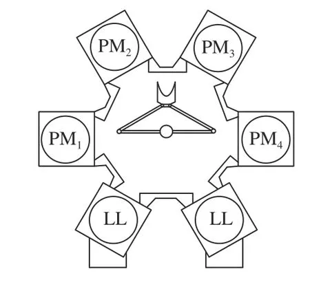
Fig. 1. A single-arm cluster tool.
Cluster tools can perform most wafer fabrication processes,including etching, vapor deposition, wafer cleaning and so on,making them increasingly prevalent in the fabrication processes. Just as done for scheduling complex production systems [4]–[7], much effort has been made on modeling,analysis and scheduling of cluster tools [8]–[24]. Chemical vapor deposition (CVD) used in various wafer fabrication processes require the avoidance of excessive exposure to mixed chemical gases at high temperatures. A wafer thus must be unloaded within a short time from a processing chamber after its processing is completed.
Abundant work has been done for scheduling cluster tools that are subject to such wafer residency time constraints [3],[25]–[29]. In particular, Kimet al. [30], Lee and Park [31],and Zuberek [29] have investigated the optimal scheduling problems of dual-arm cluster tools subject to wafer residency time constraints. For cluster tools under such constraints,further work is done in [32]–[35] and analytical-expressionbased algorithms are proposed to find periodic optimal schedules whenever a feasible schedule exists. Petri nets have been effectively applied to model cluster tools [32]–[36] and other discrete event systems [37], [38].
A cluster tool starts its operation via a start-up transient process when its robot unloads the first wafer from LLs [39].Then, it enters the steady state [40], and eventually it undergoes a close-down transient process to terminate its operation when no raw wafers are released from LLs. Yiet al.[40] handle the operations under the steady state. Under the steady state, cycle time is referred to as the time taken for finishing a wafer in a repetitive manner [1]. In recent years,due to preferences for small lot production [14], [41], [42] and maintenance demands [43], [44], transient periods including start-up and close-down processes increase to a large proportion during the whole wafer fabrication. The work in[45] studies a generalized backward sequence and workloadbased conditions to minimize makespan for scheduling such transient processes of single-arm cluster tools with parallel PMs. Kimet al. [46] developed latest and earliest starting policies to minimize start-up and close-down periods for dualarm cluster tools under wafer residency time constraints. For start-up and close-down periods of single-arm cluster tools with wafer residency time constraints, the work in [47]–[49]analyzes schedulability conditions and finds optimal schedules. Kimet al. [50] investigate the scheduling problem of start-up and close-down periods for cluster tools subject to task time variation and wafer residency time constraints.
Thanks to significant advancements of semiconductor nanomaterial [51], such as carbon nanotubes and graphene,up-to-date wafer circuit line width has been reduced to less than ten nanometers. As an example, CVD involves a chemical reaction between a mixture of gasses and a wafer’s surface that takes place at temperatures up to 1000oC. For thin line width circuits, there are complex and delicately controllable growth kinetic and reactions to form the circuit layer (s) through CVD. The duration of certain sub-steps has a great influence on the high-quality synthesis of monolayer,bilayer, or few-layer graphene [52]. The quality of devices fabricated on a wafer is heavily dependent on reaction time[51], [53]. Thus, there is an upper-limit with regards to time for which a wafer may stay in a chamber after its processing.If the wafer remains in the chamber past this time limit, it would typically be scrapped. It is crucial to minimize postprocessing time for large wafers so that their surfaces absorb fewer by-products in the chamber and can be fabricated uniformly [52]. Therefore, it is desirable to maximize the productivity of wafer fabrication, while minimizing the postprocessing time to satisfy the requirement for yielding highquality circuits.
To the authors’ best knowledge, this issue has not been tackled in the literature yet. The main difference between this work and the prior work on scheduling cluster tools is that the latter [3], [10], [13], [54], including our previous work [32],[49], does not consider post-processing time minimization.Since post-processing time minimization and throughput maximization may be in conflict, it can be extremely challenging to find an optimal schedule to optimize both.Furthermore, determining a one-wafer schedule which is simple and easy to understand and implement by practitioners is not obvious. The semiconductor industry prefers one-wafer cyclic scheduling during which after a sequence of robot actions is performed, a cluster tool maintains the exact same state throughout the entire process [10]. Owing to the high capital cost of cluster tools, maximizing throughout is of significant importance in wafer fabrication, we aim to achieve minimization of post-processing time. Despite the scheduling algorithms in prior work which guarantees that postprocessing time does not exceed its upper-limit, it is not advised that the post-processing time of a wafer is longer at some steps while it is shorter at other steps because of quality considerations.
This work has twofold contributions: 1) an optimal onewafer cyclic schedule that maximizes a cluster tool’s throughput is found and then the post-processing time is minimized for single-arm cluster tools; and 2) the postprocessing time difference among the processing steps is minimized as much as possible. This work proposes algorithms to get an exactly optimal solution in linear-time method instead of a population-based optimization one[55]–[58].
The remainder of this paper is structured as follows. Section II presents the fundamental temporal properties of scheduling single-arm cluster tools. Section III presents algorithms to find a schedule that can minimize cycle time and total postprocessing time for single-arm cluster tools. Section IV demonstrates the application of the proposed algorithms.Section V summarizes this work.
II. Temporal Properties of Single-arm Cluster Tools
Withnprocessing steps in a cluster tool, letandFor easy presentation, suppose that each processing step is configured with one PM. For the example shown in Fig. 1, without loss of generality, it is assumed that the wafer processing route is 〈 LL→ PM1→PM2→ PM3→ PM4→ LL〉. For single-arm cluster tools, letλandμdenote the time taken for robot loading/unloading a wafer into/from LLs, and robot moving between any two PMs or between a PM and an LL, respectively. Letωidenote robot waiting time before unloading a wafer from PMi. If the workload bottleneck is the robot, the cluster tool runs in a transport-bound mode; while if the bottleneck is a PM, it runs in a process-bound mode. Backward scheduling is optimal for the steady state of single-arm cluster tools operating in a process-bound mode [10]. By this scheduling rule, the robot performs the operation sequence as follows:
〈 moving to PMn→ waiting there forωntime units →unloading a wafer from PMn→ moving to LLs → loading the wafer into LLs → moving to PMn–1→ waiting there forωn–1time units → unloading a wafer from PMn–1→ moving to PMn→ loading the wafer into PMn→ moving to PMn–2→waiting there forωn–2time units → unloading a wafer from PMn–2→…→ unloading a wafer from PM1→…→ moving to LLs → waiting there forω0time units → unloading a wafer from LLs → moving to PM1→ loading the wafer into PM1→moving to PMnagain〉.
Letαidenote the wafer processing time at Stepior PMi.After a wafer is completed at Stepi, it cannot stay there for more thanδi(≥ 0) time units, which is also the upper limit of post-processing time at Stepi. Some temporal properties of single-arm cluster tools are recalled as follows [32].
The robot cycle time is

where the robot’s task timeψ1= 2(n+ 1)(λ+μ) is a constant,whileis its waiting time in a cycle.
At Stepi, the lower bound time required to finish a wafer is

and the upper bound time required to finish a wafer is

Letτidenote the wafer sojourn time at Stepi. A wafer should stay in PMiforτi≥αitime to complete its processing,which can be calculated as

III. Post-processing Time-aware Scheduling
Letri=τi–αidenote the post-processing time at Stepi. By(4), it is known that ifωi–1increases, thenridecreases. The key issue is to minimize the total postprocessing time
For a single-arm cluster tool in a process-bound mode, its lower bound of cycle time isWhen a cluster tool operates in a one-wafer cyclic schedule, the robot and all the processing steps operate in a paced way, i.e.,ψ=Π. Our goal is to schedule the robot to achieve its cycle time as Π so as to minimize the cycle time for a tool. To avoid violating wafer residency time constraints, schedulability conditions must be established. Upon these conditions,schedules are found to optimize these two objectives. In (1),we havewhich implies that if a feasible schedule exists, we must properly assignintosuch that the obtained schedule is feasible. When the cycle time is minimal and wafer residency time constraints are satisfied,must be minimized in order to guarantee high-quality circuits on a wafer. Furthermore, whenis minimized,one must have a uniform substrate across the wafer, or the post-processing time should be evenly distributed among the processing steps. Note that there may be a variety of feasible schedules by assigningintoThe optimal one achieves the uniformity amongri’s orri=rj,i,. To obtain such a result, we minimize the sum of post-processing timeri’s, which is one of the objectives. In this work, sinceλ,μ, andαi’sare constants, ifωi’s are determined, a schedule is found as well.
Based on the above discussion, we propose Algorithm 1 to assignψ2intoso as to obtain a schedule. To calculate a schedule, we must ensure that a feasible schedule exists, since otherwise, it is meaningless. There are two cases where a feasible schedule exists.Case 1:One of the following conditions should be met:1) Π ≤ ΠiUandand 2)Note that |V| denotes the cardinality of setV. Condition 1)means that the workloads of all processing step are relatively balanced and the cluster tool is process-bound, while Condition 2 says that the robot is always busy, i.e., the cluster tool is transport-bound.
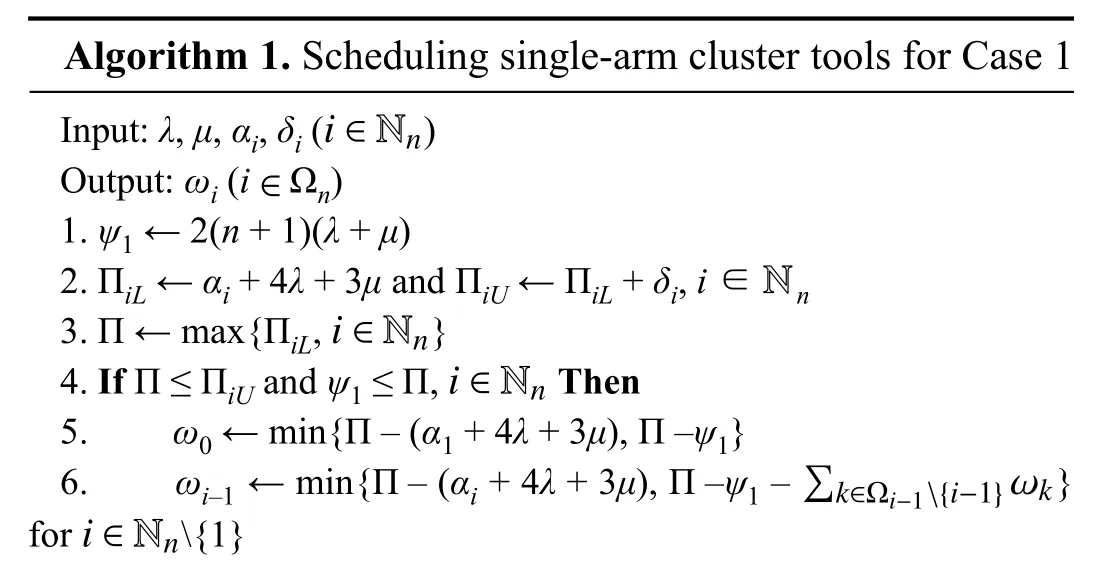
Algorithm 1. Scheduling single-arm cluster tools for Case 1 i ∈Nn Input: λ, μ, αi, δi ( )Output: ωi (i Ωn)1. ψ1 ← 2(n + 1)(λ + μ)∈2. ΠiL ← αi + 4λ + 3μ and ΠiU ← ΠiL + δi, i ∈ n N i ∈Nn 3. Π ← max{ΠiL, }i ∈Nn 4. If Π ≤ ΠiU and ψ1 ≤ Π, Then 6. ωi–1 ← min{Π – (αi + 4λ + 3μ), Π –ψ1 – }for {1}5. ω0 ← min{Π – (α1 + 4λ + 3μ), Π –ψ1} ∑k∈?i?1{i?1}ωk i ∈Nn
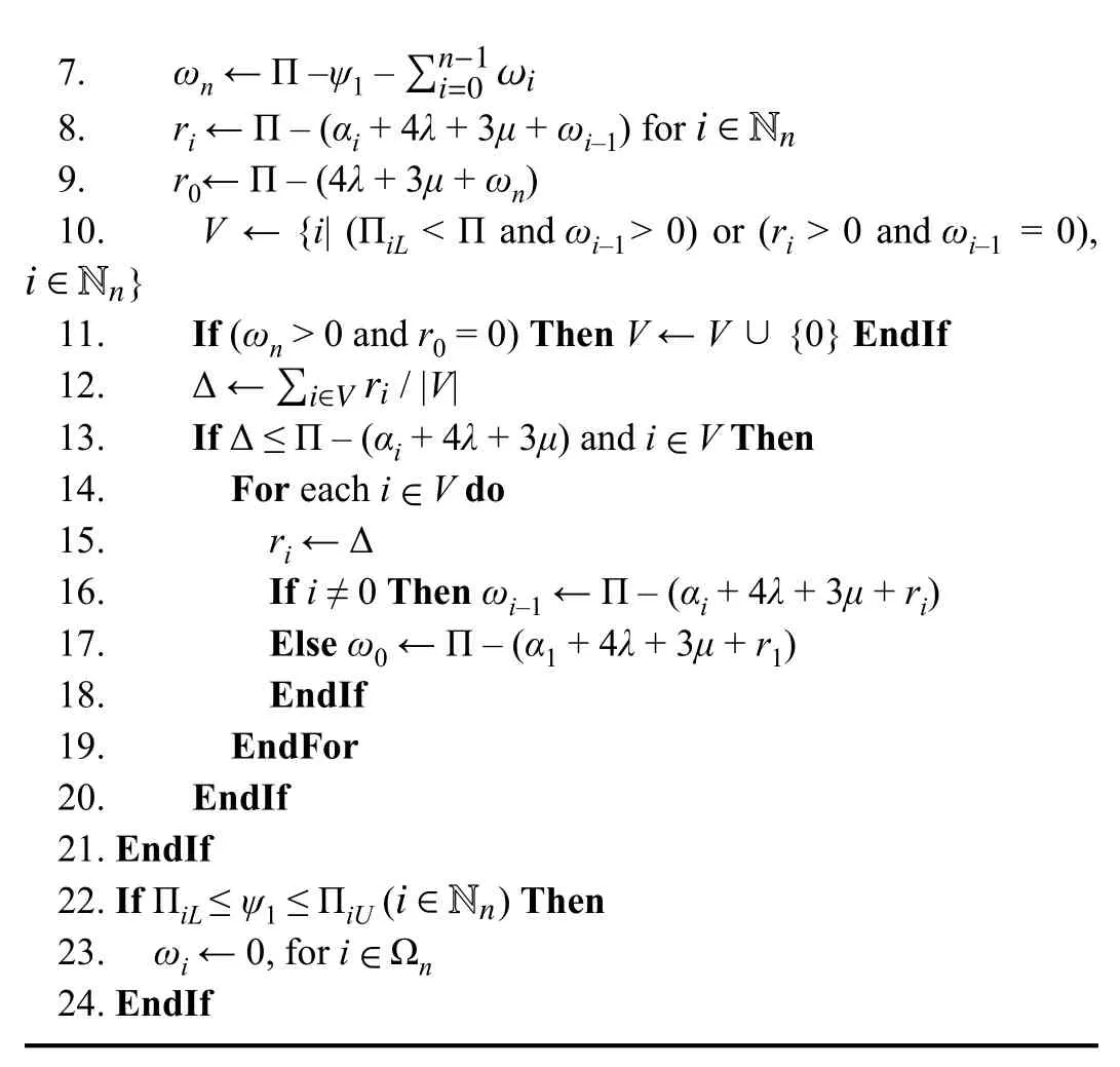
∑n?1 i=0 ωi 7. ωn ← Π –ψ1 –i ∈Nn 8. ri ← Π – (αi + 4λ + 3μ + ωi–1) for 9. r0← Π – (4λ + 3μ + ωn)i ∈Nn 10. V ← {i| (ΠiL < Π and ωi–1> 0) or (ri > 0 and ωi–1 = 0),}11. If (ωn > 0 and r0 = 0) Then V ← V ∪ {0} EndIf∑i∈V ri 12. Δ ← / |V|13. If Δ ≤ Π – (αi + 4λ + 3μ) and i V Then∈∈14. For each i V do 15. ri ← Δ 16. If i ≠ 0 Then ωi–1 ← Π – (αi + 4λ + 3μ + ri)17. Else ω0 ← Π – (α1 + 4λ + 3μ + r1)18. EndIf 19. EndFor 20. EndIf 21. EndIf i ∈Nn 22. If ΠiL ≤ ψ1 ≤ ΠiU ( ) Then 23. ωi ← 0, for i Ωn 24. EndIf∈
The following result is given to show the optimality of the obtained schedule via Algorithm 1.
Theorem 1:For single-arm cluster tools subject to wafer residency time constraints, if one of the two conditions: 1) Π ≤ΠiUand ψ1≤ Π,and 2)is satisfied, Algorithm 1 finds a schedule to reach the lower bound of cycle time and minimize total post-processing time.
Proof:Set the lower bound Π as the cycle time of a cluster toolψ= Π, or the minimal cycle time. Next, we check: a)whether a feasible schedule with cycle time Π can be constructed or not to meet the residency constraints under one of the given conditions; and b) minimize the post-processing time
By Line 5 of Algorithm 1, ifω0= Π – (α1+ 4λ+ 3μ) < Π–ψ1, thenτ1= Π – (4λ+ 3μ+ω0) =α1is minimized and[α1,α1+δ1]. Ifω0= Π –ψ1< Π – (α1+ 4λ+ 3μ),ω0is maximized because no more time than Π –ψ1can be assigned toω0. Then,τ1is minimized andτ1= Π – (4λ+ 3μ+ω0) = Π –(4λ+ 3μ) – (Π –ψ1) ≥ Π – (4λ+ 3μ) – (Π – (α1+ 4λ+ 3μ)) =α1,τ1= Π – (4λ+ 3μ+ω0) ≤ Π1U– (4λ+ 3μ+ω0) ≤ Π1U– (4λ+ 3μ) =α1+δ1.
By Line 6 of Algorithm 1, ifωi–1= Π – (αi+ 4λ+ 3μ) < Π–ψ1, thenτi= Π – (4λ+ 3μ+ωi–1) =αiis minimized andIfωi–1= Π –ψ1–≤ Π – (αi+ 4λ+3μ),ωi–1is maximized because no more time than Π –ψ1–can be assigned toωi–1. Then,τiis minimized andτi= Π – (4λ+ 3μ+ωi–1) ≥ Π – (4λ+ 3μ+ (Π – (αi+ 4λ+3μ))) =αi, andτi= Π – (4λ+ 3μ+ωi–1) ≤ ΠiU– (4λ+ 3μ+ωi–1) =αi+δi–ωi–1≤αi+δi.
Thus, wafer residency constraints are satisfied whenΩn) is set by Lines 5–7 of Algorithm 1 whileminimized. Then, Lines 8–20 intend to readjust the postprocessing time evenly for Steps inand0) or (ri> 0 andωi–1= 0),Furthermore, during the adjustment process,keeps unchanged.
If Δ ≤ Π – (αi+ 4λ+ 3μ)holds in Line 13, then, by Lines 16 and 17, we haveωi–1= Π – (αi+ 4λ+ 3μ+ Δ) ≥ Π –(αi+ 4λ+ 3μ+ Π – (αi+ 4λ+ 3μ)) = 0 (i≠ 0) andω0= Π – (α1+ 4λ+ 3μ+ Δ) ≥ Π – (αi+ 4λ+ 3μ+ Π – (αi+ 4λ+ 3μ)) = 0.Obviously, forri= Δ > 0 andri= Δ ≤ Π – (αi+ 4λ+ 3μ)≤ ΠiU– (αi+ 4λ+ 3μ) =δi.
So far, we can conclude that if one of the given conditions in this theorem is satisfied, Algorithm 1 can find a schedule that minimizes both the cycle time and wafer post-processing time. ■
By Lines 5–7, Algorithm 1 initially finds a schedule with both cycle time and wafer post-processing time being minimized. Lines 8–20 make efforts to readjust postprocessing time evenly for some steps. This adjustment can avoid unnecessarily excessive post-processing time, which is beneficial in improving the quality of the fabricated wafer.
In Algorithm 1, all the statements make calculations based on closed-form expressions. The number of iterations in the For-loop of Lines 14–19 cannot be greater thann. It is obvious that the computational complexity of Algorithm 1 is
Case 2:which implies that the workloads of the processing steps are unbalanced. In this case,Algorithm 2 is proposed to determine whether a feasible schedule can be found, and whether the lower bound of cycle time of the found schedule is reached.
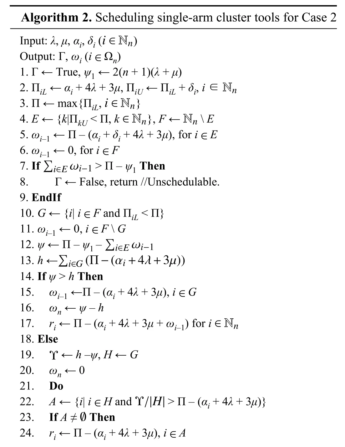
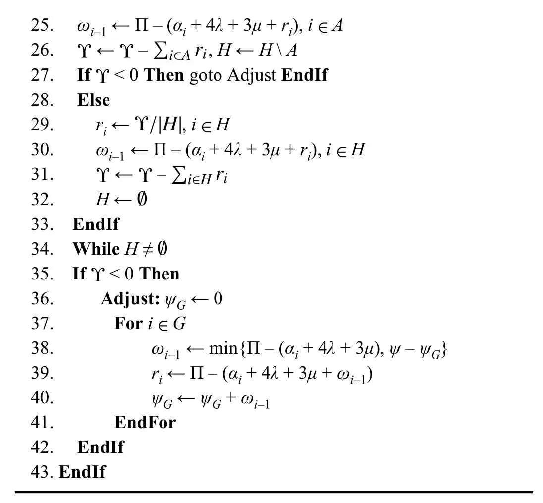
Algorithm 2. Scheduling single-arm cluster tools for Case 2 i ∈Nn Input: λ, μ, αi, δi ( )Output: Γ, ωi (i Ωn)1. Γ ← True, ψ1 ← 2(n + 1)(λ + μ)∈2. ΠiL ← αi + 4λ + 3μ, ΠiU ← ΠiL + δi, i ∈Nn i ∈Nn 3. Π ← max{ΠiL, }∈Nn Nn 4. E ← {k|ΠkU < Π, k }, F ← E 5. ωi–1 ← Π – (αi + δi + 4λ + 3μ), for i E∈∈6. ωi–1 ← 0, for i F∑i∈E ωi?1 7. If > Π – ψ1 Then 10. G ← {i| i F and ΠiL < Π}∈8. Γ ← False, return //Unschedulable.9. EndIf∈11. ωi–1 ← 0, i F G∑i∈E ωi?1 12. ψ ← Π – ψ1 –i∈G(Π?(αi+4λ+3μ))13. h ←∑14. If ψ > h Then 15. ωi–1 ←Π – (αi + 4λ + 3μ), i G 16. ωn ← ψ – h∈∈Nn 17. ri ← Π – (αi + 4λ + 3μ + ωi–1) for i 18. Else Υ 19. ← h –ψ, H ← G 20. ωn ← 0 21. Do∈ Υ/|H|22. A ← {i| i H and > Π – (αi + 4λ + 3μ)}?23. If A ≠ Then∈24. ri ← Π – (αi + 4λ + 3μ), i A
25. ωi–1 ← Π – (αi + 4λ + 3μ + ri), i A Υ Υ ∑i∈A ri 26. ← – , H ← H A∈27. If < 0 Then goto Adjust EndIf 28. Else Υ Υ/|H|∈29. ri ← , i H 30. ωi–1 ← Π – (αi + 4λ + 3μ + ri), i H Υ Υ ∑i∈H ri 31. ← –∈32. H ←33. EndIf?34. While H ≠Υ?35. If < 0 Then 36. Adjust: ψG ← 0∈37. For i G 38. ωi–1 ← min{Π – (αi + 4λ + 3μ), ψ – ψG}39. ri ← Π – (αi + 4λ + 3μ + ωi–1)40. ψG ← ψG + ωi–1 41. EndFor 42. EndIf 43. EndIf
Theorem 2:IfAlgorithm 2 can determine whether a feasible schedule exists. If it does,Algorithm 2 can find a schedule that minimizes both the cycle time and post-processing time.
Proof:By Line 4 of Algorithm 2, we haveFor Stepsi∈E, since the cycle time of every step must be identical to obtain a one-wafer cyclic schedule,ωi’s (i∈E) must be set by Line 5, which means thatωi’s (i∈E) have been maximized. Thus, byτi= Π – (4λ+ 3μ+ωi–1),τi’s (i∈E) are minimized.
Case A:ψ>h.
Case B:ψ≤h.
Lines 4, 12, 20, and 22 of Algorithm 2 present thatA= {i|iimplying that ΠiL< Π ≤ΠiUand> Π – (αi+ 4λ+ 3μ).
IfA≠> Π – (αi+ 4λ+ 3μ), then by Lines 24 and 25, we haveωi–1= Π – (αi+4λ+ 3μ+ Π – (αi+ 4λ+ 3μ))= 0 for StepsThus, by Line 24,ri= Π – (αi+ 4λ+ 3μ) ≥ΠiL– (αi+ 4λ+ 3μ) = 0,ri≤ ΠiU– (αi+ 4λ+ 3μ) =δi. By Line 27, ifi.e., there aretime units that can be assigned to the post-processing time at the steps inH. Ifholds, then it leads to a contradictory as follows. Ifthenh–ψ–orIf Line 27 is removed and allare set by this “do-while” loop in Lines 21–34, then4λ+3μ))?. Equation (1) and Lines 11, 12 and 20 implyThus,which is contradictory to the aforementionedbecause ofThereby, ifoccurs in Line 27, Lines 36–41 can resetωi–1’sBy Line 38, ifωi–1= Π – (αi+4λ+ 3μ) <ψ–ψG, thenri= Π – (αi+ 4λ+ 3μ+ωi–1) = 0 is minimized. By Line 38, ifψ–ψG< Π – (αi+ 4λ+ 3μ), then there areψ–ψGtime units available to be assigned toωi–1, orωi–1=ψ–ψGis maximized. Then,ri= Π – (αi+ 4λ+ 3μ+ωi–1) = Π – (αi+ 4λ+ 3μ+ψ–ψG) > Π – (αi+ 4λ+ 3μ+ (Π –(αi+ 4λ+ 3μ))) = 0 andri= Π – (αi+ 4λ+ 3μ+ψ–ψG) ≤ Π –(αi+ 4λ+ 3μ+ 0) ≤ ΠiU– (αi+ 4λ+ 3μ) =δibecause ofψ–ψG≥ 0.
Algorithm 2 deals with the situation ofwhich indicates that some steps have heavier workloads than others. Given the lower bound of cycle time, robot waiting timeis assigned in advance. After its assignment,one can decide if the cluster tool is schedulable as done in Line 7. Then we compare the workload of the robot with those of the processing steps, and if the robot is fast enough, the post-processing time can be minimized to be zero, which is implemented in Lines 15–17. If not, there is non-zero postprocessing time for StepsThen, the sum of them, i.e.,is minimized andis set evenly, as implemented in Lines 19–42.
In Algorithm 2, all the statements make calculations based on closed-form expressions. The count of iterations in Lines 21–34 and 37–41 cannot be greater thann. It is obvious that the computational complexity of Algorithm 2 isO(n).
IV. Examples
In this section, we demonstrate how to apply the proposed method to find schedules for bi-objective problems. The time unit is seconds and is omitted thereafter. Letdenote the post-processing time if a cluster tool is scheduled by a conventional method that does not consider minimizing the post-processing time.
Example 1:There are four steps in a single-arm cluster tool where every step is equipped with one PM. The robot waiting time is found by Algorithm 1. The activity time, wafer residency time constraints and the post-processing time at each step (excluding Step 0 or LLs) is given as follows:
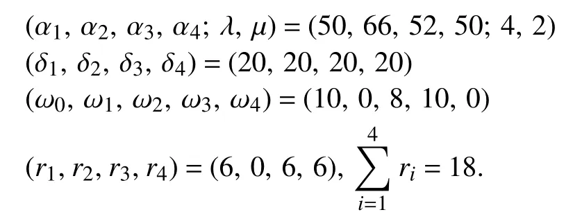
If the existing algorithms in [32] are applied to find an optimal schedule, we obtain post-processing time as= (16, 0, 14, 16) andBy our algorithm, the total post-processing time is decreased by 60.9%. Furthermore,is evenly distributed among the four steps.
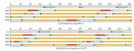
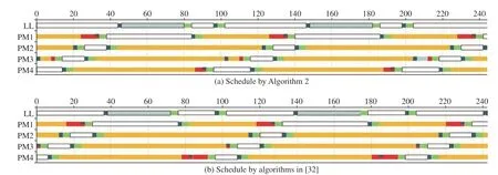
The schedules obtained by Algorithm 1 and previous work in [32] are shown by Gantt charts in Fig. 2 . The postprocessing time is indicated by red bars in Figs. 2–4.
Example 2:There are four steps in a single-arm cluster tool where every step is equipped with one PM. It satisfiesThe schedulability condition≤ Π –ψ1holds. Thus, the robot waiting time are found by Algorithm 2. The activity time, wafer residency time constraints, and the post-processing time at each step(excluding Step 0 or LLs) are
Case 1:ψ>h.
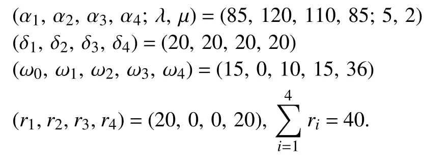
If the algorithms in [32] are applied to find an optimal schedule, we have= (20, 0, 10, 20) andThe total post-processing time is decreased by 20%. The schedules obtained by Algorithm 2 and previous work in [32] are shown by Gantt charts in Fig. 3.
Case 2:ψ The algorithms in [32] find an optimal schedule with= (10, 0, 2, 14) andThe total postprocessing time is decreased by 30.8%. The schedules obtained by Algorithm 2 and previous work in [32] are shown by Gantt charts in Fig. 4. We conclude that the proposed algorithms can find the same optimal-cycle-time schedule as the existing ones [32] but with significantly reduced post-processing time. Fig. 2. Gantt chart for Example 1. Fig. 3. Gantt chart for Case 1 of Example 2. Fig. 4. Gantt chart for Case 2 of Example 2. Cluster tools are extensively adopted for wafer fabrication equipment in the semiconductor manufacturing industry.Wafers are fabricated in a complex chemical reaction environment where there are mixed gases and hightemperature heat. Characteristics of new materials and highquality chips require that after their processing is completed,they should leave the processing chamber as soon as possible.The existing research ensures that post-processing time does not exceed the upper limit only. In order to obtain high-quality integrated circuits with advanced process control, this work considers two optimization objectives for single-arm cluster tools subject to wafer residency time constraints. It not only considers the maximization of the throughput but also minimizes wafer post-processing time in processing chambers. When the throughput is maximized and wafer residency time constraints are satisfied, we make efforts to shorten wafer sojourn time after a wafer is processed to avoid uneven post-processing time among the processing steps.Therefore, the obtained schedules are significantly better for fabricating high-quality wafers which are not seen in the existing reports to our best knowledge. In the future, we intend to answer how to schedule multi-cluster tools with multiple optimization goals.
V. Conclusions

 IEEE/CAA Journal of Automatica Sinica2020年2期
- IEEE/CAA Journal of Automatica Sinica的其它文章
- Parallel Reinforcement Learning-Based Energy Efficiency Improvement for a Cyber-Physical System
- Flue Gas Monitoring System With Empirically-Trained Dictionary
- Unified Smith Predictor Based H∞ Wide-Area Damping Controller to Improve the Control Resiliency to Communication Failure
- Optimal Neuro-Control Strategy for Nonlinear Systems With Asymmetric Input Constraints
- Adaptive Output Regulation of a Class of Nonlinear Output Feedback Systems With Unknown High Frequency Gain
- A Method for Deploying the Minimal Number of UAV Base Stations in Cellular Networks
