A low-jitter self-triggered spark-discharge pre-ionization switch: primary research on its breakdown characteristics and working mechanisms
Tianchi WANG (王天馳), Yingchao DU (杜應(yīng)超), Wei CHEN (陳偉),Junna LI (李俊娜), Haiyang WANG (王海洋), Tao HUANG (黃濤),Linshen XIE (謝霖?zé)?, Le CHENG (程樂) and Ling SHI (石凌)
1 Key Laboratory of Particle & Radiation Imaging (Tsinghua University), Ministry of Education, Beijing 100084, People’s Republic of China
2 Department of Engineering Physics, Tsinghua University, Beijing 100084, People’s Republic of China
3State Key Laboratory of Intense Pulsed Radiation Simulation and Effect, Northwest Institute of Nuclear Technology, Xi’an 710024, People’s Republic of China
4 State Key Laboratory of Electrical Insulation and Power Equipment, Xi’an Jiaotong University, Xi’an 710049, People’s Republic of China
Abstract MV pulsed switch plays a key role as the transfer switch in large electromagnetic pulse simulators.To broaden the range of self-triggering time, a novel spark-discharge pre-ionization switch,in which the main gap electric field is superposed at the trigger gap to let the electrons in its spark channel also become initial electrons, is proposed and tested.The design idea is: as electrons in the spark channel of the trigger gap always exist after its breakdown, the injection time of pre-ionization should have a more negligible effect on reducing the switch jitter.The experiment results under pulses with a rise time of ~100 ns support the above assumptions.When the operating voltage is from ~300 to ~800 kV and the self-triggering time is ~45% to~75% of the peak time, the breakdown time delay jitter is less than 2 ns, and the breakdown voltage jitter is smaller than 1.25%.Under specific self-triggering time, the breakdown time delay jitter is less than 1.5 ns, and the breakdown voltage jitter is smaller than 0.8%.
Keywords: gas switch, self-triggering, pre-ionization, jitter, nanosecond pulse
1.Introduction
In the MV bipolar pulse generator for electromagnetic pulse(EMP) simulator [1], two primary pulses with hundrednanosecond rise time need compression and superposition,which requires low-jitter pulsed transfer switches [1, 2].To meet the requirement of the output waveform and obtain a high energy transfer efficiency,the switch should break down near the peak time of input pulses,which adds the difficulty of reducing the switch jitter due to a relatively small du/dt near the peak time [3].The time jitters of laser-triggering and electrical-triggering switches can be reduced to 1–3 ns [4–8],but external sources are required.To reduce the cost and complexity, self-triggering methods like corona stabilization or UV-illumination are explored [9–14].
Figure 1(a) demonstrates a typical configuration of the UV-illumination switch[11].As the reduced electric field E/p is about 200–300 kV cm?1·MPa?1in the switch, statistical time delay mainly contributes to the jitter[15].The statistical time delay jitter is determined by the coordination of the E/p and generating rate of initial electrons.Because initial electrons are supposed to be generated through photoemission[12] with low efficiency of no more than 1/100 [16], and FWHM of the UV-illumination generated by trigger gap discharge is generally less than 15 ns[12],the triggering time,which is determined by the voltage division ratio between the main gap and trigger gap, must be adjusted carefully.Figure 1(b) indicates that the effectiveness of UV-illumination varies dramatically as the ratio changes [17, 18].The time jitter increases as the ratio decreases (earlier triggering time), and the switch might fail to break down at the front edge,which seriously threatens the insulation.Besides,larger time jitter of the trigger gap under a larger voltage division ratio might also restrict the time jitter [18].It needs a large number of trials to determine an optimized ratio.Moreover,the resistors for voltage division might change as the operating time extends, which brings on more trouble.

Figure 1.Typical configuration (a) and breakdown characteristics of the UV-illumination switch (b) [17, 18].
Inspired by the low-jitter plasma-jet triggered switch operating under a low working coefficient [19], a low jitter spark-discharge pre-ionization switch is proposed.The trigger gap configuration is adjusted to let the electrons in the spark channel of the trigger gap also become initial electrons.It is proved that the self-triggering time has relatively less influence on the time delay jitter,which can be less than 2 ns as the 0%–100%rise time of input pulse is 100 ns and the operating voltage is from ~300 to ~800 kV.The working mechanism of pre-ionization is also preliminarily analyzed, which supports the previous assumption.
2.Experimental setup
2.1.Switch structure
To let the electrons in the spark channel of the trigger gap drift towards the main gap anode, the main gap electric field should cover the trigger gap.This can be implemented by enlarging the hole in the trigger plane.In the UV-illumination switch,the diameter of the trigger plane hole is about 15 mm.While in the spark-discharge pre-ionization switch,if we hope the main gap electric field at the trigger gap to be as high as in other regions as possible, the main gap discharge path will certainly cover the trigger electrodes.Therefore, in the proto shown in this paper,the trigger plane hole is simply enlarged to its maximum value (112 mm) to ensure a high main gap electric field at the trigger gap.
Figures 2(a)and(b)compare the trigger electrode planes of UV-illumination switch and spark-discharge pre-ionization switch.Similarly,the trigger anode(stainless steel)is fixed on the trigger plane, and the trigger cathode (tungsten) is insulated from the trigger plane (stainless steel) by ceramic bushing.The trigger gap distance is set as 1 mm.The main electrodes are also made of stainless steel.
Figures 2(c) and (d) demonstrate the appearances of the UV-illumination switch and spark-discharge pre-ionization switch.In the former switch,the main gap is divided into two sub gaps by the trigger plane.In the latter switch, the main gap is integrated,and the current through the main gap might cause some slight erosion of trigger gap electrodes.Nevertheless, the trade-off is acceptable in a low-current singlepulse mode operated generator for EMP simulator, the max peak current through the transfer switch is only about~10 kA,and the duration time is no more than 1 μs,while the low jitter characteristic is foremost.
Figure 2(e)is an equivalent circuit of the spark-discharge pre-ionization switch (a four-electrode switch).C1–C4are equivalent capacitances between trigger gap electrodes and main gap electrodes.Ctriggeris the coaxial structural capacitance of the trigger gap.R1, Rtrigger, and R2are the parallel resistors connecting the four electrodes for voltage division.The trigger anode is equipotential to the trigger plane in figure 2(b), while there is a potential difference (the trigger gap voltage) no more than 20 kV between trigger anode and trigger cathode through the ceramic bushing.In experiments,R1= R2≈ 24.5 kΩ, which is much smaller than the capacitive resistance of C1–C4(~318 kΩ).The capacitive resistance of Ctriggeris ~13 kΩ, and Rtriggercan be adjusted.Therefore, the corresponding voltage division ratios between the main gap and trigger gap are decided by the capacitance–resistance coupling structure.When the trigger gap breaks down earlier than the main gap, pre-ionization is injected.
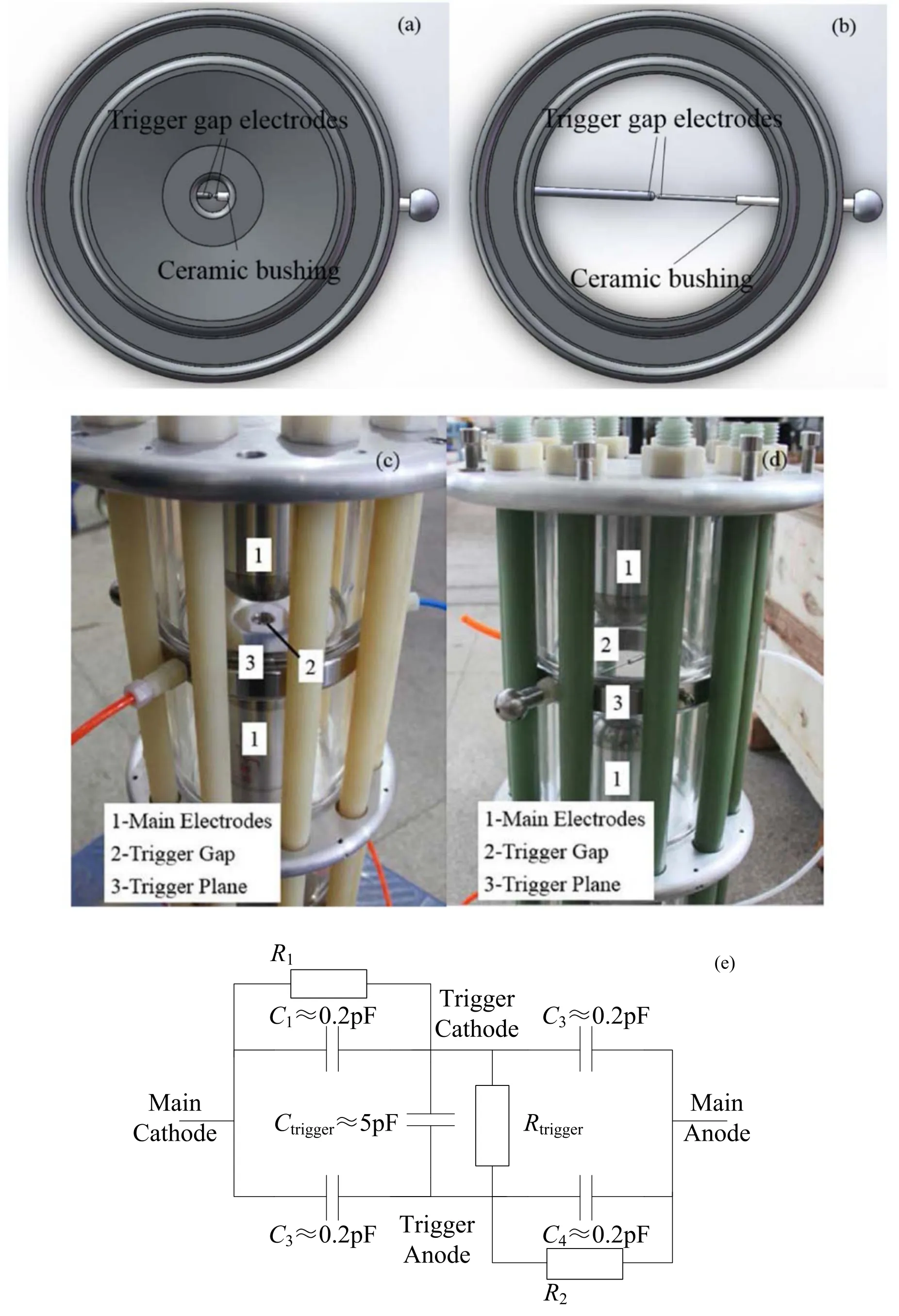
Figure 2.Trigger electrode planes and appearances of the UV-illumination switch (a) (c) and the spark-discharge pre-ionization switch (b)(d), the equivalent circuit of the spark-discharge pre-ionization switch before its breakdown (e).
Figure 3 gives simulated electric field distributions of the two switches.The electric potentials on the cathode, the trigger plane, and the anode are set as ?1000 kV, ?500 kV,and 0 kV,respectively.In the UV-illumination switch,due to the shielding effect of the trigger plane,the main gap electric field strength at the trigger gap is only ~50 kV cm?1(average electric field is ~166.7 kV cm?1).It is hardly possible for the electrons in the spark channel of the trigger gap to drift towards the main gap anodes during the time duration of input pulses (~200 ns) [17].

Figure 3.Electric field distributions in the UV-illumination pre-ionization switch (a) and the spark-discharge pre-ionization switch (b).
In the spark-discharge pre-ionization switch, the electric field strength at the trigger gap is ~110 kV cm?1(average electric field is 142.9 kV cm?1), so the shielding effect is eliminated to a great degree.Consequently, electrons in the trigger gap’s spark channel will participate in the switch breakdown process, which will extend the duration of preionization due to a sustaining arcing trigger gap.
2.2.Experimental platform
Figure 4 demonstrates the equivalent circuits of the experimental platform and the trigger gap before breakdown.The 0%–100% rise time of the pulses generated by the Marx generator is ~100 ns(10%–90%rise time is ~60 ns),and the output voltage amplitude is from ~200 to ~800 kV.The preionization switch is the pulsed switch in the platform.The charging current of transfer capacitor Ctand the switch current through the pulsed switch are measured by resistors r1and r2,respectively.The voltage on Ctcan be obtained by the integral of its charging current.

Figure 4.Equivalent circuit of the experimental platform.
2.3.Data definition and processing
To explain the data definition, figure 5 demonstrates the simulated waveforms.Figure 5(a)shows the waveforms with the switch’s breakdown.The theoretical breakdown time delay is the time difference between t = 0 and the starting point of the switch current (also the turning point of the charging current of Ct).However, t = 0 and the starting/turning point are difficult to recognize in practice.To unify the reading criterion, the breakdown time delay is defined as the 10% peak time of the switch current subtracts the 10%peak time of the voltage on Ct.The voltage waveform on Ctcan be taken as that on the pulsed switch before its breakdown(shown in figure 5(b)).
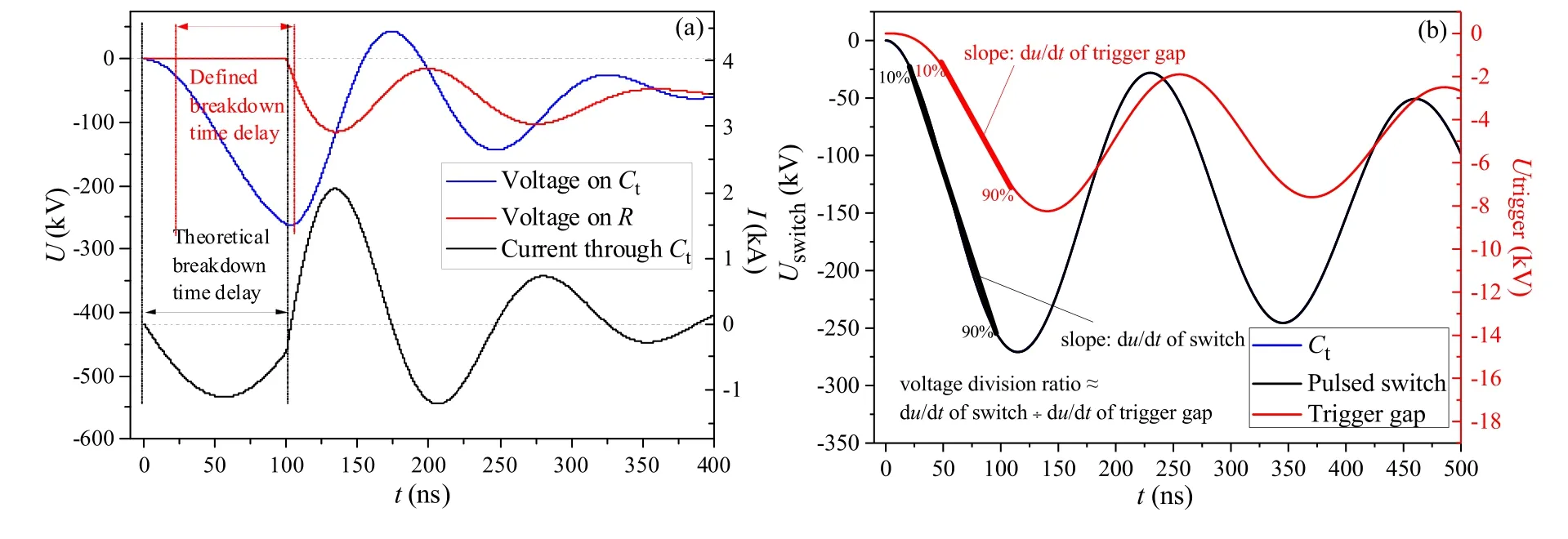
Figure 5.Definition of breakdown time delay (a) and voltage division ratio (b).
The breakdown efficiency is estimated by the ratio between the 10% and 90% front edge of voltage on Ctunder the experiment condition and the 10%–90% front edge when the pulsed switch is disconnected(60 ns).When the measured 10%–90% front edge is 57 ns, the switch is considered to break down at ~95% peak time.The breakdown voltage is regarded as the peak voltage on Ctas only breakdown cases near the peak time are concerned in the experiments.
Figure 5(b) shows the voltage waveforms on the switch and its trigger gap without its breakdown.The trigger gap shares a portion of the switch voltage and is adjusted to break down during 10%–90% front edge to maintain low jitter, in which the voltage can be regarded as a ramp.Therefore, to briefly describe the voltage portion shared on the trigger gap,we define a simple concept

in equation(1),du/dt is defined as the rising speed of pulsed voltage during 10%–90% front edge.The voltage division ratio is determined by the capacitance and resistance parameters in figure 2(e).As the capacitance parameters are fixed with a specific switch structure, and R1and R2are also fixed to restrict the leak current,the ratio can mainly be adjusted by the parallel resistor Rtrigger.It is necessary to note that the voltage division ratio as an engineering parameter only reflects the rough voltage division relation between the switch and its trigger gap.The trigger gap’s breakdown time still needs to be estimated by the simulated waveforms.This is mainly because the trigger gap voltage waveform has a phase difference with the main gap (figure 5(b)).
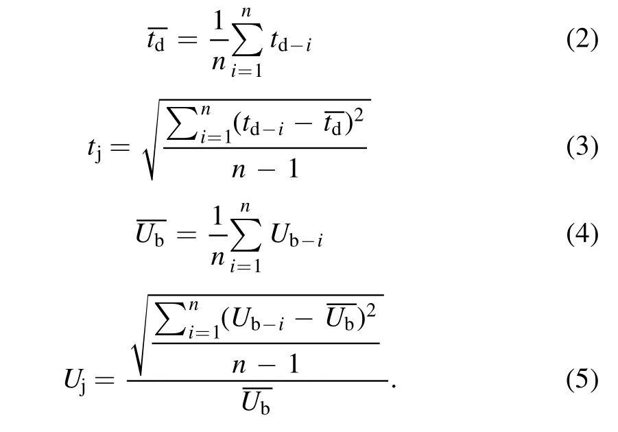
The electrodes are cleaned by alcohol, and the switch is fired for more than 200 shots before experiments.The working medium is nitrogen, and the operating voltage is from ~300 to ~800 kV due to the capacity of the Marx generator.1–4 conditions are tested under each pressure to adjust the switch to break down near ~95% peak time.Fifty shots are carried out under each condition.The mean breakdown time delaytime delay jitter tj, mean breakdown voltagepercentage breakdown voltage jitter Ujare calculated using equations (2)–(5).n is the number of effective data,td-iand Ub-iare the measured time delay and breakdown voltage of the ith trial, respectively.
3.Result
3.1.Overall breakdown characteristics
Figures 6–8 demonstrate the breakdown time delay/voltage and their jitters under three voltage division ratios.Considering that a self-breakdown switch cannot break down stably at the pulse front edge near the peak time[17],the preionization can be defined as fully effective if the switch can break down stably at the pulse front edge.While the switch breaks down at the back edge or misfires during the whole pulse, the pre-ionization is not fully effective.
In figure 6, Rtriggerin figure 2(e) is removed, and the voltage division ratio is about 4.63, which means the trigger gap shares a large portion of the switch voltage and breaks down very early.The mean breakdown time delay is from~70 to ~100 ns, so the switch breaks down near the peak time.The breakdown time delay jitter is around 1–2 ns under all conditions, which indicates that the pre-ionization is effective even it is injected into the switch gap very early.The breakdown voltage is from ~300 to ~800 kV as the gas pressure is adjusted from 0.1 to 0.5 MPa,and the voltage jitter is less than 1% under all cases.
In figure 7, Rtriggerin figure 2(e) is 4.5 kΩ, and the voltage division ratio is about 14.33.Therefore, the trigger gap breaks down later than in the formal case.The breakdown time delay is between ~70 and ~90 ns, so the switch also breaks down near the peak time.The time delay jitter is less than 2 ns under all conditions and can be less than 1.5 ns by adjusting du/dt slightly.The breakdown voltage is from~350 to ~850 kV as the gas pressure varies from 0.1 to 0.4 MPa,which is higher than the formal case under the same gas pressure,and the voltage jitter is less than 0.8%under all conditions.
In figure 8, Rtriggerin figure 2(e) is 2.2 kΩ, and the voltage division ratio is about 24.96,which means the trigger gap will break down further later.The breakdown voltage is from ~400 to ~800 kV as the gas pressure is adjusted from 0.1 to 0.4 MPa.However,under 0.1 MPa,the breakdown time delay jitter is larger than 6 ns, and the breakdown voltage is near 400 kV, which indicates the pre-ionization is probably ineffective due to the late injection.The switch can break down stably near the peak time when the gas pressure varies from 0.2 to 0.4 MPa, the breakdown time delay is from ~70 to ~95 ns, and its jitter is from ~1 to ~2 ns.When the preionization is effective, the voltage jitter is from ~0.5% to~1.25%,which is slightly larger than those for the two cases above.
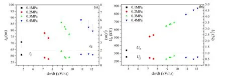
Figure 7.Breakdown time delay (a) and voltage (b) jitters when voltage division ratio =14.33.
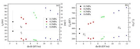
Figure 8.Breakdown time delay (a) and voltage (b) jitters when voltage division ratio =24.96.
To realize the synchronization in the bipolar generator for an EMP generator, the time difference of two transfer switches should be less than 10 ns [1].Equivalently, the one sigma time jitter of a single switch should be smaller than 2 ns, which can be basically achieved by adopting the sparkdischarge pre-ionization switch.
3.2.Influence of the injection time of pre-ionization
The spark-discharge pre-ionization switch is proposed to diminish the impact of pre-ionization’s injection time on the time delay jitter.As the breakdown time delay jitter is less than 2 ns and the breakdown voltage jitter is less than 1.25%under three ratios,pre-ionization can be seen as effective,and the influence of pre-ionization’s injection time is not obvious.However, there are still slight differences under different voltage division ratios.To show these directly,the data when the switch breaks down near ~95% peak time are demonstrated in figure 9.
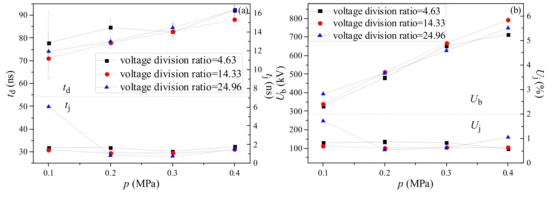
Figure 9.Breakdown time delay (a) and voltage (b) jitters under different voltage division ratios when the switch breaks down near ~95%peak time.
As the switch is adjusted to break down near the peak time of the input pulse, the breakdown voltage jitter is generally less than 1% when the pre-ionization is effective and less than 2% even the pre-ionization is ineffective.So the differences are more revealed by the time delay and jitter.
Table 1 demonstrates the estimated ttrand E(ttr)/Epeakbased on experimental results, the breakdown voltage of the trigger gap is set as 8 kV,11 kV,14 kV,and 17 kV when the gas pressure is 0.1 MPa, 0.2 MPa, 0.3 MPa, and 0.4 MPa,respectively.It indicates that the pre-ionization is effective when the trigger gap breaks down at ~45% to ~75% of the peak electric field in this switch.While in the UV-illumination switch, the pre-ionization is proved to be invalid when the trigger gap breaks down at ~45% to ~55% of the peak electric field under gas pressure from 0.1 to 0.3 MPa [17].

Table 1.Estimated injection time of pre-ionization (ttr) and E(ttr)/Epeak.
When the gas pressure varies from 0.2 to 0.4 MPa, the breakdown time delay jitter becomes slightly smaller as the pre-ionization injection time is postponed.It is explicable because the initial electrons and electric field have better coordination when the initial electrons are generated under a higher electric field.
4.Discussion
4.1.The working mechanism of pre-ionization
In a UV-illumination switch,electrons in the spark channel of the trigger gap cannot drift out, so initial electrons are generated by photoemission or photoionization.While in the spark-discharge pre-ionization switch, the electrons in the spark channel should be considered, but which electrons initiate the breakdown still needs analysis.The crucial parameters are the duration of the UV optical pulse and the main gap electric field when the trigger gap breaks down.
As the generating rate of photoelectrons is proportional to the illumination intensity [20] and the illumination intensity is proportional to the discharge current [21], figure 10 demonstrates a simulated current waveform through the trigger gap under 0.1 MPa, which is a damped oscillatory wave with an FWHM of ~5 ns.The current will be smaller than its 10%peak value after 15 ns.Because the efficiency of UV-illumination is less than 1% [16], its effective duration(during this time, initial electrons can be generated through photoemission or photoionization) should be closely related to the duration time of discharge current.
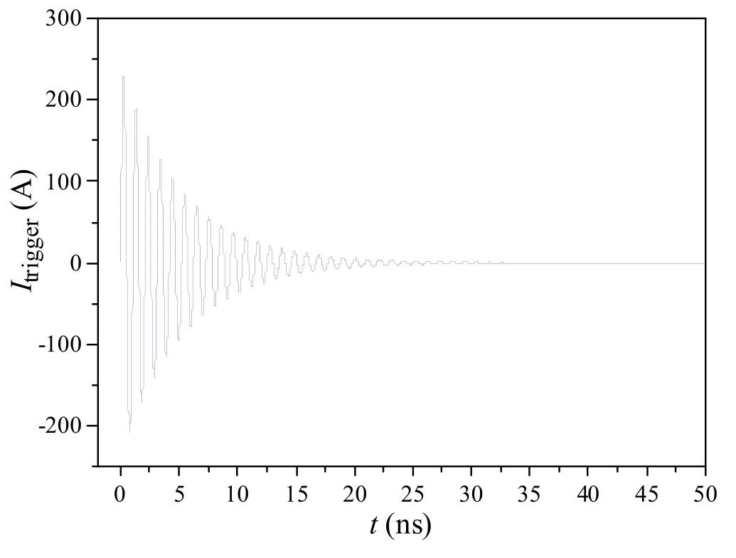
Figure 10.A typical current waveform through the trigger gap(under 0.1 MPa).
However, it is difficult to quantitatively calculate the duration and judge when the UV-illumination will be invalid due to the damping of the trigger discharge current.For further analysis, the effectiveness of pre-ionization under different injection times in the UV-illumination switch and spark-discharge pre-ionization switch should be compared.
Figure 11 demonstrates electric field strength in two switches at t = ttrand the breakdown time, in which the breakdown time of the trigger gap can be estimated by the measured data(the estimated value in the spark-discharge preionization switch might be slightly shorter than the actual value due to the main gap electric field superposed at the trigger gap [22]).
Figure 11(a) compares the electric field at t = ttrand the effectiveness of two types of pre-ionization.The spark-discharge pre-ionization is fully effective when the gas pressure is 0.1 or 0.2 MPa, while only UV-illumination is partly effective under a similar electric field.When the gas pressure is 0.3 or 0.4 MPa, the spark-discharge pre-ionization is fully effective even the electric field at t = ttris lower than that leading to a partly effective pre-ionization in the UV-illumination switch.Therefore, electrons in the trigger gap’s spark channel may participate in the breakdown process of the spark-discharge pre-ionization switch.It should be noted that the UV-illumination seems to be fully effective when the electric field at t = ttris lower under 0.3 and 0.4 MPa instead,it is just because there is no back-edge breakdown or misfire phenomenon observed, while the time jitter under these two conditions is also larger than 2.5 ns, which means that the effectiveness of UV-illumination pre-ionization is not good enough.
Figure 11(b) compares the breakdown electric fields.Like the dash lines indicate, the mean electric field in the spark-discharge pre-ionization switch is always higher than that in the UV-illumination switch and is more close to the maximum electric field in the UV-illumination switch.However, the field enhancement factors in the two switches are both about 1.5.As the breakdown in the UV-illumination switch is most likely to be initiated at the cathode surface(where the electric field is the strongest) [12], the breakdown mechanisms in the spark-discharge pre-ionization switch might be different.However, the pre-ionized breakdown process is rather complicated, the above assumption still needs direct evidence.
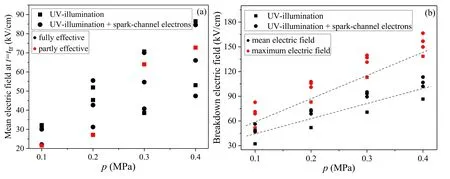
Figure 11.The electric field strength in two switches at t = ttr (a) and the breakdown time (b).
4.2.Influence factor of the time delay
The breakdown time delay of the spark-discharge pre-ionization switch shows a strong correlation with the breakdown electric field.The design idea assumes that the initial electrons will always exist as they are generated and will be effective when the electric field reaches the static breakdown electric field (when the trigger gap breaks down early) or the trigger gap breaks down.To compare the assumption with the slight difference under three voltage division ratios in the experiments, the effective time of initial electrons (ts) is calculated.Under the same electric field, the formative time delay makes little difference,so the characteristic of tdcan be mainly revealed by the characteristic of ts.ttris already estimated in table 1.The mean static breakdown electric field Es(kV cm?1)is calculated by(6),in which p is the gas pressure in MPa and d is the gap distance in cm [23]

Figure 12 demonstrates the estimated tsand experimental td.It is observed that the change rule of experimental tdis the same as the estimated ts.Under two smaller voltage division ratios, ttris smaller than 36 ns, at t = ttr, the electric field in the gap is not high enough to initiate the breakdown, so tsis the time when the electric field reaches Es.When the ratio is 14.33, the operating voltage is a little higher, so it takes less time for the electric field to reach the Es, which leads to a shorter ts.When the ratio increases to 24.96,tsis close to ttror even early than ttr, tsis also longer due to lower operating voltage,which leads to a longer td.In general,the design idea is roughly correct,and the injection time of pre-ionization has a negligible influence.
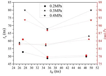
Figure 12.Estimated ts and experimental td under different ttr.
4.3.Failure mechanism of pre-ionization under large voltage division ratio
However, it requires an explanation that the pre-ionization is nearly ineffective under 0.1 MPa when the voltage division ratio is 24.96.The radial electric field might be the cause.As figure 3 indicates,the electric field at the trigger gap(a radial electric field for the trigger gap) is comparable to the mean electric field in the switch gap due to a larger hole in the trigger plane.
Figure 13 demonstrates the diagram of electric field components at the trigger gap and the comparison of estimated axial and radial electric fields under different voltage division ratios.Eaxialis the average electric field of the trigger gap, Eradialis the main gap electric field supposed at the trigger gap.Figure 13(b) indicates that the rising speed and absolute value of Eaxialwill increase as the voltage division ratio decreases.When the voltage division ratio is 4.63,Eaxial/Eradialincreases from 3.53 to 7.81 as t is from 10 to 50 ns, the Eaxialis the dominant component.When the ratio increases to 14.33, Eaxial/Eradialis from 2.64 to 4.76.When the ratio further increases to 24.96, Eaxial/Eradialis from 2.05 to 3.07, Eradialaccounts for about 31%–45% of the total electric field, which will definitely influence the breakdown process of the trigger gap.A simulation result indicates that the breakdown time delay might increase more when Eradialis stronger due to the radial drift of electrons towards the main gap anode[22].As the average breakdown electric field of the trigger gap without radial electric field is measured to be about 80 kV cm?1under 0.1 MPa, the breakdown time delay should be less influenced when the ratio is 4.63 or 14.33.While the ratio is 24.96, the actual breakdown time of the trigger gap might be more behind the estimated time.The preionization might be ineffective if the trigger gap breaks down after the peak time.In summary, under a large range of voltage division ratios, the breakdown jitter will not be significantly influenced by the injection time of pre-ionization,but the ratio should not be too large to prevent the invalidation of pre-ionization.
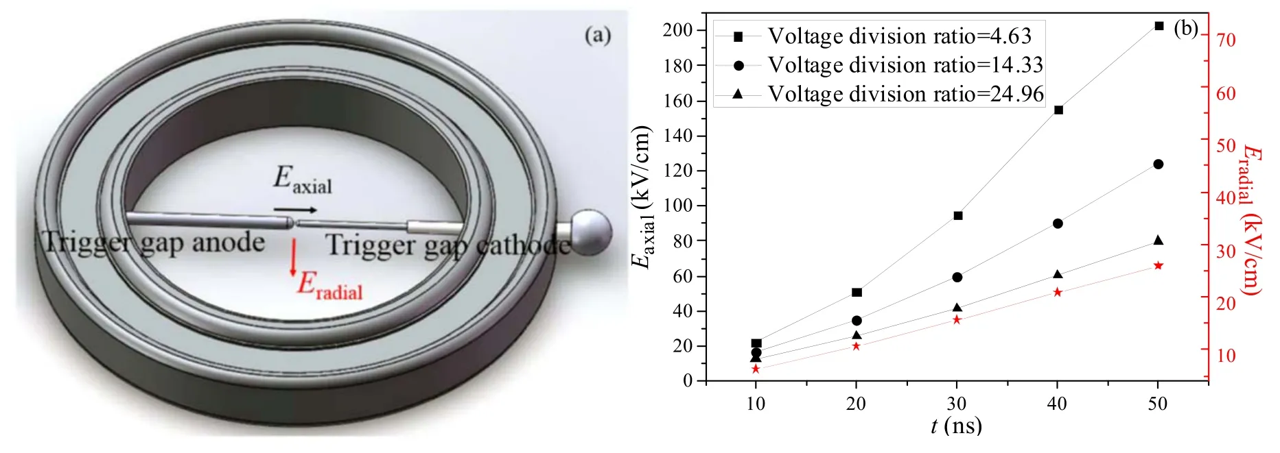
Figure 13.Electric field components at the trigger gap (a) and comparison of Eaxial and Eradial when p = 0.1 MPa and Umax = 350 kV.
5.Conclusions
First, in the spark-discharge pre-ionization switch, the preionization injection time has a more negligible effect on the switch jitter.When the operating voltage is from ~300 to~800 kV, and the pre-ionization is injected at ~45% to~75%of the peak time,the time delay jitter is less than 2 ns,and the breakdown voltage jitter is smaller than 1.25%.Under specific injection time, the time delay jitter can be less than 1.5 ns, and the breakdown voltage jitter can be smaller than 0.8%.The operating electric field mainly determines the mean breakdown time delay because the initial electrons always exist due to the sustaining arcing of the trigger gap after its breakdown.
Second, this switch’s mean breakdown electric field is 1.2–1.5 times that of the UV-illumination switch under the same gas pressure.Moreover, the spark-discharge pre-ionization is more effective than only UV-illumination under the same or lower electric field.These indicate that the electrons in the trigger gap spark channel are very likely to become the initial effective electrons as supposed.Despite this, it still needs direct evidence.
Besides,the supposed main gap electric field might delay the breakdown time of the trigger gap, which further brings about a failure of pre-ionization and large jitter under a large voltage division ratio between the main gap and trigger gap.The breakdown characteristics of the trigger gap with a superposed radial electric field also need further analysis.
ORCID iDs
 Plasma Science and Technology2021年11期
- Plasma Science and Technology的其它文章
- Influence of magnetic filter field on the radiofrequency negative hydrogen ion source of neutral beam injector for China Fusion Engineering Test Reactor
- Investigation on current loss of high-power vacuum transmission lines with coaxial-disk transitions by particle-in-cell simulations
- A calculation model for breakdown time delay and jitter of gas switches under hundred-nanosecond pulses and its application in a self-triggered pre-ionized switch
- Study of tetracycline removal and saturated resin regenerated by dielectric barrier discharge plasma
- Experimental study on the parameter optimization and application of a packed-bed dielectric barrier discharge reactor in diesel particulate filter regeneration
- Time-resolved spectroscopy of collinear femtosecond and nanosecond dual-pulse laser-induced Cu plasmas
