Influence of anode temperature on ignition performance of the IRIT4-2D iodine-fueled radio frequency ion thruster
Xinghua ZHANG(張興華),Zhenhua ZHANG(張振華),Shaoxia JIA(賈少霞), Ting JIN (金婷), Jinghua YANG (楊景華), Long LI (李龍),Fangfang LIU (劉芳芳), Yong CAI (蔡勇) and Jian CAI (蔡建)
1 Institute of Microelectronics,Chinese Academy of Sciences,Beijing 100029,People’s Republic of China
2 Suzhou Nano-Space Dynamics Technology Co.Ltd, Suzhou 215000, People’s Republic of China
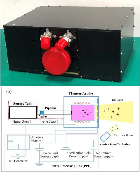
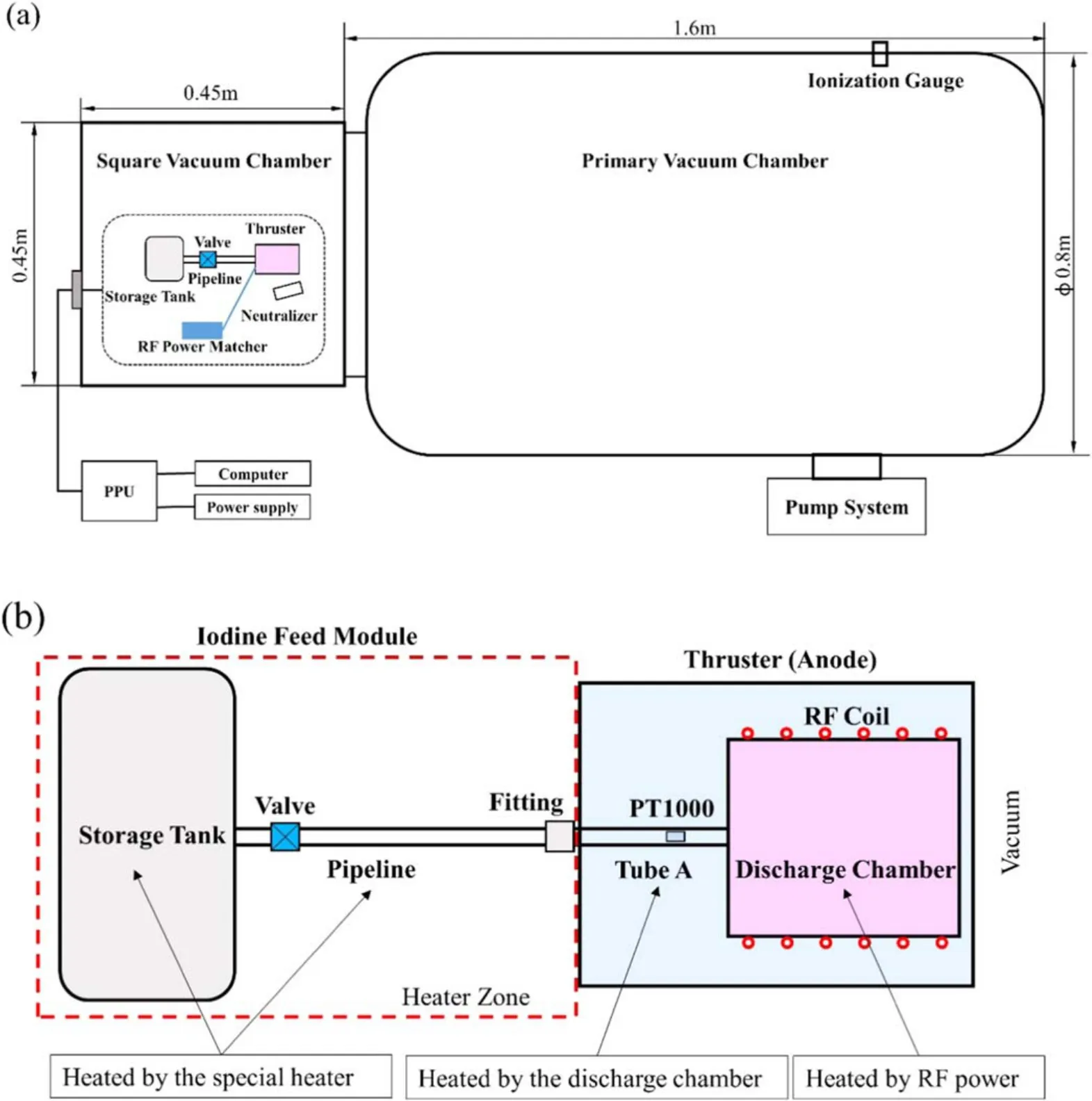
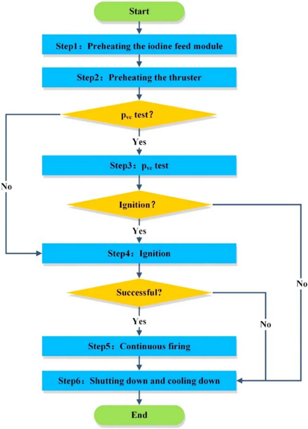
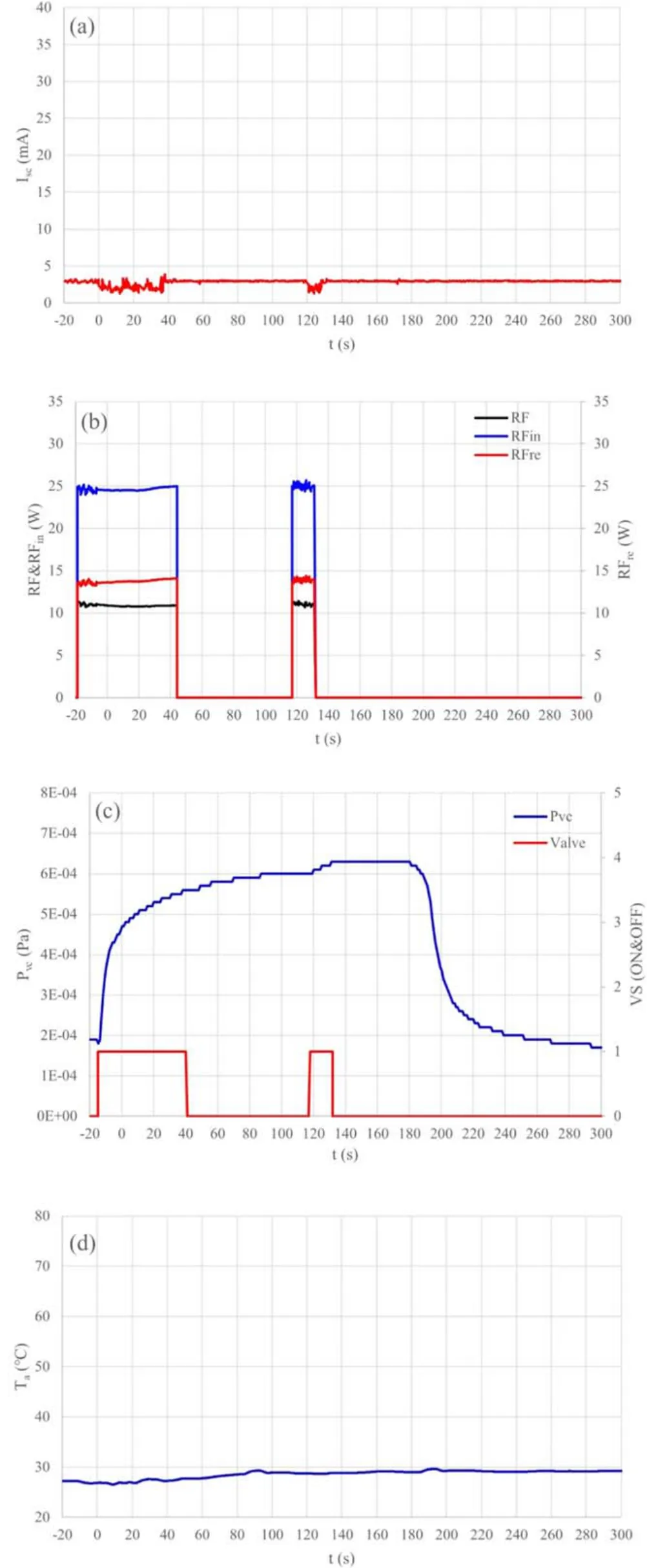
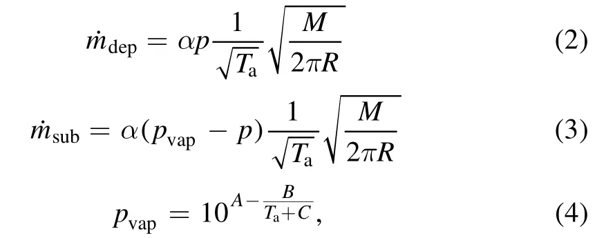
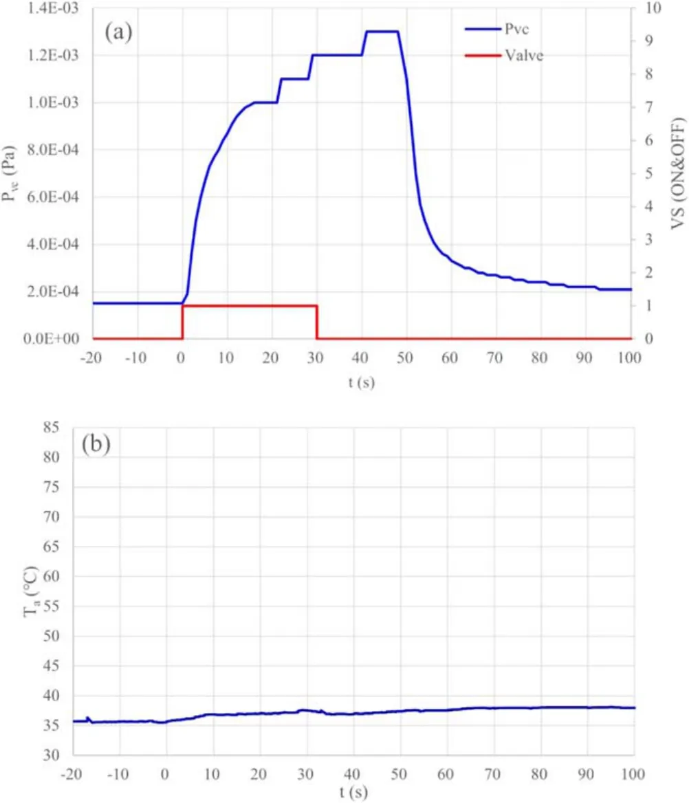
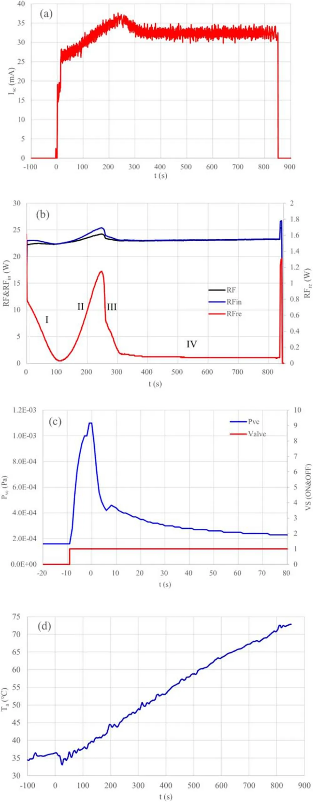
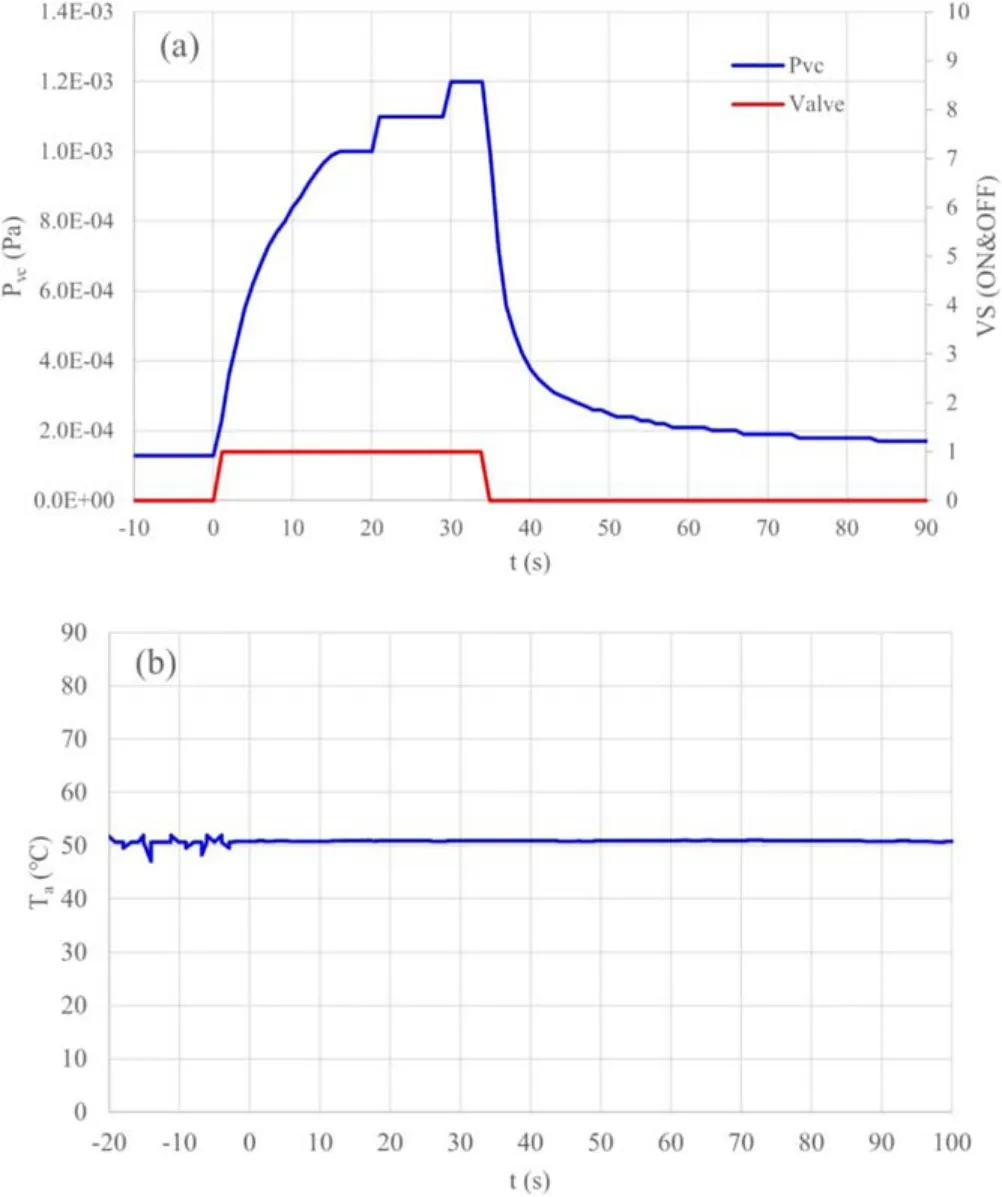
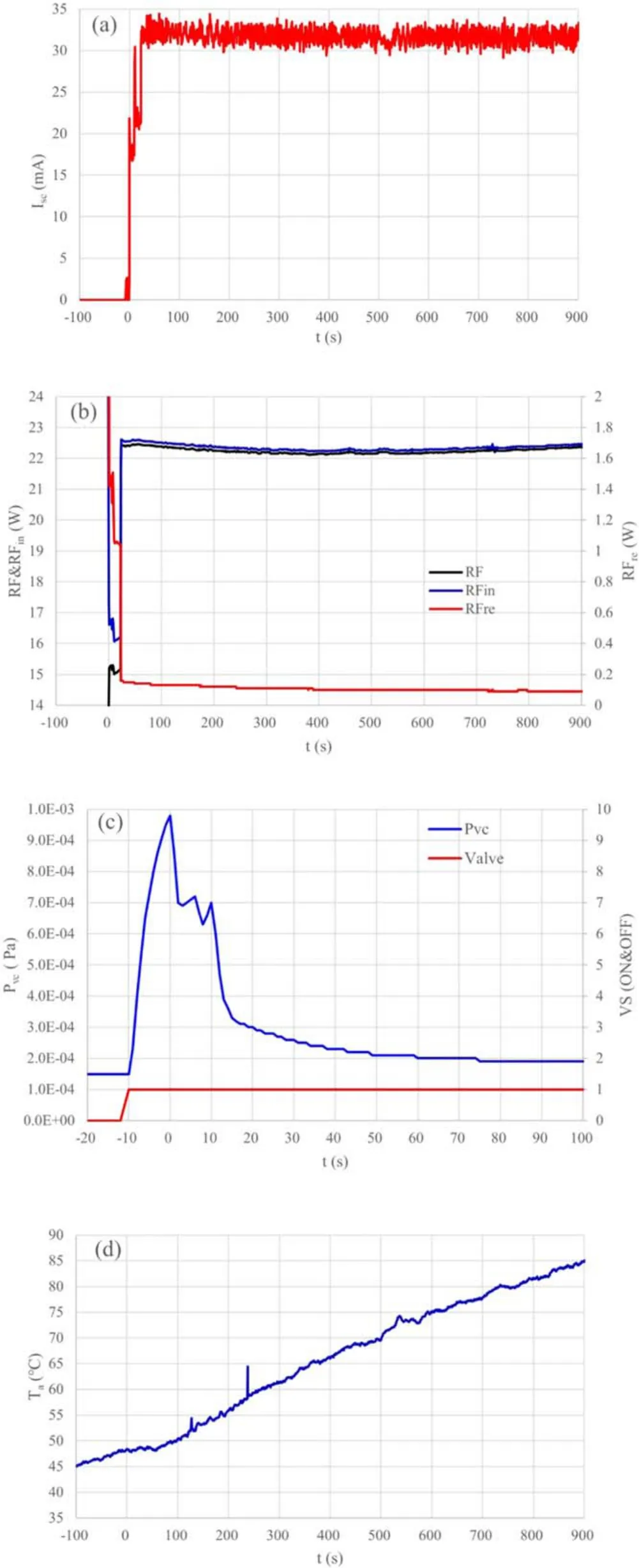
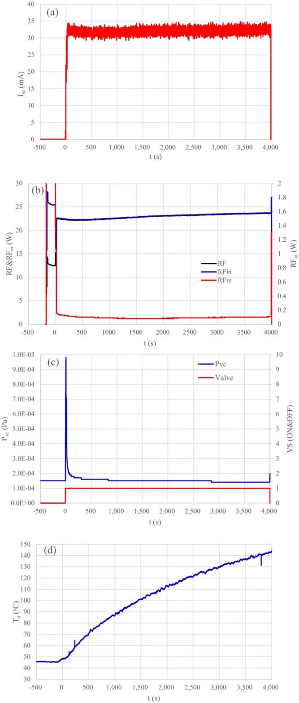
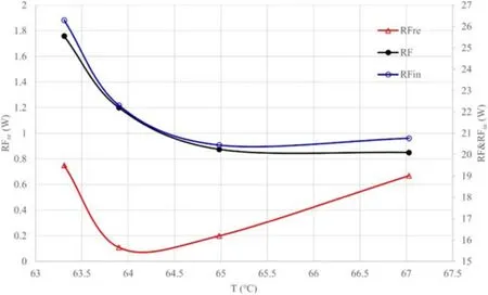
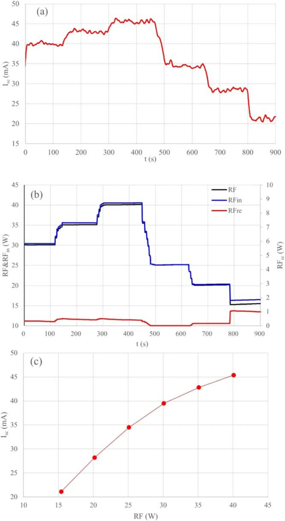
Abstract This paper reports the ignition performance of the iodine-fueled radio frequency (RF) ion thruster (IRIT) at different anode temperatures (Ta0).The experimental results show that the anode temperature plays important role on the ignition process of the IRIT.There were two characteristic temperatures related to the anode: the minimum ignition temperature (Ti0) and the stable ignition temperature (Tis), which were much lower than the pipeline temperature and the storage tank temperature.At Ta0 < Ti 0 ,it failed to discharge.When Ti0 ≤ Ta0 Keywords:radio frequency ion thruster,iodine propellant,ignition,deposition,sublimation,clog Nomenclature Iceelectron current emitted by the neutralizer/cathode Iscscreen grid current ˙maiodine flow rate into the discharge chamber ˙mdepiodine flow rate deposited in the anode ˙msubiodine flow rate sublimated from the anode ˙mtiodine flow rate out from the storage tank pvcpressure of the vacuum chamber RFnet input radio frequency power RFinincident radio frequency power RFrereflected radio frequency power Taanode/thruster temperature Ta0Taat ignition Ti0minimum ignition temperature Tisstable ignition temperature Ttanktemperature of the storage tank Tlinetemperature of the pipeline Uacacceleration grid voltage Uscscreen grid voltage VSvalve switching state The electric propulsion fueled by solid iodine propellant has become a research highlight in the past decades.Iodine is a feasible alternative to xenon to be used as a propellant for electric propulsion systems.There are obvious advantages using iodine instead of xenon:iodine is close to xenon in the propulsion performance, its density is 3 times of xenon(4.9 g cm?3@ room temperature versus 1.6 g cm?3@ room temperature and 2000 psi) and the price is 1/10, and the low pressure propellant feed system can be used, which is expected to make the propulsion system lighter, smaller and lower cost.Since the concept of iodine-fueled electric propulsion was put forward by Dressler et al [1] and Tverdokhlebov et al [2], it has been widely studied.Szabo et al[3–5], Kamhawi et al [6] and Smith et al [7] performed tests on the BHT series iodine Hall thrusters including BHT-200-I,BHT-600-I, BHT-1000 and BHT-8000.Liu et al [8] studied the ignition of the iodine cusped field thruster.Tsay et al[9, 10] studied the propulsion performance of the iodinefueled mini radio frequency (RF) ion thruster (IRIT) BIT3.Experiments were conducted on an iodine-fueled radio-frequency ion-thruster RIT-10 by Holste et al [11].Martínez et al [12] presented the development and testing of the NPT30-I2 ion gridded thruster.Yang et al [13] studied the performance of an iodine radio ion thruster IRIT4.The response of the magnetically enhanced plasma thruster has been studied by Manente et al [14, 15].In the above studies,the two propellants of xenon and iodine have shown comparable performances. One of the possible issues that can arise in an iodine propulsion system is that the vapor can redeposit to form a clog/blockage if a cold spot develops in the propellant lines,which makes the ignition characteristics of the iodine electric thruster at a lower temperature quite different from that of xenon.In general, to keep iodine from redepositing somewhere else within the system, the propellant lines should be kept significantly warmer than the solid iodine that is subliming to produce the iodine vapor[16].But for the thruster/anode, the situation is not exactly the same as the propellant lines of the propellant feed systems.On one hand, the anode acts as a cold sink on the lines, and that is a worst thermal case during the thruster ignition period as described by Samples et al [17].On the other hand, the thruster/anode is the propellant exit to vacuum and the low-pressure section,where it is relatively difficult to completely clog and it is possible for the thruster to ignite at a lower temperature.In the experiments of Paganucci et al [18], the HT100 Hall thruster was mounted on a plate with installed heaters to ensure that a temperature higher than 80 °C at the anode to avoid iodine condensation.But Sazbo et al [4] pointed out that the anode gas distributor does not have to be heated during ordinary thruster operation. To the best of our knowledge,no systematic study about the ignition characteristics of thrusters at different temperatures has been reported so far.This work will focus on the experimental study of the ignition characteristics of the IRIT4-2D IRIT [14] at different initial temperatures,especially at the temperatures lower than the propellant lines and the storage tank, and try to disclose the effect of iodine deposition-sublimation properties on the propulsion performance.The start-up temperature of iodine fueled thruster will be determined through the research, which is helpful to the thrust control strategy under different temperatures. The IRIT4-2D RF ion thruster (figure 1(a)) is a mission enabling, iodine-fueled ion propulsion system scheduled for launch in 2021, and it is a fully integrated propulsion system[19].The nominal operating point of the IRIT4-2D is at 150 W input power and 40 000 Ns total impulse, which produces 2 mN thrust and 2000 s specific impulse.The principle of the IRIT is shown in figure 1(b).Solid iodine propellant stored in the low pressure storage tank is heated to sublimate to a gaseous state, which is transferred into the thruster through the pipeline and then ionized to generate plasma by the coil-induced electromagnetic field, finally the ions are accelerated and extracted by the grid electrode to generate the thrust.Ions are neutralized by electrons emitted by neutralizers. The IRIT4-2D has a modular design, and include two sets of ion thrusters (anode), two sets of neutralizers (cathode), one iodine feed module as well as passive thermal management,and the power processing unit(PPU)integrated with the controller unit.The thruster has a diameter of 3.5 cm,which is an improved version of the 4 cm diameter thruster[13].By regulating the temperature of the storage tank,a flow rate range of 30–500 μg s?1can be achieved with the error less than±5%.The PPU module provides input power for the thruster, neutralizer and the iodine feed module, and realizes parameter monitoring and closed-loop control of thrust; the radio frequency is 2 MHz, and the DC voltage can reach 1800 V. The IRIT4-2D system used in the experiments in this work has passed the qualification level environmental test.Only one thruster, one neutralizer, a set of pipelines and one matcher were used in the experiment.For the laboratory purpose, the thruster, the RF power matcher, and the iodine feed module were placed in the vacuum chamber, while the PPU was located on the atmospheric side for ease of access to it (figure 2(a)).RIGOL DP832A and ITECH IT6942A DC power supply were used to supplied power the PPU with the input voltage of 28 ± 0.01 V.A computer with the special software was used for experiment control and data acquisition. Figure 1.The IRIT4-2D engineering prototype.(a) Photo of the prototype, (b) system block diagram. The experiment was carried out in a two-stage vacuum system, as described by Yang et al [13].The size of the square vacuum chamber in which the thruster is installed is 0.45 × 0.45 × 0.45 m3, and the size of the primary vacuum cylinder chamber is ?0.8 × 1.6 m (figure 2(a)).The vacuum chamber pressure (pvc) was measured with a ReBorn precision ionization gauge, model ZJ-12/CF35, with the measuring range from 1 × 10?1to 5 × 10?8Pa(1 × 10?3to 5 × 10?10mbar).This gauge was located at a flange on the side of the cylinder chamber approximately 1.2 m downstream from the thruster exit.The background neutral pressure could reach 5 × 10?5Pa (5 × 10?7mbar), andpvcis about 2 × 10?4Pa (2 × 10?6mbar) while the thruster is operational at the flow rate of 1 sccm xenon or the mass flow rate of 100 μg s?1iodine. In the experiment, only the anode/thruster temperature at ignition (Ta0) was changed, while the parameters such as the iodine flow rate out from the storage tank (˙mt), the incident radio frequency power (RFin), the screen grid voltage (Usc),the electron current emitted by cathode/neutralizer (Ice) and valve opening time remained unchanged.By monitoring the changes of screen grid current (Isc), the reflected radio frequency power (RFre),RFin,pvcand other parameters, the discharge performance of the thruster under differentTa0was analyzed, and the influence mechanism of iodine deposition and re-sublimation on thruster ignition was revealed.It was expected to obtain the minimum ignition temperature of the thruster (Tis) and the discharge over a wide range of temperature changes, which provides a basis for the design of thruster preheating method. The selection ofTa0was considered as follows.Obviously, ifTa0was the same as the temperature of the pipeline (Tline), the path in the thruster was unblocked and it could be ignited normally.Therefore,Tlinecould be used as the maximum temperature of the experiment.Meanwhile,IRIT4 could not ignite at room temperature(RT)according to our previous experiments, soRTcould be used as the lowest temperature of the experiment.Based on the above considerations,the range ofTa0in the experiment was set betweenRTandTline.Therefore,the experiments were divided into the following four cases. Figure 2.Experimental setup.(a) Schematic of the setup, (b) schematic of the thruster and the iodine feed module. Case 1.Ignition at low temperatures.Ta0was slightly higher thanRT. Case 2.Ignition at medium temperatures.Ta0was higher than the temperature in Case 1.Iodine deposit in the anode is not too serious and it could be ignited.However, the upper and lower limits of the temperature were unknown, and multiple attempts were made from lower temperature to higher one. Case 3.Ignition at high temperatures.Ta0was higher than the upper limit temperature in Case 2, and the flow path in the anode was completely unblocked.By analyzing thepvccurve at differentTa0, the lower limit of temperature in this case could be obtained.But in fact, it was found that this value could be predicted from the experimental results of Case 2. Case 4.Continuous firing at the high temperature.When the thruster is unblocked, ignites for a long time, and discharge performance was investigated during the process of the anode/thruster temperature (Ta) approaching the thermal equilibrium temperature of the thruster. Although multiple experiments were carried out, only one of the typical results was given in each case in this paper. For each of the above cases, a complete ignition test process includes the following 6 steps (figure 3). Step 1.Preheating the iodine feed module.Special heaters were used to heat the storage tank and the pipeline respectively.Closed loop control was adopted, and the temperature control accuracy reached ±0.1 °C.According to our previous flow test results [13], the temperature of the storage tank (Ttank) andTlinewere set to 63.8 °C and 85 °C respectively, with ˙mtof 100 μg s?1representing the nominal set point.Under this condition, the flow path inside the pipeline was completely unblocked. Figure 3.Steps of a typical ignition test. Step 2.Preheating the thruster (figure 2(b)).The anode was heated by RF power.The discharge chamber was directly heated by the RF coil,and tube A was heated by the discharge chamber.A PT1000 thermometer was installed on tube A to measure its temperature in real time.RFinwas set to about 23 W, andTarose slowly fromRT.RF power was turned off whenTaarrived at the target temperature ofTa0.WhenTawas slightly lower thanTa0,RF power was turned on manually again.Despite the measurement accuracy of PT1000 was as high as±0.1°C,the control error ofTa0was about±2°C due to the open-loop control. Step 3.pvctest.The valve was installed on the pipeline and close to the outlet of the storage tank (figure 2(b)).When the valve was opened, the iodine vapor in the storage tank flew into the anode through the pipeline, and then diffused from the anode outlet to the vacuum chamber.After the valve was closed, the iodine vapor flow was cut off and no longer flew into the pipeline and the anode.Whenpvcin the vacuum chamber decreased to about 2 × 10?4Pa (2 × 10?6mbar),the valve was opened and closed after about 30 s.At the rated flow of ˙ma= 100 μg s?1,pvcwas greater than 1 × 10?3Pa(1 × 10?5mbar).According to the relationship betweenpvcand ˙ma(see appendix A), it can be inferred that there was deposition in tube A of the anode or not.If tube A was clear,pvcrose rapidly at the moment of valve opening; moreover,pvcdecreased rapidly at the moment of valve closing.If thepvcrose slowly when the valve was opened,or it fell after the valve closing, it indicated that there was deposition or blockage in tube A.After closing the valve,the next step was proceeded until thepvcwas reduced to about 2 × 10?4Pa(2 × 10?6mbar) again. Step 4.Ignition.Whenpvcdropped to about 2 × 10?4Pa(2 × 10?6mbar) andTareachesTa0planned in step 2, the valve was opened again.Ignition was tried about 10 s later,whileRFinremained at 23 W,Ice,Uscand the acceleration grid voltage(Uac)were set to 30 mA,1400 ± 10 V and 200 ± 2 V respectively.A successful ignition or not was judged by the change ofIsc.An instantaneously increase ofIscindicated that a successful ignition and step 5 was carried out.Isc= 0 meant failure to ignition, and ignition was tried once more to eliminate the influence of random factors.After three unsuccessful ignition attempts within 5 s, step 6 would be carried out. Step 5.Continuous firing.Different from the closed-loop control mode of constant thrust on orbit, the thrust was not actively controlled during the discharge of the experiment in this work.Duration of the firing was set to be large than 600 s.When the thruster was operated under the rated parameters,Iscshould peak at about 32 mA instantaneously and remain constant, andRFreshould drop to below 0.2 W instantaneously.IfIscandRFrewere very different from the abovementioned values,Tahad a significant impact on the discharge process. Step 6.Shutting down and cooling down.The power supply of the screen grid, the accelerator grid, the RF generator, and the neutralizer were powered off in sequence, and the valve was closed finally.The thruster was cooled to room temperature, and the iodine feed module was kept warm or cool as needed. In each experiment, all the key parameters were measured in real time by the PPU with integrated controller and logged automatically through a special control software at a frequency of 1 Hz, includingIsc,Usc,Uac,RFin,RFre,Ice,Ta,Ttank,Tline, and the valve switching state (VS), etc.The net input radio frequency power of the thruster is denoted asRF,which is equal to the difference betweenRFinandRFre.VS= 0 means the valve is closed, andVS= 1 denotes it is opened.pvcmeasured by the ionization gauge was recorded by the vacuum chamber control software at a frequency of 1 Hz. Figure 4.Failure of ignition at Ta0 = 27.1 °C.(a) Is c ,(b) RFi n ,RFr e,RF, (c) pvc andVS, (d)Ta. Figure 4 shows the time histories ofIsc,RF,RFin,RFre,pvc,VSandTawhen the ignition try was atTa0= 27.1 °C.From 0 to 38 s, only small oscillations inIscwere observed (notice that there was an initial value of about 3 mA on theIsccurve),and the ignition failed.RF,RFinandRFrewere also almost unchanged.pvcindicated 1.8 × 10?4Pa before opening the valve.When the valve was opened,pvcincreased rapidly,reaching 5 × 10?4Pa (5 × 10?6mbar) after 22 s, and then increased slowly.In particular, when the valve was closed at 42 s,pvcdid not drop immediately, but continued to rise slowly.This indicates that iodine has deposited inside the thruster and a clog was produced.The iodine in the clog served as the second source of iodine sublimation.As it was elevated in temperature, although the iodine vapor flow from the storage tank was cut off after the valve was closed, the deposited iodine continued to volatilize and enter the vacuum chamber at a lower flow rate, which is similar to the phenomenon in the glass tube described by Polzin [16]. Tareached 28.9 °C at 117 s, and the valve was opened again at this time.pvcincreased only by 0.3 × 10?4Pa in 15 s,and the ignition failed again.After the valve was closed,pvcremained unchanged for 50 s.It was until 185 s thatpcbegan to drop rapidly, and it decreased to 3 × 10?4Pa(3 × 10?6mbar) in 20 s, which indicated that the clog was cleared and the flow rate reduced to zero. It can be seen that,the iodine vapor flowing from the tank through the pipeline will deposit inside the thruster and form a blockage whenTais too low.This causes ˙mato be much smaller thanm˙t,and it cannot be discharged under the rated ignition parameters ofRF,UscandIce,etc.This shows that there is a minimum ignition temperatureTi0for the iodine thruster.IfTa0is lower thanTi0due to the external environment of the satellite in orbit, the thruster cannot work, and it needs to be actively heated.The value ofTi0will be obtained in section 3.2. On the other hand,because the outlet of the thruster is in a high vacuum zone,the thruster has a certain degree of selfclearing ability; even at a lower temperature, all the iodine deposited inside the thruster will volatilize into the vacuum after a certain period of time. A simple model of the flow rate in the anode was established to analyze the above phenomena.˙macan be expressed by the following formula: where, ˙mdepis the iodine flow rate deposited in the anode,˙msubis the iodine flow rate sublimated from the anode.˙mtis a constant in this article, both ˙mdepand ˙msubare related to the thruster temperature,ambient air pressure,area,etc,which are given by equations (2)–(4) [17]. where,pvapis the vapour pressure of the solid iodine,pis the partial pressure of iodine in the gas phase,Tais the absolute temperatureTa,Ris the gas constant,αis a constant,Mis the molecular weight, A, B, and C are constants.It should be noted that although the same symbols ofpandαare used in equations (2) and (3), they may be different. It can be seen from equations (2) and (3) that ˙mdepincreases with the increasingp,while ˙msubdecreases.For the thruster,it is obvious thatpin tube A is much larger than that in the discharge chamber, which leads to easier to deposit in tube A than the latter.Therefore, equation (1) is mainly used to describe the situation in tube A. Figure 5.Pressure in the vacuum chamber at Ta of 35.8 °C.(a) pvc andVS, (b)Ta. From equations (2) and (3), the lowerTa,the largerm˙depand the smallerm˙sub.During the progress of ignition in Case 1,m˙dep>m˙sub,thusm˙a According to equation (3), sublimation will continue as long aspis less thanpvap.According to formula(4),thepvapof iodine at room temperature is about 94 Pa,while thepvcin the vacuum chamber is about 1 × 10?4–1 × 10?3Pa(1 × 10?6–1 × 10?5mbar) during the experiment.After the valve is closed, the deposited iodine will continue to volatilize, that is, the vacuum environment gives the thruster a certain dredging ability. Prior to the ignition test at a higher temperature, a dedicatedpvctest was done, and the results are presented in figure 5.Notice that valve opening time is taken as 0 time in the figure.The thruster was heated to 35.8°C and the valve was opened for 30 s.pvcrose to 1.0 × 10?3Pa(1.0 × 10?5mbar)in 14 s and reached 1.2 × 10?3Pa (1.2 × 10?5mbar) in 30 s.Its rising slope and maximum value are significantly higher than those ofTa= 27.1°C.After the valve was closed at 30 s,pvcdid not drop immediately, but still rose slowly.pvcpeaked at 1.3 × 10?3Pa (1.3 × 10?5mbar) at 47 s, and then dropped rapidly afterwards.It is shown that there was still iodine deposition in the thruster atTa= 35.8 °C, but the clogging was less than that ofTa= 27.1 °C. Figure 6.Discharge with clog-clearing at Ta0 = 38.2 °C: (a) Is c ,(b)RFi n, RFr e ,RF, (c) pvc andVS, (d)Ta. Figure 7.Pressure in the vacuum chamber at Ta0 = 50.9 °C.(a) pvc andVS, (b)Ta. Results ofTa= 38.2°C are shown in figure 6.The valve is opened 9 s before ignition.pvcrose quickly to 1.1 × 10?3Pa (1.1 × 10?5mbar), and dropped rapidly when it was discharged (appendix A), as illustrated in figure 6(c).Significant variation of rising-falling-stable was observed in figure 6(a) which plotsIscversus time t during discharge of 850 s.After successful discharge,Iscincreased to 27 mA almost instantly, and then linearly increased, peaking at 36 mA at 240 s.Since the test was not fully automated,manual adjustment was used to tuneRFinandUsc.Isc= 17 mA at the beginning corresponded toUsc= 800 V,and it arrived at 27 mA instantly after Uswas adjusted to 1400 V at 10 s.From 240 to 320 s,Iscdecreased from the maximum value of 36 to 33 mA.Iscstabilized to 33 mA after 320 s firing.Under the condition thatUscand other parameters remain unchanged,variation ofIscis mainly determined bym˙aandRFfor the radio frequency ion thruster.Iscincreases with the increasingm˙aorRF, on the contrary, a decrease inIscmeans a decrease of them. Oscillations also appeared on theRFin,RFreandRFcurve within 310 s after discharge, ranging from 22.3 to 24.2 W,with a maximum change of 1.9 W, and finally stabilized to 23.2 W.In particular dramatic oscillations occurred inRFrecurve, showing the decrease–increase–decrease–stable trend,as shown in figure 6(b).The discharge process can be divided into 4 stages according to the change ofRFre.Stage I:0–110 s,RFredecreased from 0.8 to 0.0 W; Stage II: 110–240 s,RFreincreased again to 1.2 W;Stage III:240–310 s,RFredecreased to 0.1 W; Stage IV: After 310 s,RFrestabilized to 0.1 W.Here, the change ofRFrewas mainly attributed to the change ofm˙a(appendix B).The above mentioned four stages are discussed in detail below combined with the relationship betweenm˙aandRFre. Phase I.At the moment of ignition 0 s, the iodine flow rate reached the discharge condition.Since a part of the iodine was redeposited in the thruster,m˙a Phase II.RFreincreased again (from 0 to 1.1 W), whileIsccontinued to increase by 6 mA (from 30 to 36 mA), andTaincreased from 40.6 °C to 47.8 °C.SinceUscand other parameters remained unchanged in the experiment, the increase ofIscwas mainly caused by the increase of ˙maand/orRF.From appendix C,an increase of 2 W(from 22 to 24 W)inRFcontributes about 2 mA toIscnearIsc= 30 mA.This confirms that the additional 4 mA of the increase inIscis caused by the increase inm˙a,that is, the increase inRFrein phase II corresponded to the increase inm˙a.The reason for the increasingm˙ais that asTafurther increased,m˙sincreased,and the clogged flow path gradually became clearing.At this time,m˙t-m˙dep+m˙sub>m˙t. Phase III.RFreandIscdecreased simultaneously withTaincreasing from 47.8°C to 52.8°C.This indicates that ˙mawas gradually decreasing because the iodine deposited in the thruster is gradually sublimating and exhausting, although it was still greater thanm˙t. Phase IV.Except thatTacontinued to increase (from 52.8°C to 76.9 °C),RFreandIsctended to stabilize.The iodine deposited inside the thruster has been fully utilized, and the flow remained steady atm˙a=m˙t. In short, it can be ignited whenTa0reachesTi0.But there are large oscillations atIscandRFre,which takes about a few minutes to stabilize.The thrust change is contributed to the change of ˙maduring the process of the iodine deposition and clearing inside the thruster.WhenTais low, the ˙mais lower than ˙mtdue to the deposition of iodine,resulting in a smallIscand a largeRFre.AsTarises,the deposited iodine serves as the second sublimation source, which may causem˙a=m˙t-m˙dep+m˙sub>m˙t,and bothIscandRFrewill reach larger values. Although figure 6 shows the result ofTa0= 38.2 °C, the value ofTi0of the thruster can be obtained by a detailed test.The specific operation method is as follows: heating the thruster to keepTarising continuously and slowly,try to ignite once when the temperature rises by 1°C,until the discharge is successful; The lowest value ofTaobtained upon successful discharge isTi0.Finally, theTi0of the IRIT4-2D is 36 °C,which is much lower thanTlineof 85 °C andTtankof 63.8 °C.For the condition ofTa≥Ti0, although the thrust fluctuates dramatically with manual open-loop controls,the stable thrust output can be easily obtained if feedback linking thrust to RF power is adopted, which is one of the advantages of the RF ion thruster. Also, it can be predicted that whenTa0is greater than a certain temperatureTis, there will be no clog, and a stable discharge curve can be obtained.WhenIscreaches the maximum value in Phase II,the thruster is completely unblocked,and the correspondingTavalue at this time isTis.It can be obtained from figure 6 thatIscpeaked at 36 mA at 240 s(figure 6(a)),andTawas 47.8°C(figure 6(d))at this time.So it can be inferred thatTis= 47.8 °C. Tawas set to be slightly higher than 47.8 °C according to theTisinferred from section 3.2.Similar to the previous section,a specialpvctest was done firstly to get the change ofpvcwhen the valve was opened and closed.Figure 7 shows thepvccurve ofTa= 50.9 °C.After the valve was opened,pvcrose rapidly, reaching 1.0 × 10?3Pa (1.0 × 10?5mbar) at 15 s and 1.2 × 10?3Pa(1.2 × 10?5mbar)at 34 s.The valve was closed at 34 s andpvcdrops immediately.It took only 5 s (from 34 to 39 s) forpvcto drop from 1.2 × 10?3Pa(1.2 × 10?5mbar)to 4.0 × 10?4Pa(4.0 × 10?6mbar).The ups and downs ofpvcwere completely synchronized with the opening and closing of the valve.This indicates that there was no iodine deposit or blockage inside the thruster, and the iodine flow path was completely cleared.This conforms with the prediction of the temperature required for no iodine deposits in the previous section. Figure 8 shows the result of discharge atTa0= 48.4 °C.The valve was opened 10 s before discharge.pvcrose rapidly when the valve was opened,and then fell rapidly immediately after the discharge-the trend was the same as that of Case 2.Tacontinued to rise from 48.4 °C to 84.9 °C within 900 s.Disregarding the two steps ofIscin the initial 22 s due to the manual adjustment ofUscandRF,IscandRFquickly stabilized to the maximum values of 32.0 mA and 22.3 W,respectively, whileRFrestabilized to the minimum value of 0.1 W. It can be seen that the discharge curve is stable whenTa0≥Tis, andTiscan be called the steady discharge temperature.For the thruster used in this work,Tisis 48.4°C,just as inferred in section 3.2.AlthoughTisis 12°C higher thanTi0,it is still much lower thanTlineof 85 °C andTtankof 63.7 °C.There are two reasons for this:first,the outlet of the thruster is directly facing the vacuum, which leads to the low back pressure and the large sublimation flow rate; second, the larger internal diameter and the shorter flow channel of the thruster than the pipelines result in the smaller flow resistance.It should be noted that the valueTisis related to the specific internal structure of the thruster, and it will be different for different thruster structures.Stable discharge can be achieved whenTais much lower thanTline, which is of great significance for reducing the preheating power consumption of the thruster and shortening its preheating time. Figure 8.Normal operation at Ta0 = 48.4 °C.(a) Is c ,(b) RFi n, RFr e,RF, (c) pvc andVS, (d)Ta. Figure 9.Continuous firing at Ta0 = 48.4 °C.(a) Is c ,(b) RFi n ,RFr e,RF, (c) pvc andVS, (d)Ta. For the experiment corresponding to figure 8 in Case 3, the thruster was kept firing continuously for 4000 s to test its long time scale stability with the large increases ofTa,and the result is shown in figure 9.AlthoughTaincreased from 48.4°C to 142.7 °C, the screen grid current and RF power remained stable, withIsc,RFandRFrebeing 32 mA, 23.5 W and 0.1 W,respectively.It can be seen that during the hourly continuous operation of the thruster,the thrust performance is hardly affected byTaeven if the temperature changes up to 94.3 °C.That is to say, whenTais high enough, the internal iodine path of the thruster is completely unblocked; the thermal throttling effect of the internal flow path of the thruster can be ignored so as not to reduce the flow rate, and the thrust can remain stable for a long time under the condition of a large temperature rise. In this paper, the experimental results of the IRIT4-2D IRIT ignited at different thruster/anode temperatures are presented.It is found that the inherent cold deposition characteristics of iodine make its ignition characteristics different from that of xenon.The main conclusions are as follows: (1) There is a lowest ignition temperatureTi0for the iodine thruster.AtTa (2) WhenTarises toTi0(36 °C), it can be ignited.ButIscandRFreoscillate dramatically in the first few minutes,which is mainly caused by the flow changes of the iodine vapor during the process of iodine deposition-toclearing in the thruster.At the beginning,m˙a (3) WhenTais higher thanTis(47.8 °C), the discharge process is stable.Tisis much lower thanTlineor even lower thanTtank,which can be attributed to the low back pressure and low flow resistance of the thruster facing the vacuum. (4) During the continuous operation of the thruster, the thrust performance is hardly affected by the temperature of the thruster even if the temperature changes up to about 100 °C. Notice that the values ofTi0andTismay vary for different internal structure of the thruster, but the ignition process will be similar.Research is helpful for reducing the preheating power consumption of the thruster, shortening the preheating time and designing the thrust control strategy. Acknowledgments The financial support from National Natural Science Foundation of China (No.11805265) and Key Laboratory of Micro-Satellites, Chinese Academy of Sciences (No.KFKT201903) is gratefully acknowledged. Figure B1.Variation of RF power with Ttank (˙ma) at Isc = 31.5 mA. Appendix A Relation betweenpvcand ˙maare briefly introduced in this section. Since the actual iodine flow rate exiting from the thruster is proportional topvcmeasured by the ionization gauge, the real-time ˙macan be obtained from thepvccurve. Rapidly decreasingpvcafter the successful ignition does not mean that the propellant flow rate is reduced, which is caused by the working principle of the ionization gauge ZJ12.The hot cathode in the ionization gauge emits electrons to ionize gas molecules, then the ions are collected by the collector, and the gas pressure is measured by the collected ion current.When the thruster is successfully discharged,most of the iodine is ionized and accelerated to the velocity of about 20 km s?1.Particles ofI+/I2/I/I2+/I2+etc impacts on the wall surface of the vacuum chamber,and a complicated sputtering reaction occurred.Only a small amount of iodine arrive at the site of the ionization gauge, resulting in that the measured pressure is very low.(The same phenomenon occurs on xenon in our experiments.) Appendix B Since a fixed frequency of 2 MHz and a fixed matching network were applied in the system,RFreis mostly affected by the change ofm˙a.This is illustrated by figure B1,which pl otsRF,RFinandRFreagainstTtank(˙ma)while keeping bothIscandUscconstant, wherem˙a=m˙tat high enoughTa.There is a downward-upward trend with the increasingTtank(˙ma), with the minimumRFreappears atTtank= 64.3 °C (˙ma= 110 μg s?1)which is close to the nominal flow rate of the system as designed. Appendix C A special test was arranged to get the contribution ofRFtoIsc,and the result is shown in figure C1.(Notice thatIscwas time-averaged in figure C1(a).) Keepingm˙a=m˙tat high enoughTa,theIsc?RFcurve was obtained by adjustingRFin.It can be seen that, nearIsc= 30 mA, an increase of 2 W(from 22 to 24 W) inRFcontributes about 2 mA toIsc. Figure C1.Isc changes with RF of non-blocking discharge.(a)Is c, (b)RF, (c) Isc?RF. ORCID iDs1.Introduction
2.Experimental procedure
2.1.System composition
2.2.Experimental methods
3.Results and discussion
3.1.Case 1: Ignition at low temperatures

3.2.Case 2: Ignition at medium temperatures
3.3.Case 3: Ignition at high temperatures
3.4.Case 4: Continuous firing at the high temperature
4.Conclusions
 Plasma Science and Technology2022年1期
