
Dynamic performance and control accuracy of a novel proportional valve with a switching technology-controlled pilot stage
2022-05-10 10:07:42QiZHONGEnguangXUTiweiJIAHuayongYANGBinZHANGYanbiaoLI
Qi ZHONG ,En-guang XU ,Ti-wei JIA ,Hua-yong YANG ,Bin ZHANG ,Yan-biao LI
1College of Mechanical Engineering,Zhejiang University of Technology,Hangzhou 310023,China
2State Key Laboratory of Fluid Power and Mechatronic Systems,Zhejiang University,Hangzhou 310027,China
3Key Laboratory of Special Purpose Equipment and Advanced Processing Technology,Ministry of Education and Zhejiang Province,Zhejiang University of Technology,Hangzhou 310023,China
Abstract:Two-stage directional valves usually employ proportional pilot control technology,which has the disadvantages of dead zones,leakage,and the large moving mass of the pilot valve.It is difficult,therefore,to achieve fast-response performance of the main valve.In order to overcome this problem,a switching pilot technology that employs two independent high-speed on/off valves(HSVs)is proposed to replace the traditional pilot proportional valve.Due to the rapid switching characteristics of HSVs,the dead zone of the pilot stage is avoided,and the dynamic response performance of the main valve is improved.The experiments indicate that the switching frequency of the pilot HSVs and supply pressure of the pilot stage have a very large effect on the dynamic performance and control accuracy of the main valve.Increasing the switching frequency of the pilot HSVs is helpful for improving main-valve control accuracy.The larger supply pressure of the pilot stage can achieve a faster dynamic performance of the main valve while causing larger static errors.The results show that the switching pilot technology can clearly improve the static and dynamic performances of the main valve.With the increase of pilot supply pressure,the step rise time is reduced from 21.4 ms to 16.8 ms,and the dynamic performance of the main valve is improved by 21.5%.With the increase of pilot switching frequency,the steady-state error decreases from 24 μm to 20 μm,and the control accuracy of the main valve is improved by 16.7%.
Key words:Pilot-operated proportional valve;Switching pilot stage;High-speed on/off valve (HSV);Dynamic performance;Control accuracy
1 Introduction
Proportional pilot valves have a strong flow capacity (Lantela et al.,2014;Yang and Pan,2015;Zhang et al.,2020) and are widely used in various hydraulic systems with a large flow characteristic,such as large-die forging presses,shields,and road machinery (Zhang et al.,2019).The performance of such large equipment is largely determined by the dynamic performance and control precision of hydraulic valves (Cheng et al.,2021;Zhong et al.,2021a;Ba et al.,2022).The pilot proportional valve is a typical two-stage hydraulic valve.The pilot stage controls the oil flowing into and out of the pressure chamber at both ends of the main valve,which is key to the dynamic performance of the main spool.
A proportional valve of small diameter is used as the pilot stage in the traditional proportional pilot hydraulic valve (Vukovic and Murrenhoff,2015),whose continuous fluid output drives and controls the main spool.However,due to the phenomenon of oil leakage in the pilot stage,the main spool moves and causes a steady-state error (Gao et al.,2022).Meanwhile,there is a dead zone in the pilot proportional valve,the spool motion mass,a friction coefficient between the spool body,and other problems,leading to the slow response of the pilot valve,and directly affecting the dynamic performance of the main spool.
Therefore,research has begun to study new technical solutions to avoid these problems.Switching techniques have been attempted for pilot-stage control.As the core hydraulic component of switching technology,the high-speed on/off valve(HSV)has the advantages of fast response speed,high switching frequency,compact structure,strong anti-pollution ability,simple processing,and low cost,but the flow rate of an HSV is small (Jien et al.,2008;Scheidl et al.,2012).The flow demand of the pilot stage is small,and so the HSV just meets only the requirements of the pilot stage.Since the HSV has only two working states,on and off (Brandstetter et al.,2017),it generates discrete fluid.By increasing the generation frequency of discrete fluid,it can match the transmission effect of continuous fluid (Paloniitty and Linjama,2017).Based on this idea,an HSV can be used in the pilot stage of a two-stage hydraulic valve to drive the main spool movement through the fusion of high-frequency discrete fluid.
Improving the dynamic and static performances of a two-stage hydraulic valve piloted by HSVs can be studied from the following three aspects:the structure of the pilot bridge,the driving algorithm of the single HSV,and the closed-loop control algorithm of the HSV pilot bridge.Using HSVs with different structures to create different forms of pilot bridge is helpful for improving the dynamic and static performances of the main valve.Winkler et al.(2010)and Huang et al.(2016) designed a novel poppet-valve structure,using an HSV as the pilot stage,and realizing the continuous,proportional control of the flow rate of the main valve by adjusting the duty ratio.Wang et al.(2017)used two HSVs to independently control each chamber of a three-way valve,so that the main stage could output continuous flow and pressure.In the study of Xiong and Huang (2018),a two-stage proportionalflow control valve was proposed,in which the pilot stage was composed of four,two-position,three-way HSVs in parallel to achieve a large flow through synchronous motion.
The dynamic performance of an HSV directly affects the control accuracy of the HSV control system,and so improving dynamic performance is helpful for improving the dynamic and static performances of the main valve (Zhong et al.,2021b).Optimizing different driving algorithms for an HSV is the key to improving the dynamic performance of the HSV.Top?u et al.(2006) proposed a current-control algorithm to reduce the opening and closing times of the HSV to 3 ms and 6 ms,respectively.In (Zhang et al.,2018),an adaptive pulse width modulation (PWM) algorithm for an HSV was adopted to effectively improve the total switching time of the HSV between 70.1% and 85.2%,and the dynamic performance range was controlled within the range of 6.8 ms to 7.1 ms.Zhou et al.(2016) applied an improved double-voltage driving algorithm to electromagnetic control,effectively shortening the closing time.Zhong et al.(2021c)proposed a multi-voltage compound driving strategy,which optimized the initial opening and closing current of the HSV through a pre-existing control algorithm(PECA),which greatly improved the response speed and reduced the opening and closing delay times by 66.7%and 87.5%,respectively.In(Zhong et al.,2021d),the energy conversion rate of the HSV was improved by 7.9%through PECA.
When the HSVs’ arrangement of the pilot stage and the dynamic characteristics of each HSV are fixed,optimizing the control algorithm of the pilot stage HSV’s group becomes the key to improving the movement performance of the main spool.In (Gao et al.,2019),a combination of an HSV and a directional valve was used to control the hydraulic cylinder,a particle swarm optimization algorithm was used to identify the parameters,and an adaptive robust controller was designed to achieve high-precision position tracking of the hydraulic cylinder.Liu (2010) effectively controlled the direction and flow of the main valve by changing the PWM of the control signals of different HSVs in the pilot stage,thus improving control accuracy.Tang (2006) established a poppet valve-cylinder system with an HSV as the pilot valve and adopted a fuzzy proportional-integral-derivative (PID) control algorithm to effectively control the position of the main spool.Xiong and Huang (2018) adopted the PWM control strategy for the valve control system and optimized the dynamic characteristics of the main valve through peak and hold technology.In (Gao,2022),a pressure controller consisting of a differential PWM scheme,asymmetric pressure difference compensation,and nonlinear adaptive control is proposed to ensure good pressure tracking performance and enhance system robustness.
Combined with the above research,a digital hydraulic pilot valve (DHPV) is proposed in this paper,in which the pilot stage is composed of two,two-position,three-way HSVs and controls the two pressure chambers of the main spool.At the same time,the adaptive supply pressure driving algorithm(ASPDA) is adopted to optimize the HSV dynamic characteristics (Zhang et al.,2018) to improve the dynamic performance of the pilot HSV while maintaining its stability,so that it is not affected by changes in system load and oil supply pressure (Zhong et al.,2021e).On the basis of these,a segment-based PID control algorithm for the main spool displacement controller is proposed in this paper.By increasing the oil supply pressure of the pilot HSV and the switching frequency,the dynamic performance and control accuracy of the main valve are optimized.The response time of the main valve is shortened by 4.6 ms and the dynamic performance is improved by 21.5%.The steady-state error is controlled within 20 μm.
In this paper,the DHPV model is introduced first,and the working principle and mathematical model of the pilot valve and the main valve are presented.Next,the control algorithm of the pilot valve and main valve is introduced.Then,experimental analysis is shown,and the main conclusions are summarized.
2 Modeling of the DHPV
The DHPV proposed in this study is a symmetrical,two-stage hydraulic spool structure,which can take on the function of an independent control of the load port,as shown in Fig.1.Theoretically,the two main spools and their corresponding pilot stages have the same structural parameters.Therefore,the mathematical modeling analysis of the two-stage hydraulic valve is only carried out with the main spool and its pilot stage in Fig.1a.For the purpose of this study,the four HSVs shown in Fig.1b are named HSV1,HSV2,HSV3,and HSV4 from left to right.
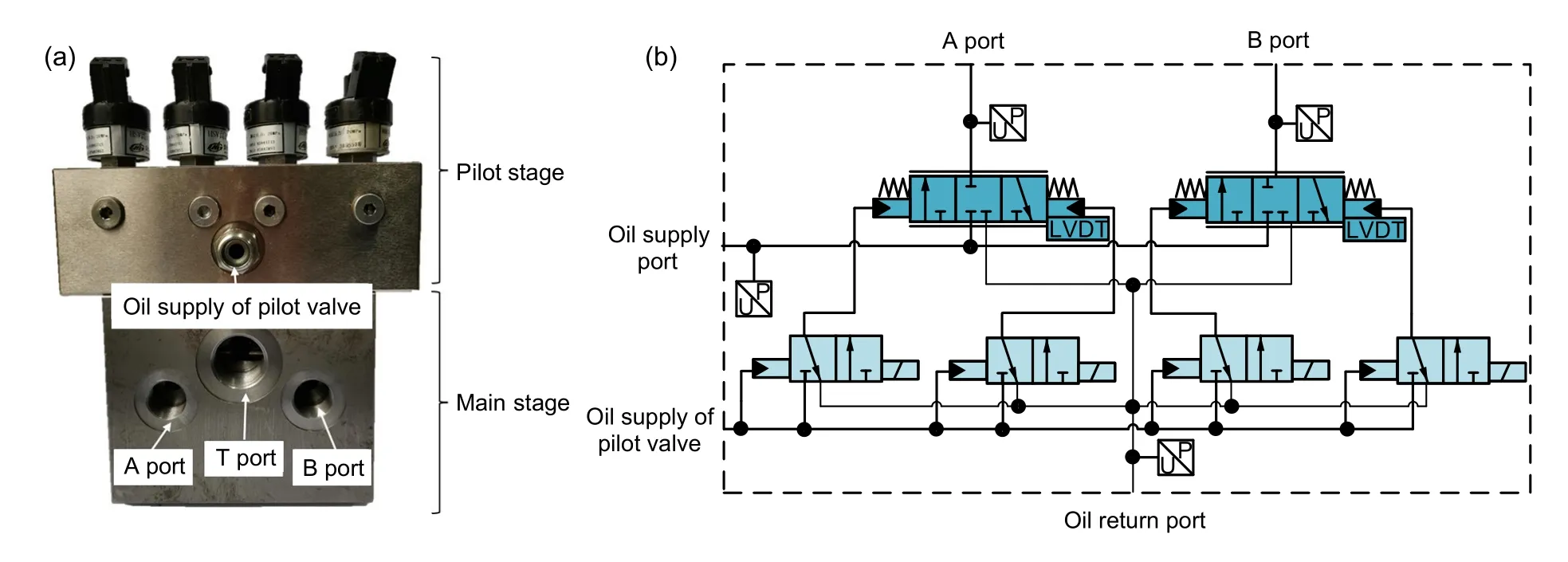
Fig.1 Photo of the DHPV(a)and the schematic diagram of the DHPV(b)
2.1 Modeling of the pilot stage
The HSV structure of the two-position,threeway ball valve is shown in Fig.2.Port P is the oil inlet,port A is the working port,and port T is the oil return port.When the coil is energized,the electromagnetic force overcomes the resistance such as the hydraulic pressure,and the armature drives the two steel balls and the separation pin to the right.At this time,port P is connected to port A,port T is disconnected from port A,and the HSV is open,as shown in Fig.2a.When the coil is powered off,the hydraulic pressure acting on the right steel ball overcomes the remaining electromagnetic force and resistance and pushes the two steel balls and the separation pin to the left.Then port P is disconnected from port A,port T is connected to port A,and the HSV is closed,as shown in Fig.2b.
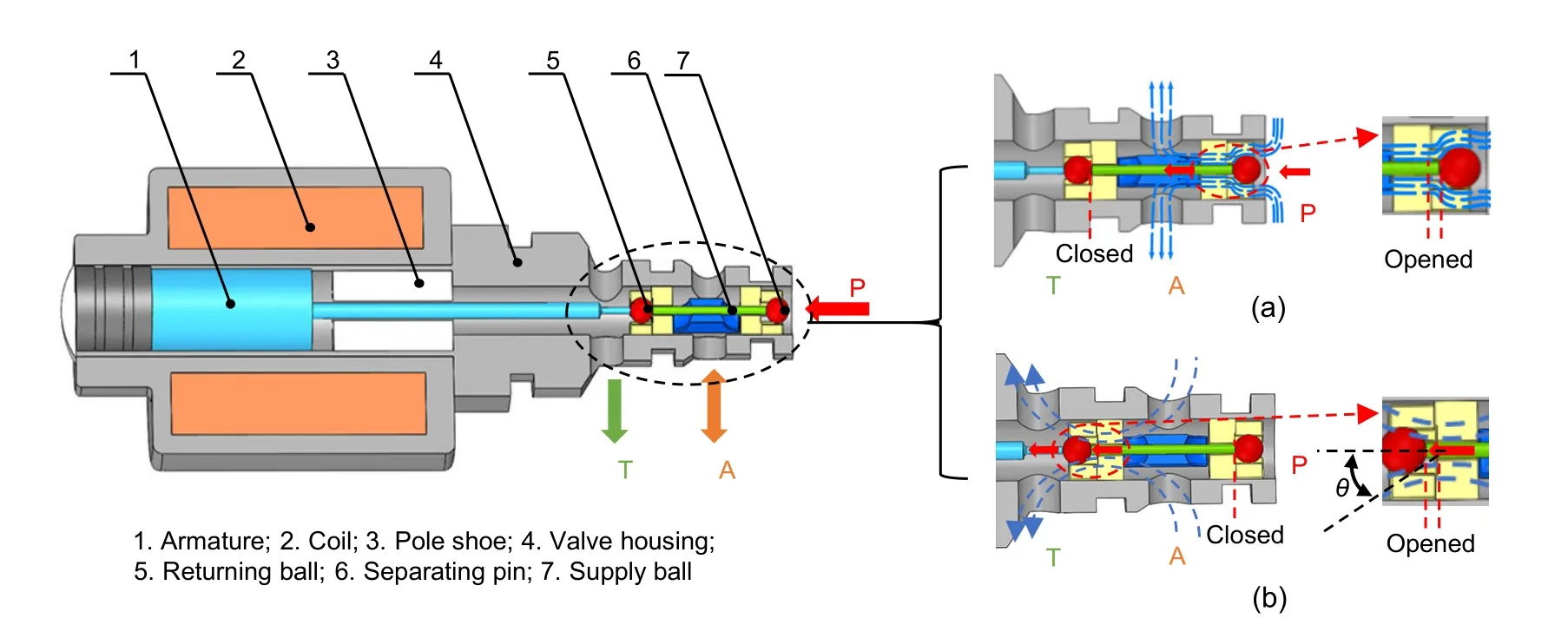
Fig.2 Structure of the tested HSV(θ is the flow angle)
The HSV converts electrical energy into mechanical energy through an electric-mechanical converter and ultimately pushes the spool to control the oil.The energy transfer process can be seen in Fig.3.
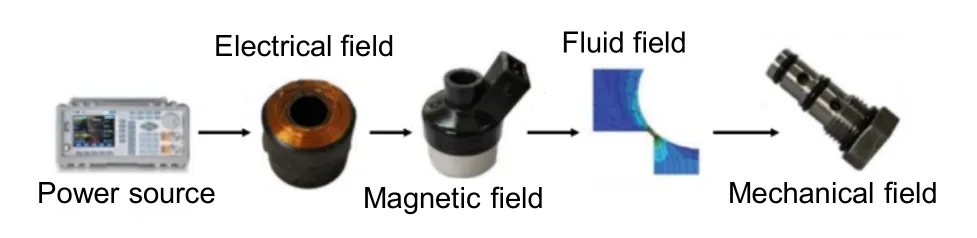
Fig.3 Energy conversion of the HSV
2.1.1 Electrical field
The electrical field of the HSV in its working state can be expressed as:
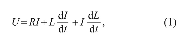
whereUdenotes the driving voltage,Ris the equivalent resistance,Iis the current in the coil,tis the time,andLis the equivalent inductance.
2.1.2 Magnetic field
Because the solenoid assembly air gap of the HSV is smaller than the working air gap,the assembly air gap can be ignored.The magnetic field of the electro-mechanical converter can be expressed as:
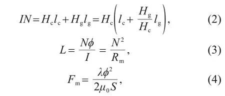
whereNdenotes the number of coil turns;HcandHgare the equivalent magnetic field strengths of magnetic materials and air gaps,respectively;lcandlgare the equivalent lengths of the magnetic circuit in the magnetic material and air gap,respectively;φis the air-gap flux;Rmdenotes the equivalent reluctance of the total magnetic circuit;Fmshows the electromagnetic force;λis the leakage coefficient;μ0is the air permeability;Sdenotes the cross-section area of the air gap.
2.1.3 Fluid field
According to the flow equation,the flow through the HSV can be expressed as:
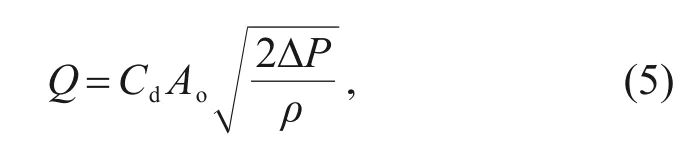
whereQis the flow rate of the HSV,Cdis the discharge coefficient,Aodenotes the open area of the orifice,ΔPdenotes the pressure drop through the orifice,andρis the density of the oil.
The flow force is caused by the changes of hydrodynamic momentum.Therefore,the steady-state flow force and transient flow force acting on the spool can be expressed as:
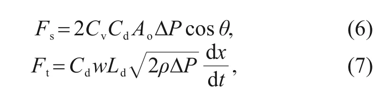
whereFsandFtdenote the steady-state flow force and transient flow force acting on the spool,respectively,Cvdenotes the fluid velocity coefficient,θis the flow angle,wis the area gradient,Lddenotes the damping length,andxdenotes the displacement of the armature.
2.1.4 Mechanical field
The dynamic equation of the HSV can be expressed as:
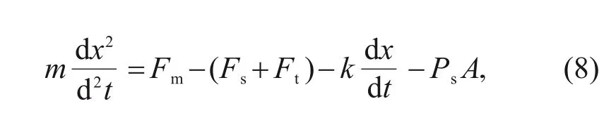
wheremis the mass of the moving parts,kis the coefficient of viscous friction force,Psdenotes the supply pressure,andArepresents the effective cross-section area of port P.
2.1.5 Analysis of dynamic characteristic
When HSV is in the critical opening and closing states,its moving parts are still in the static state,and so the acceleration and velocity are both zero.The critical electromagnetic force can be expressed as:
whereFcmdenotes the critical electromagnetic force required to drive the opening and closing of the HSV.
The direction of the steady-state flow force is pointing in the closing of the valve port.Therefore,the critical electromagnetic force required when the HSV switches from the closing state to the opening state is:
wherePATis the pressure difference between port A and port T.Similarly,when the HSV switches from the opening state to the closing state,the critical electromagnetic force required is:
wherePPAdenotes the pressure difference between port P and port A.
According to Eqs.(2)-(4),(10),and (11),the critical current required to generate the critical electromagnetic force can be obtained as:
whereIonis the critical opening current,andIoffis the critical closing current.LonandLoffdenote the equivalent inductance of the HSV in the on and off states,respectively.
When the HSV is on or off,its equivalent inductance is constant,and so the current in the coil can be expressed as:
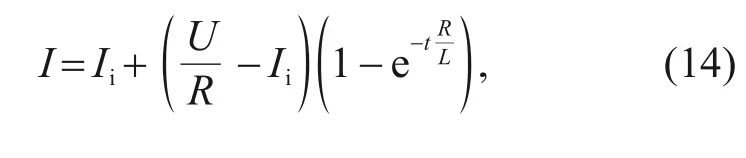
whereIiis the initial current in the coil.According to the transformation of Eq.(14),the delay time of the current change can be obtained:
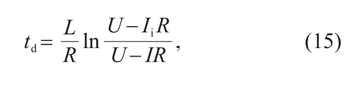
wheretddenotes the delay time.Therefore,the delay time of the HSV opening and closing can be expressed as:
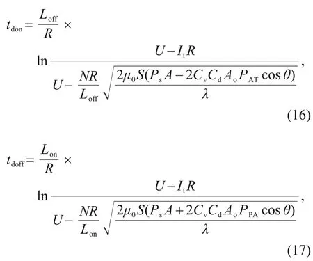
wheretdonandtdoffdenote the delay times of the opening and closing of the HSV,respectively.
According to Eqs.(12) and (13),it can be concluded that the different oil supply pressures will change the critical opening and closing currents of the HSV.
According to Eqs.(8),(16),and (17),it is easy to find that the oil supply pressure has a strong influence on the dynamic characteristics of the HSV.With an increase of oil supply pressure,the opening delay time of the HSV increases,while the closing delay time decreases.
2.2 Modeling of the main stage
The pilot HSV works in a fast opening and closing state,and the output flow is small.The highfrequency discrete fluid generated by the pilot HSV can be approximately viewed as a continuous fluid after the damping effect of the pressure chamber and the connecting oil circuit.The average flow of the HSV can be expressed as:
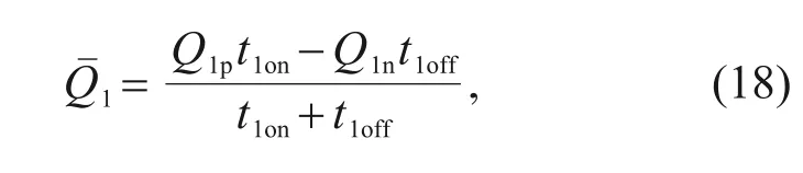
whereis the average flow rate of HSV1;t1onandt1offrepresent the times when HSV1 is on and off in a single working cycle,respectively;Q1pandQ1nrepresent the flow rates in the opening and closing states of HSV1,respectively.
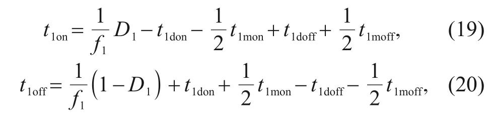
wheref1is the frequency of the HSV1 control signal;D1denotes the duty ratio of the HSV1 control signal;t1don,t1mon,t1doff,andt1moffdenote the opening delay time,opening motion time,closing delay time,and closing motion time of HSV1,respectively,as shown in Fig.4.
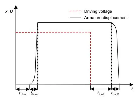
Fig.4 Dynamic behavior of the HSV
It can be seen from the above that,with the increase of the duty ratio of the control signals,the flow into the pressure-control chamber of the main spool gradually increases,while the flow out of the pressure-control chamber gradually decreases.When≥0,this means that the flow into the pressurecontrol chamber of the main spool through HSV1 is greater than the flow out of the pressure-control chamber of the main spool,resulting in the main spool moving to the right in Fig.5.Conversely,when<0,the main spool moves to the left.

Fig.5 Structure diagram of the DHPV.Qm is the output flow rate of the main valve;is the average flow rate of HSV2
According to Newton’s second law,the motion equation of the main spool can be expressed as:
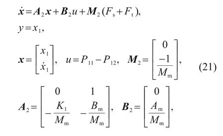
whereMmis the mass of the main moving parts,x1is the moving displacement of the spool,P11andP12represent the pressures on the left and right sides of the main spool control chamber,respectively,Amis the effective cross-sectional area of the spool,K1is the spring elastic coefficient of the spool,andBmis the damping coefficient of the spool when it moves.
According to the flow continuity equation,the pressure in the control chamber of the main valve can be expressed as:
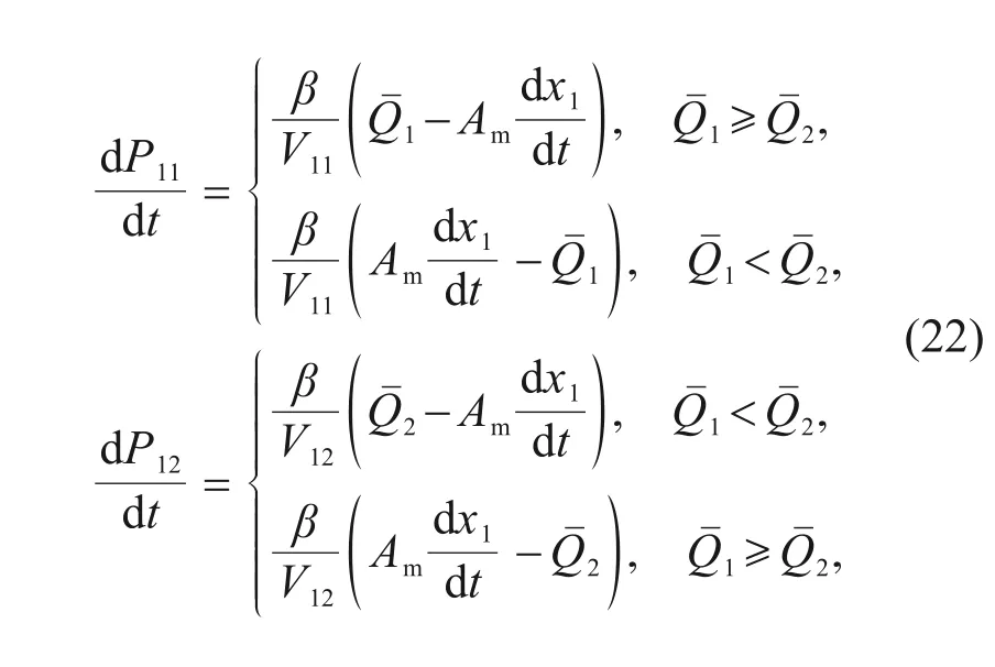
whereβis the bulk modulus of elasticity,andV11andV12represent the volumes of the left and right chambers of the main spool,respectively.
It can be seen from the above that the HSV flow rate is the key to the dynamic performance of the main spool,and the oil supply pressure of the pilot stage has a direct impact on the HSV flow rate.The higher the oil supply pressure achieved in the pilot stage,the better are the dynamic characteristics of the main spool.
3 Development of the advanced digital controller
3.1 HSV controller
The dynamic performance of the main valve is directly affected by the dynamic performance of the pilot HSV.The better dynamic performance of the pilot HSV can lead to better dynamic performance of the main valve.The hardware framework of ASPDA adopted in this study is shown in Fig.6,which includes the controller,voltage source,current detector,pressure detector,and tested HSV.
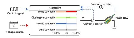
Fig.6 Hardware implements of ASPDA
In this method,the first cycle of the HSV is divided into four stages,as shown in Fig.7.They are the opening stage,the pre-closing stage,the closing stage,and the maintaining closed stage.The second cycle continues to repeat the above stages.
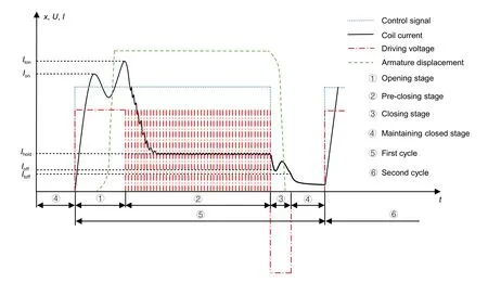
Fig.7 Dynamic behavior of the HSV under ASPDA.Iton is the trigger opening current;Itoff is the trigger closing current;Ihold is the holding current
When the system starts,the pressure detector detects the pressure of the HSV oil supply chamber and feeds it back to the controller.According to the current oil supply pressure,the controller updates the corresponding critical opening and closing currents(Ion,Ioff)and the value of the adjustable voltage source.
To ensure that at the moment when the high voltage switches to the adjustable voltage the HSV has been fully turned on,the trigger opening currentItonshould be slightly larger than the actual critical opening currentIon.By contrast,to ensure that at the moment when the negative voltage switches to zero voltage the HSV has been completely turned off,the trigger closing currentItoffshould be slightly less than the actual critical closing currentIoff.In addition,the value of the adjustable voltage source should be slightly greater than the product of the equivalent resistance and the critical closing current to maintain the opening stage of the HSV,by making the coil current closer to the critical closing current and reducing the closing delay time.
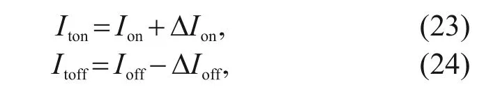
where ΔIonis the difference between the trigger opening current and the critical opening current,and ΔIoffis the difference between the trigger closing current and the critical closing current.
According to Eq.(13),the adjustable voltage used in the pre-closing stage can be deduced as:
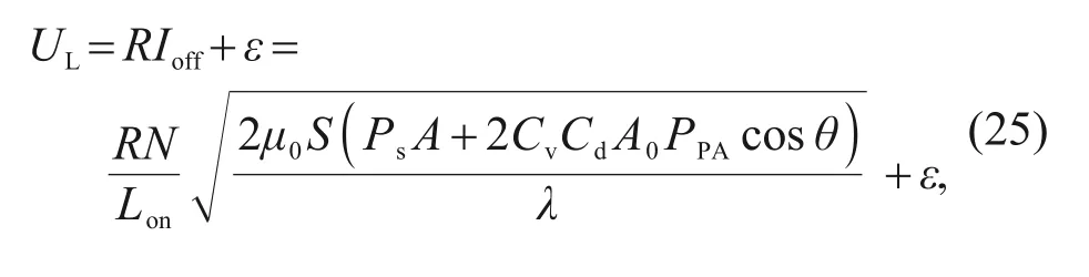
whereULis the product of the driving voltage and the low duty ratio value,andεis the voltage compensation value.
When the rising edge of the control signal arrives,the controller outputs a voltage signal with a 100%duty ratio for the opening stage to rapidly increase the current.When the current reaches the trigger valueIton,the controller switches to the adjustable voltage source to drive the HSV.When the falling edge of the control signal comes,the controller drives the HSV with a-100% duty ratio for the closing stage to create the unloading function until it reaches the trigger valueItoff.At this point,the HSV is turned off and the controller switches to the zero-voltage source to keep the HSV off.
3.2 Main spool controller
Due to the phenomenon of the opening and closing delays of the pilot HSV,the HSV has certain dead zone characteristics when the duty ratio of the control signal is small,and certain saturation characteristics when the duty ratio is large.Therefore,there is an inevitable deviation between the actual duty ratio of the HSV and the duty ratio of the control signal,and this deviation is affected by the oil supply pressure.The ratio between the average output flow rate of the HSV and its maximum flow rate is taken as the standard to measure the flow characteristics of the HSV.The flow characteristics,when driven by a 50-Hz control signal,are shown in Fig.8,and the specific parameters are shown in Table 1.
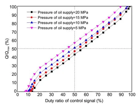
Fig.8 Flow characteristics of the HSV with the drive frequency of 50 Hz.Qmax is the maximum flow rate
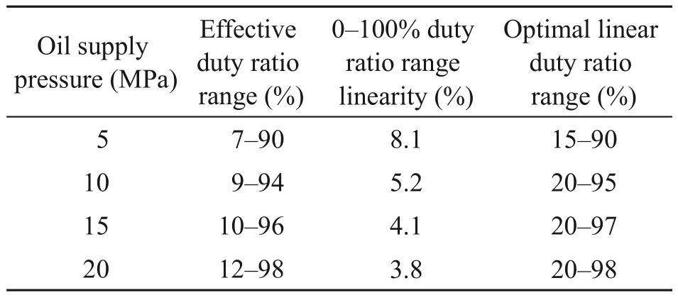
Table 1 Flow characteristic parameters of the HSV(drive frequency is 50 Hz)
With the increase of oil supply pressure,the opening delay time of the pilot HSV increases,while the closing delay time decreases,resulting in minimum and maximum controllable duty ratios that increase with the oil supply pressure.However,the effective duty ratio range of the control signal is always maintained above 83%,and the optimal linear duty ratio range is maintained above 75%,which is not affected by the change of the oil supply pressure.Moreover,the flow gain of each curve is consistent within the range of the optimal linear duty ratio.The above characteristics ensure a stable proportional relationship between the average output flow of the HSV and the duty ratio of its control signal.They also ensure a good control effect when the HSV pilot controls the movement of the main spool.
As the dynamic opening and closing times of the HSV are determined under constant working conditions,the ratio of the dynamic opening and closing times to the whole working cycle changes with the change of the frequency of the control signal.Thus,the frequency of the HSV control signal has a great influence on its flow characteristics.Similarly,taking no-load as an example,when the oil supply pressure is 10 MPa,the relationship between the HSV flow characteristics and its control signal frequency is as shown in Fig.9,and the specific parameters are shown in Table 2.
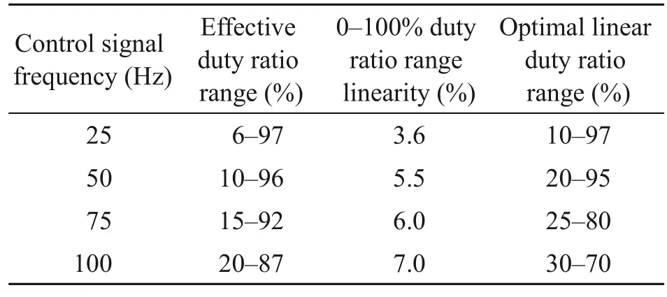
Table 2 Flow characteristic parameters of the HSV (oil supply pressure is 10 MPa)
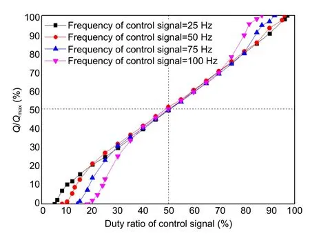
Fig.9 Flow characteristics of the HSV with the oil supply pressure of 10 MPa
According to the curves in Fig.9,the lower frequency of the HSV control signal can achieve a better linearity of its flow characteristic curve while causing the larger range of effective duty ratio and optimallinear duty ratio of the control signal.Although the range of the optimal linear duty ratio is affected by the frequency of the control signal,the flow gain within the range of the optimal linear duty ratio is always consistent,and the curves coincide with each other in height.This feature ensures that the main spool still has the same sensitivity when the pilot HSV is operated at a variable frequency.
In this study,a segment-based PID control algorithm is proposed for the main spool displacement controller.According to the flow curves in Figs.8 and 9,a 50%duty ratio is in the center of the linear range of the pilot HSV flow rate.Therefore,when the linear range near the 50% duty ratio is controlled,the average output flow rate of the HSV will have better proportional characteristics.Combined with the above reasons,the initial control duty ratio of each HSV is set to 50%.The duty ratios of HSV1 and HSV2 can be expressed as:
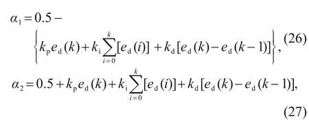
whereα1andα2represent the duty ratios of HSV1 and HSV2,respectively,ed(k) is the displacement error of the main spool,kis the positive integer,andkp,ki,andkdare the control parameters of the PID algorithm,whose value rules are shown in Table 3.
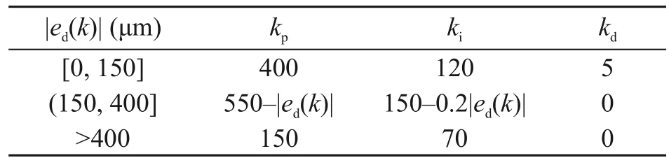
Table 3 Rules of the displacement controller
Under the condition of a certain pressure difference,the control error is large at the initial stage of the step motion.As shown in Fig.10,from 27 ms to 33 ms,the duty ratios of HSV1 and HSV2 are in the dead-zone range (normally closed stage) and saturation range (normally opening stage),respectively,and so the displacement of the main spool increases linearly.From 46 ms to 50 ms,the control signal duty ratios of HSV1 and HSV2 are normally closed,and the main spool does not move.From 75 ms to 78 ms,the duty ratios of HSV1 and HSV2 control signals are in the normally opening state,and the main spool does not move.Thus,as long as the duty ratios of the HSV1 and HSV2 control signals are not equal,one HSV will open and the other will close,and the main spool will move.
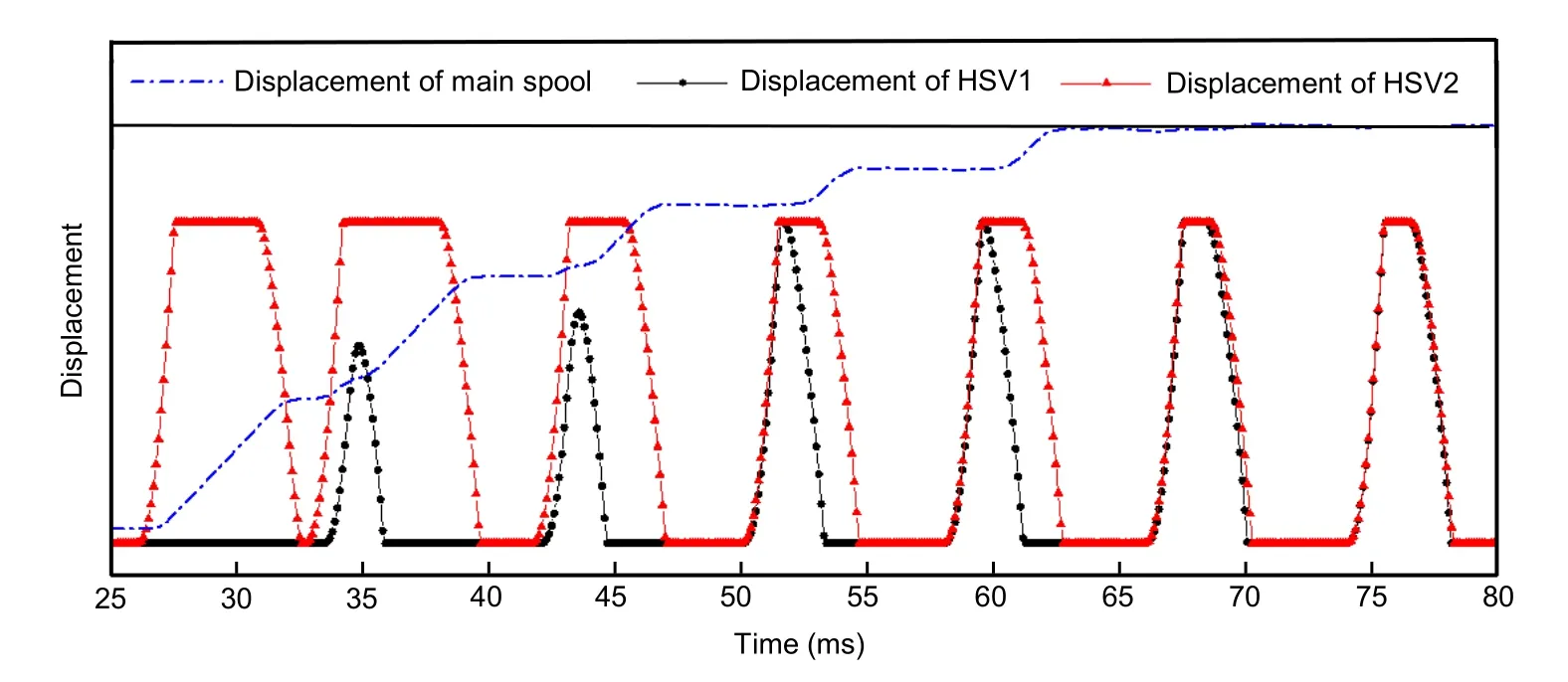
Fig.10 Relationship between main spool displacement characteristics and pilot valve state
4 Experiment analysis
In this study,the dynamic and static performances of DHPV are experimentally studied.The experimental environment is shown in Fig.11,in which the NI 9505 servo drive board built-in current-detection module can detect the state of the current in the loop.At the same time,the NI 9205 data-acquisition board is used to collect the control voltage signal and the pressure detector signal.

Fig.11 Photo of the experimental system.FPGA is the field programmable gate array
The dynamic and static performances of the DHPV,when the supply pressure of the pilot stage is 10 MPa and the drive frequency is 50 Hz,are shown in Fig.12.The rise time required for the main spool to move in a 1-mm step is 24.2 ms,and there is no obvious overshoot during the dynamic process.Due to the action of discrete fluid,when the main spool is stable around 1 mm,there appears in the spool a small delay and the maximum displacement fluctuation distance is close to 24 μm.When the main spool moves in a 2-mm step,its rise time is 24.4 ms,and a displacement overshoot of 22 μm appears.After the main spool is stabilized,the steady-state error is kept within 25 μm.When the main spool moves in a 3-mm step,the rise time is about 33.0 ms,the displacement overshoot is close to 33 μm,and the steady-state error is controlled within 28 μm.
Fig.12 Dynamic and static performance of the DHPV(drive frequency is 50 Hz):(a)displacement dynamic characteristics;(b)displacement steady-state characteristics
On increasing the drive frequency to 75 Hz and repeating the experiment,as shown in Fig.13,the rise times of the main spool are 20.8 ms,21.0 ms,and 20.5 ms for 1-mm,2-mm,and 3-mm step movements,respectively.The overshoots of each step movement are 12 μm,38 μm,and 23 μm,respectively.The steadystate errors are 21 μm,22 μm,and 25 μm,respectively.
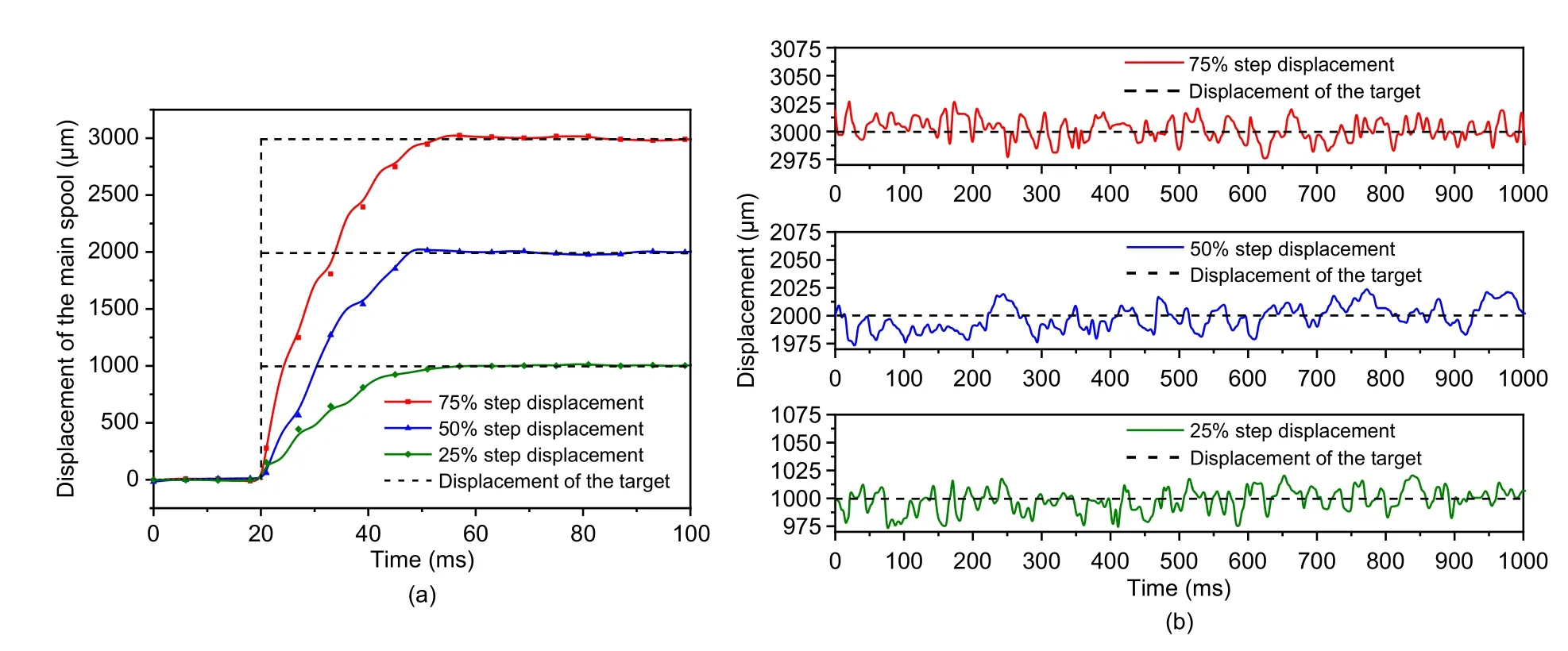
Fig.13 Dynamic and static performance of the DHPV(drive frequency is 75 Hz):(a)displacement dynamic characteristics;(b)displacement steady-state characteristics
When the drive frequency is further increased to 100 Hz,as shown in Fig.14,the rise times of the main spool are 15.3 ms,21.4 ms,and 22.8 ms for 1-mm,2-mm,and 3-mm step movements,and the overshoots of each step movement are 15 μm,34 μm,and 27 μm,respectively.The steady-state errors are 20 μm,22 μm,and 24 μm,respectively.
Fig.14 Dynamic and static performance of the DHPV(drive frequency is 100 Hz):(a)displacement dynamic characteristics;(b)displacement steady-state characteristics
In this study,the overshoots,rise times,and steady-state errors of the main valve during the step movements of 25% (1-mm),50% (2-mm),and 75%(3-mm) are selected as evaluation indices (Zhong et al.,2019),and the specific parameters are shown in Table 4.
According to the above experimental analysis,the closed-loop control cycle of the main spool is the opening and closing cycle of the pilot HSV.The main spool displacement is adjusted by changing the duty ratio of the HSV in each working cycle.If the HSV switching frequency is higher,the frequency of the main spool displacement closed-loop control will be higher,and then the number of opening and closing cycles of the pilot valve per unit of time will be greater,the number of times to adjust the HSV control signal will be greater,and the control accuracy will be higher.As shown in Table 4,with the increase of driving frequency,the control accuracy of the step movement from 1 mm to 3 mm of the main valve increases by 16.7%,12.0%,and 14.3%,respectively.Therefore,the driving frequency of the HSV directly affects the static performance of the main valve and increasing the pilot switching frequency is helpful for improving the control accuracy of the main valve.
Because the supply pressure of the pilot stage has a direct impact on HSV flow,HSV flow is the key to determining the movement of the main spool.Therefore,the influence of the supply pressure of the pilot stage on the motion characteristics of the main spool is analyzed in this study,and the results are shown in Fig.15 and Table 5.Taking the driving frequency as 100 Hz and the main spool as performing a 2-mm displacement step as an example,with the increase of supply pressure,the rise time decreases from 21.4 ms to 16.8 ms,improving the fast response performance of the main valve by 21.5%.However,the overshoot of the step movement increases from 34 μm to 74 μm,and the steady-state error increases from 22 μm to 56 μm,which greatly affects the stability of the main valve.
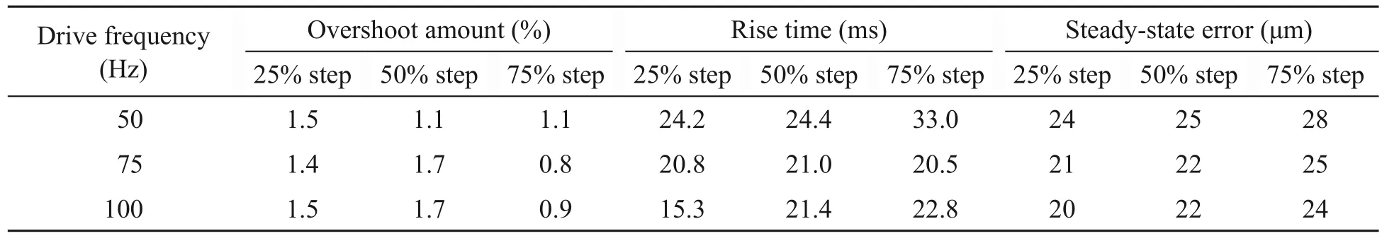
Table 4 Dynamic and static performance of the DHPV affected by drive frequency
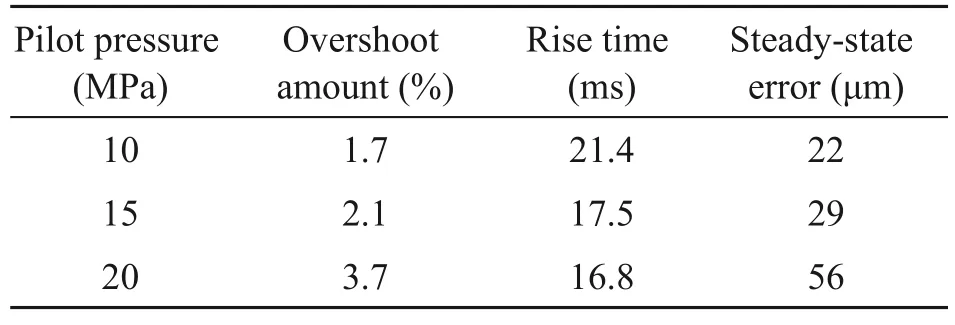
Table 5 Dynamic and static performance of the DHPV affected by pilot pressure
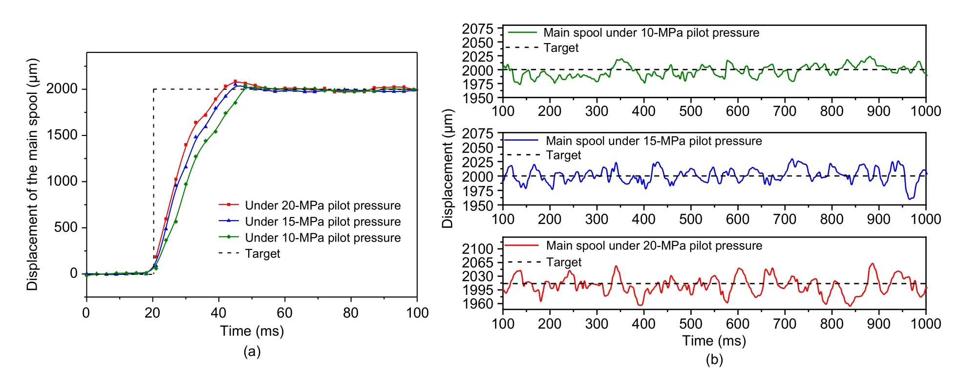
Fig.15 Dynamic and static performance of the DHPV under different pilot pressures:(a) displacement dynamic characteristics;(b)displacement steady-state characteristics
According to the above experimental analysis,with the increase of pilot supply pressure,DHPV has a better fast response performance and takes a shorter time to reach the target displacement.However,the overshoot also increases,and the pause amplitude is larger when the spool is stable at the target position.Because the DHPV uses the pilot of discrete fluid to drive the main spool,the pressure shock caused by flow pulsation causes the main spool to vibrate continuously,which affects the flow output and changes the oil chamber pressure.The stable fluctuation range of the spool may be caused by performance differences between HSVs,the delay of control signals,and the interference of sensor signal acquisition.
Therefore,the steady-state characteristics of the DHPV need to be further improved in situations with high requirements for flow or pressure control accuracy.
5 Conclusions
This paper proposes a switching pilot technology using two independent HSVs,which avoids the dead zone of the pilot stage and improves the dynamic response performance and control accuracy of the main valve.After analyzing the working principle of the DHPV,mathematical modeling is carried out.According to the theoretical analysis and experimental results,the following conclusions can be drawn:
(1) The scheme of switching pilot technology proposed in this paper is shown to be feasible through theoretical analysis and experimental verification.
(2) As the oil supply pressure of the pilot stage increases,the flow gain is improved so that the dynamic response performance can be optimized by 21.5%.However,it will cause a larger steady-state error.
(3) Increasing the frequency of the pilot stage will reduce the output oil volume in each switching cycle,so that the flow ripple in the control chamber can be reduced,and the steady-state error can be controlled within 20 μm,which meets the high-precision control requirements of the flow.
(4) Switching pilot technology shows rapid dynamic performance and stable static characteristics,proving that it has a huge potential for application.
Acknowledgments
This work is supported by the Open Foundation of the State Key Laboratory of Fluid Power and Mechatronic Systems(No.GZKF-201906),the“Pioneer”and“Leading Goose”R&D Program of Zhejiang Province,China (No.2022C01132),the Natural Science Foundation of Zhejiang Province,China(No.LQ21E050017),and the China Postdoctoral Science Foundation(Nos.2021M692777 and 2021T140594).
Author contributions
Qi ZHONG designed the research.Ti-wei JIA processed the corresponding data.En-guang XU wrote the first draft of the manuscript.Bin ZHANG helped to organize the manuscript.Hua-yong YANG and Yan-biao LI revised and edited the final version.
Conflict of interest
Qi ZHONG,En-guang XU,Ti-wei JIA,Hua-yong YANG,Bin ZHANG,and Yan-biao LI declare that they have no conflict of interest.
 Journal of Zhejiang University-Science A(Applied Physics & Engineering)2022年4期
- Journal of Zhejiang University-Science A(Applied Physics & Engineering)的其它文章
- Practice of flow control and smart valves
- Eccentric actuator driven by stacked electrohydrodynamic pumps
- Analysis of fretting wear behavior of unloading valve of gasoline direct injection high-pressure pump
- Data-driven fault diagnosis of control valve with missing data based on modeling and deep residual shrinkage network
- Mechanism analysis and evaluation of thermal effects on the operating point drift of servo valves
- Hydraulic directional valve fault diagnosis using a weighted adaptive fusion of multi-dimensional features of a multi-sensor