Experimental study on anti-penetration mechanism of bolted composite protective structure with limited span under impact of lowvelocity projectile
Yu-jia Liu ,Dian Li ,Hai-liang Hou,Zhu-jie Zhao,Yue Xie
College of Naval Architecture and Ocean Engineering,Naval University of Engineering,Wuhan,430033,China
Keywords:Impact dynamics Composite protective structure Bolt joint Ballistic test Failure modes
ABSTRACT In order to study the influence of the bolt joint mode on low-velocity projectiles penetrating the composite protective structure,two bolt joint models which connect the composite target to the fixed frame were designed,the ballistic test of the bolted composite protective structure with limited span was carried out,and the bearing and failure characteristics of the bolted region,as well as the energy dissipation of each part of the structure,were analyzed.The results show that in the condition of lowvelocity impact,there are three failure modes for the bolted composite protective structure subjected to projectile penetration,including failure of the impact point of the composite target,failure of protective structure connecting components and failure of the holes in the bolted region of the composite target;the failure mode of bolt holes in the bolted region has a great influence on the protection performance,and the allowable value of the bearing capacity of the bolted region depends on the sum of the minimum failure load in the failure modes and the friction force;shear-out failure occurring in the bolt holes in the bolted region exerts the greatest effect on ballistic performance,which should be avoided;When simultaneous failure occurs in the bolted region and the free deformation region of the composite protective structure,the energy absorption per unit surface density of the composite protective structure reaches the maximum,which can give full play to its anti-penetration efficiency.
1.Introduction
With the growing demand for lightweight protective structures,composites gradually take the place of traditional metal materials because of their higher weight efficiency[1-3].Among them,ultrahigh-molecular-weight polyethylene (UHMWPE) fiber is a composite with very low density [4],ultra-high tensile strength and large failure strain [5,6],having broad application prospects in warship protection.To fully understand the ballistic mechanism of the composite protective structure,scholars in relevant fields have done much research [7-9].The results show that fiber tensile fracture,delamination,matrix damage and other failure modes will occur in the fiber-reinforced composite target during projectile penetration [10-12].This is a typical“soft”protective structure[13],realizing the blocking of the projectile mainly through its own deformation and failure to dissipate the projectile's kinetic energy,which can well protect the low-velocity blunt-nosed projectile.
In existing research,only deformation or failure of the penetrated region are considered in general,and the target boundary is merely regarded as simply supported or fixed supported boundary,and thus the possible deformation or failure at the boundary of the composite target is ignored[14-16].In fact,under the impact of a low-velocity projectile,the deformation region usually extends to the structure boundary,and the boundary connection form and strength are very important to protection performance[17].Due to its special material properties,the composite target cannot be directly connected with the fixed support structure by welding like the metal target,so it is necessary to use a connector as the medium to realize the connection.“Fixture-clamp plate”is used as a simple way of connection in the ballistic impact test.Zhang [18],Nguyen[19]and Hazell[20]connected the composite target with the fixed support structure through the joint action of bolts and the clamp plate;the friction force between the target and the clamp plate provided boundary support for the free deformation region of the target.Cline[21]increased the friction between the target and the laminates by adding sandpaper on the clamp plate,thus increasing the reliability of boundary connection.The“fixture-clamp plate”connection maintains the in-plane integrity of the composite target,but has a weak connection strength,so it is not suitable for connection within the composite protective structure.
To improve the connection strength between the composite target and the fixed support structure,Xu[22],Cai[23]and Liu[24]adopted the bolt joint mode by first opening holes at the boundary region of the target and then using bolts and the fixed frame to connect the target and the supporting structure.Such connection provided boundary support for the free deformation region of the target through bolts and friction force,and the connection strength greatly increased compared with the“fixture-clamp plate”mode.Therefore,this way of connection is suitable for composite protective structures.However,when the composite plate is connected by bolts,holes on the plate will damage its in-plane integrity,and when the in-plane load is large,bolt holes are prone to deformation and failure [25,26].The ballistic impact test carried out by Shen et al.[27] showed that the bolt holes of bolted UHMWPE target plate subjected to projectile penetration experienced deformation and failure.However,the effect of bolt hole deformation and failure on the ballistic performance of the composite plate is rarely reported.
In the experimental work,UHMWPE laminates were used as the target,meanwhile,two bolt joint modes were designed to connect the target with the fixed frame,which formed the composite protective structure.The ballistic impact test of the model projectile was carried out.The deformation and failure modes as well as the ballistic performance of the composite protective structure with the two bolt joint modes were analyzed and compared.The calculation method for bearing capacity of the bolted region was obtained through the stress analysis of this region.This paper proposes the design objective of maximizing the ballistic performance of the composite protective structure from the perspective of energy dissipation.
2.Experimental procedure
2.1.Test set-up
The layout of the test site is shown in Fig.1.The 76 mm smoothbore gun was used to launch the projectile,and the on-off target net velocity measurement system and high-speed camera were employed to measure the velocity of the projectile and its flight attitude simultaneously.
The target net speed measuring system was set between the smoothbore gun and the target.The system is composed of the target net,signal acquisition equipment,signal processing and power supply circuit,etc.The high-speed camera was placed in the safety zone on the side of the test site,and took photos through the whole process of the model test so as to verify the measurement results of the target net speed measuring system meanwhile to observe the projectile's penetration process and its hitting attitude and measure the residual velocity of the projectile.
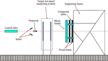
Fig.1.Schematic diagram of projectile impact test site.
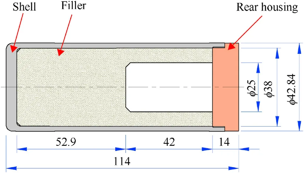
Fig.2.Schematic diagram of projectile model (all dimensions are in mm).
2.2.Projectile
The projectile is composed of the shell,filler and rear housing as shown in Fig.2.The overall length of the projectile was 114 mm,the diameter was 42.84 mm,and the total mass of the projectile was 484 g.The shell material was D6AC steel,whose length was 106 mm,front end thickness was 5.1 mm,and a mass of 297 g.The filler was PPS plastic with a mass of 136 g.The rear housing was made of aluminum with a mass of 51 g.The material properties of each part of the projectile are shown in Table 1.
A split aluminum sabot was set around the projectile(see Fig.3).During flight,the sabot was separated due to air resistance and blocked by the blocking plate arranged in front of the target.
2.3.Protective structure
The protective structure target plate was composed of several stacking UHMWPE laminates without bonding.Each 4 mm UHMWPE laminate was made from 16 layers of fiber unidirectional cloth stacked in 0and 90in turn and pressed together.The initial thickness of the single-layer fiber unidirectional cloth was 0.253 mm,and the area density was 240 g/m.The UHMWPE laminates were connected with the fixed frame by bolt joint,which together formed the composite protective structure.According to whether the normal direction of the target plate is constrained by the fixed frame,the in-plane region of the composite target can be divided into two parts:the free deformation region and the bolted region,as shown in Fig.4.
To study the influence of bolt joint on the ballistic performance of the composite protective structure,protective structures with two different bolt joint modes were designed:
(1) Bolt joint model 1(BJ1):UHMWPE laminates with the plane size of 600 mm×600 mm were used as the target.The outer length of the fixed frame was 600 mm,and a 400 mm × 400 mm square hole was opened in the middle region.The thickness of the frame was 30 mm.48 bolts were used to connect the target and the frame closely,as shown in Fig.5 (a).The material properties of UHMWPE laminates,Fixed frame and Bolts are shown in Table 2 and Table 3.
(2) Bolt joint model 2(BJ2):UHMWPE laminates with the plane size of 500 mm×500 mm were used as the target.The outer length of the fixed frame was 500 mm,and a 400 mm × 400 mm square hole was opened in the middle region.The thickness of the fixed frame was 10 mm.16 bolts were used to connect the UHMWPE laminate and the fixed frame,as shown in Fig.5 (b).
Although the composite target used in the two bolt joint modes had different in-plane sizes,their free deformation regions were of the same size.Meanwhile,to mitigate the influence of manufacturing process on the strength of UHMWPE laminates with different thicknesses,the thickness of each single laminate was 4 mm despite their different plane sizes.The thickness of the protective structural target was adjustable by increasing and reducing the number of laminates.
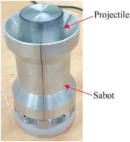
Fig.3.Schematic diagram of projectile and sabot.
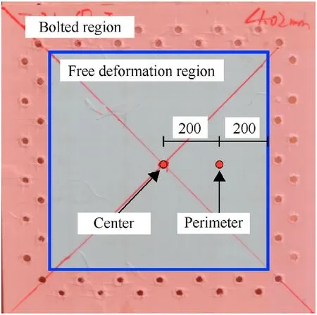
Fig.4.Composite target region division.
2.4.Brief test results
A total of 8 valid ballistic tests of low-velocity projectile penetration of the protective structure were carried out.The working conditions and brief results of each test are shown in Table 4,and the penetration position is shown in Fig.4.The position of impact point is shown in Fig.4.
3.Experimental results and discussion
3.1.Fixed frame deformation
Due to the large in-plane size,big thickness and high overall structural stiffness of the fixed frame used in BJ1,no obvious plastic deformation occurred under the in-plane load generated by projectile penetration,as shown in Fig.6 (a).However,with small inplane size,small thickness and low overall structural stiffness,the fixed frame in BJ2 saw obvious plastic deformation under the inplane load caused by projectile penetration.The largest deformation appeared in the middle region of the fixed frame,which became smaller as it gets closer to the corner,as shown in Fig.6(b).
Increasing the structural stiffness of the fixed frame through increasing the thickness and in-plane size can effectively reduce the structural deformation of the fixed frame.

Table 1 Material parameters of projectile component.
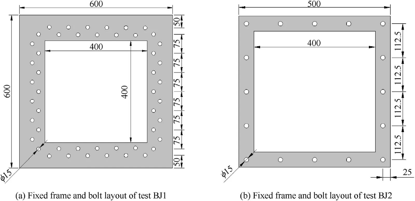
Fig.5.Schematic diagram of fixed frame and bolt arrangement.

Table 2 Material properties of UHMWPE laminates [24].

Table 3 Material properties of fixed frame and bolts.

Table 4 Impact test data and results.
3.2.Bolt joint model 1
When the projectile penetrates the center of the target,the typical failure morphology of BJ1 target is shown in Fig.7.Subjected to projectile penetration,BJ1 target experienced four types of damage morphology,namely,fiber tensile fracture,laminate delamination,bearing deformation of bolt holes and fiber debonding and pulling out.When the initial velocity of the projectile exceeded the ballistic limit of the target,the projectile penetrated through the impact point,and fiber tensile fracture occurred in the through-thickness direction of the target,as shown in Fig.7.Therefore,the fiber tensile fracture at the impact point is the main reason for the failure of BJ1 target.
The shape of dynamic deformation cone was observed on the back surface of the composite target,which formed due to the projectile pushing the impact point forward and the rest of the target moving forward under the action of transverse waves.With the expansion of the propagation range of transverse waves,the bottom area of the dynamic deformation cone also increased,and finally covered the whole free deformation region of the target.The expansion process of the cone is shown in Fig.8.By observing the final morphology of the cone,it was found that the shape and size of the cone top were close to those of the front end of the projectile;the size of the cone bottom was approximately that of the free deformation region of the composite target;the side edges approximately coincided with the diagonal line of the free deformation region of the composite target.When the initial velocity of the projectile varied,the shape of the dynamic deformation cone changed as well.
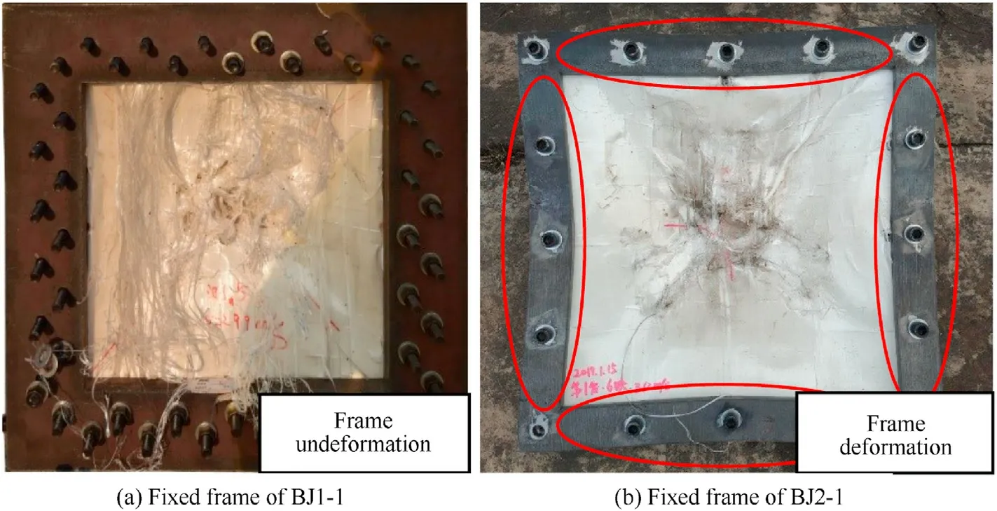
Fig.6.Fixed frame deformation after penetration.
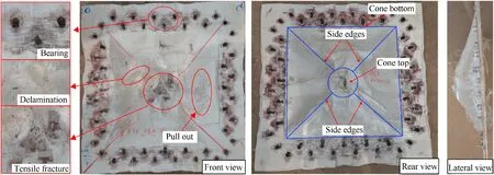
Fig.7.Target plate deformation failure in test BJ1-2.
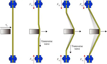
Fig.8.Dynamic deformation cone formation process.
When the velocity of the projectile was higher than the ballistic limit velocity of the target,the projectile penetrated through the entire composite protective structure target,and obvious fiber tensile fracture occurred in the area around the perforation.The overall shape of the dynamic deformation cone was complete featuring clear lines of the side edges,a break at the top,the bottom extending to the whole free deformation region,and evident depression on the side of the cone,as shown in Fig.7.The reason is:when the initial velocity of the projectile is higher than the ballistic limit of the composite target,the target will be overstretched,and the structural morphology of the dynamic deformation cone will be“strengthened”during the penetration process.As perforation appears in the impact point,strain release will occur in the overstretched area of the target,accompanied by a certain degree of springback,thus surface depression forming on the side of the dynamic deformation cone.This can further highlight the morphology of the side edges of the dynamic deformation cone.
When the projectile's velocity was lower than the limit velocity of the target,the projectile only penetrated part of the composite target,and then sprang back from the target.Fiber tensile fracture also occurred at the holes in the part of the area penetrated by the projectile on the impact point of the target,and the dynamic deformation cone structure kept intact,as shown in Fig.9.The reason is:as the velocity of the projectile is lower than the ballistic limit of the target,target overstretching is small,and thus almost no“springback”appears in the stretching area of the target,so the side of the dynamic deformation cone still keeps“convex”.At the same time,the side edges of the dynamic deformation cone in Fig.9 are not as obvious as those in Fig.7 due to the small overstretching of the target.
When the impact point deviated from the center,the deformation and failure morphology of the target were significantly different,as shown in Fig.10.Tensile failure of the target occurred at the penetration position on the impact point of the target,and oblique perforation appeared in the target.In addition,the bolt holes on the side near the impact point experienced severe bearing failure,boundary tear occurred at the back plate,and part of the target curled backward,while the bolt holes far away from the impact point experienced small deformation,and the bolted region also kept intact.At the same time,fiber debonding and pulling out at the part near the impact point was more serious than at the part far away,as shown in Fig.10.
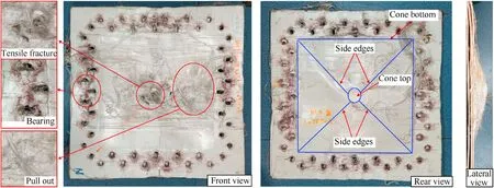
Fig.9.Target plate deformation failure in test BJ1-4.

Fig.10.Target plate deformation failure in test BJ1-3.
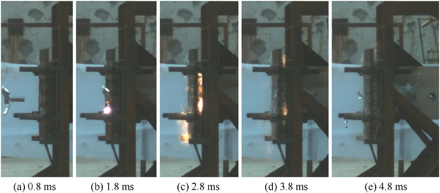
Fig.11.Projectile penetration process captured by high-speed photography in test BJ1-3.
Fig.11 shows the high-speed photographs in BJ1-3 working condition.From the photographs,it can be seen that the projectile does not come out of the back of the target after impacting the target,but the rear housing of the shell falling off the projectile passes through the back of the target.Combined with the highspeed photographs,the process of projectile penetration is analyzed as follows.The projectile impacts the target,pushing the impact point to move forward.Since the distance between this area and the boundary of both sides of the target is not equal,the force on the projectile is unbalanced horizontally,causing the projectile to overturn in the horizontal direction.And tensile failure also appears in the impact area subjected to projectile penetration.In the penetration process,the target boundary near the penetration position bears more in-plane loads.Because the in-plane load exceeds the range the target boundary can bear,boundary tear occurs on the back surface,which is further connected with the hole of fiber tensile failure on the impact point to form an oblique perforation through the thickness direction of the target.When the perforation forms,the projectile deflects and cannot pass through it.After the projectile impacts the target,the connection between the shell and the rear housing fails due to the action of internal stress.When the projectile overturns,the rear housing is thrown out and the target with torn boundary is impacted,which finally leads to the curling of part of the target.
Therefore,when the projectile penetrates the peripheral position,the horizontal (vertical) unbalanced force produced by the impact will have the following two effects:1.The horizontal (vertical)uneven force will cause the projectile to overturn horizontally(vertically),which will increase the penetration area of the projectile,and objectively reduce the penetration performance of the projectile;2.The uneven horizontal force will increase the load at the boundary near the penetration position,which can easily lead to the tear failure of the boundary,and reduce the protection performance of the composite target.
3.3.Bolt joint model 2
The deformation and failure morphology of BJ2 target with different thicknesses is shown in Fig.12.The target experienced four damage modes,namely,fiber tensile fracture,laminate delamination,shear-out failure at the bolted region and fiber pulling out.When the initial velocity of the projectile exceeded the ballistic limit of the target,shear-out failure appeared in the bolt holes of the composite target,and the failure area of the bolt holes expanded to the target boundary;the bolted region failed as well,as shown in Fig.14.Therefore,the failure of the bolted region caused by the shear-out failure of the holes is the main reason for BJ2 target plate failure.
In BJ2-1,due to the big thickness of the target and strong bearing capacity of the holes in the bolted region,during the penetration process,a small number of holes experienced shear-out failure,the bolted region did not fail,and the in-plane load of the target was transferred to the fixed steel frame through the bolts and the holes.However,the steel frame experienced structural plastic deformation under the in-plane load of the target due to its low stiffness.At the same time,part of the target at the impact area failed under projectile penetration,and obvious fiber tensile fracture appeared on the impact point,as shown in Fig.12.
In BJ2-2,due to the decreased thickness of the target and reduced bearing capacity of the holes in the bolted region of the target,during the penetration process,some of the holes experienced shear-out failure and the failure area extended to the boundary of the target,resulting in partial failure of the bolted region.The in-plane load of the target plate was not effectively transferred to the steel frame through the bolts and the holes.Therefore,the plastic deformation of the fixed frame was less severe than that of the fixed frame in BJ2-1.Obvious fiber tensile deformation also appeared in the impact area of the target,but the failure depth of the target was clearly less than that in BJ2-1,as shown in Fig.13.
In BJ2-3,as the target thickness is the smallest among these cases,almost all the bolt holes of the target experienced shear-out failure,and the failure area extended to the boundary of the target.All the bolted region failed,and the target was pulled out from the fixed frame.Compared with BJ2-2,the damage of the target at the impact area in BJ2-3 was lighter,but target plate delamination was more severe,as shown in Fig.14.
Like BJ1 target,the dynamic deformation cone formed on the back surface of the target under the push of the projectile,and the cone bottom extended to the boundary of the free deformation region of the target as transverse waves propagate within the target.When the thickness of the target was large,as the bolted region of the target did not fail,the cone bottom morphology remained intact,and a complete dynamic deformation cone was observed on the back surface,as shown in Fig.12.However,when the thickness of the target plate was small,due to the shear-out failure area of some or all bolt holes extending to the target boundary,the bolted region partially or completely failed,and the dynamic deformation cone on the back surface of the target tilt toward the direction of the failed boundary.By observation,the shape of the dynamic deformation cone was incomplete or even indistinguishable after the test,as shown in Figs.13 and 14.
4.The effect of bolt joint model
4.1.Force analysis of bolted region
Under the impact of the projectile,the in-plane tension Fis generated within the composite target,and the load in the impact area propagates to the edge of the target in the form of stress waves.When the internal stress wave propagates to the boundary of the target,the bolt holes bears the load of in-plane tension.When the bearing capacity of the holes Fexceeds the in-plane tension F,the holes will not deform and fail,and the in-plane tension will be further transmitted to the steel frame through the bolts.When the strength of the holes or the fixed frame is insufficient,bolt fracture or large plastic deformation will occur to the fixed frame;when the bearing capacity of the bolt holes Fis lower than the in-plane tension F,the holes will deform and fail under the action of inplane tension.When the deformation area of the bolt holes extends to the boundary of the target,it will lead to the failure of the bolted region.Therefore,three failure modes may appear in the process of low-velocity projectile penetration of the bolted composite protective structure with limited boundary.
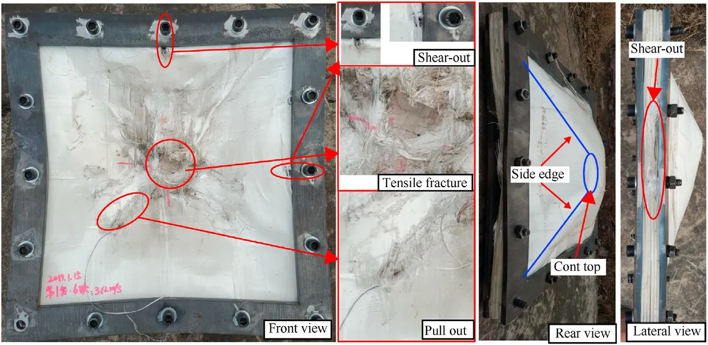
Fig.12.Target plate deformation failure in test BJ2-1.
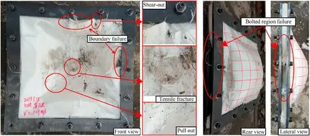
Fig.13.Target plate deformation failure in test BJ2-2.

Fig.14.Target plate deformation failure in test BJ2-3.
Mode 1:failure of the impact point of the composite target.When the composite target is penetrated by the projectile,tensile or shear failure occurs in the impact point,forming a perforation partially or completely through the thickness of the target,as shown in Figs.7 and 9.Failure of the impact point of the composite target appears in both BJ1 and BJ2,which is the dominant failure mode of the composite target in current ballistic performance research.
Mode 2:failure of protective structure connecting components(bolt fracture or fixed frame plastic deformation or failure).When the load transmitted to the bolts and fixed frame through the bolt hole area exceeds the limit load,the bolts and frame will deform and fail.In the model test for BJ2,obvious plastic deformation of the fixed frame occurred,as shown in Fig.6(b).Such deformation and failure mode can be effectively avoided by using thick and rigid frame.
Mode 3:failure of the bolt holes in the bolted region of the composite target.Under the action of in-plane load produced by projectile penetration of the composite target,possible failure modes of the bolt holes are as follows:1.bearing;2.shear out;3.net tension;4.cleavage [29],as shown in Fig.15.Because the bolted region provides in-plane support for the whole composite target by the contact between the bolt hole and the bolt,when the failure area of the holes extends to the boundary of the target plate,the bolted region will fail and the composite target will separate from the fixed frame.
The actual failure mode of the protective structure in this test may be one of the above three modes or their combinations.

Fig.15.Failure modes of composite joints.
In this test,bolt holes of BJ1 target experienced bearing failure,while those of BJ2 target experienced shear-out failure.According to the test results,although bearing failure occurred in the holes of BJ1 target,the expansion range of the bolt hole failure area did not reach the target boundary,and the bolted region did not fail,which could still provide effective boundary support for the free deformation region.However,shear deformation occurred in the holes of BJ2 target,and the damage of the bolted region of the target was more serious than that of BJ2 target.The bolted region in BJ2-3 failed completely,and the composite target was pulled out from the fixed frame.
Assuming that each bolt hole in the composite target bears the same in-plane load during the penetration process,the maximum in-plane load(allowable value of bearing capacity F)of all holes in the bolted region of the target is calculated as follows.
(1) In case of bearing failure of bolt holes,the bearing failure load of bolt holes Fis expressed as [30]:

where n is the number of holes in the bolted region of the composite target;σis the in-plane compressive strength of the composite target;d is the diameter of the bolt hole;h is the thickness of the composite target;e is the distance between the hole and the target boundary;for BJ1 target,e is the average value of the distance between the two rows of bolts and the target boundary,62.5 mm;for BJ2 target,e is 25 mm;λ is an e/d-related coefficient,and for BJ1 and BJ2 targets,λ is 0.97 and 0.9 [30] respectively.
(2) In case of shear-out failure or cleavage,the shear-out failure load on the bolt holes of the target Fis expressed as [31]:

where σis the in-plane shearing strength of the composite target.
(3) In case of net tension failure of the composite target,the tensile failure load on the bolt holes of the target Fis expressed as [31]:

where σis the in-plane shearing strength of the composite target and s is the distance between bolt holes.
When bolt holes and the fixed frame are used to connect the composite protective structure,the upper and lower surfaces of the composite target are also affected by the friction force from the frame,F.The value of Fis given by:

where η is the tensile safety factor of the bolt,0.5 ≤η ≤0.7,which is taken as 0.5 in this article;μis the friction coefficient between the steel frame and the composite target,and the value is 0.2[32];σis the yield strength of the bolt;Ais the effective cross-sectional area of the bolt,whose value is taken as 115 mm[28].
When the load on the bolt hole exceeds the failure load of any of the above deformation failure modes,the bolt holes of the target will deform and fail.Therefore,the allowable value of the bolt holes Fis expressed as:
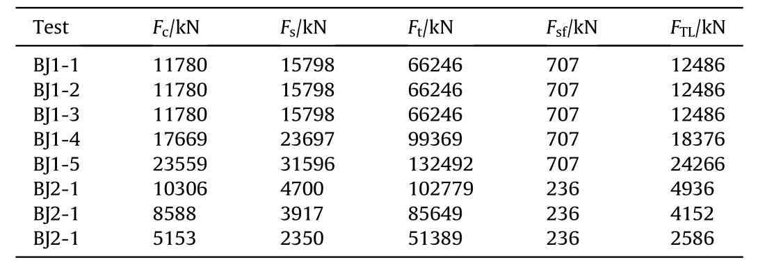
Table 5 Comparison of failure loads.

According to existing material parameters,the allowable bearing capacity of the holes in the bolted region of the composite target,F,under various working conditions is calculated and compared as shown in Table 5.
According to the table,since the threshold of bearing failure of BJ1 target is the lowest,bearing failure is the dominant failure mode of bolt holes in BJ1 target,while for BJ2 target,the threshold of shear-out failure is the lowest,so shear-out failure is the dominant failure mode for BJ2 target.The calculated dominant failure modes of bolt holes are in good agreement with experimental results.From formula 1 and 2,compared with the bearing failure load F,the shear-out failure load Fis more affected by the ratio of edgedistance-to-hole diameter (e/d).Increasing e/d can effectively improve the value of shear-out failure load F,so shear-out failure of bolt holes can be avoided.
It is worth noting that the actual structural failure mode is generally one of modes 1,2,and 3.The final failure type will be affected by the number of bolts,the thickness of the composite board,the size of the frame,and the tightening force of the bolts.
4.2.Analysis of energy absorption
During projectile penetration,the energy dissipated by the composite target Eand the energy dissipated per unit areal density Eare expressed as:

where mis the mass of the projectile;vis the initial velocity of the projectile;vrepresents the residual velocity of the projectile;when the composite target is not penetrated,the residual velocity is very small,which can be regarded as 0;ρis the areal density of the target.
The energy dissipation per unit areal density of the protective structure at the time of failure of the protective structure with two bolt joint modes is selected as the evaluation standard for protection performance,as shown in Fig.16.The energy dissipation per unit areal density of BJ1 is 2567.5 J·m/kg (the average value of energy dissipation per unit areal density in BJ1-1,BJ1-2 and BJ1-3),and the energy dissipation per unit areal density of BJ2 is 1606.8 J·m/kg(the energy dissipation per unit areal density of BJ1-3).The energy dissipation per unit areal density of BJ1 is 59.8%higher than that of BJ2,and the ballistic performance of BJ1 protective structure is better.
Since the total energy dissipation of the composite target consists of two parts:energy dissipation in the free deformation region and in the bolted region,with the former as the dominant one.Therefore,according to whether energy dissipation in the two regions reaches the limit,there are four conditions for the composite protective structure target:
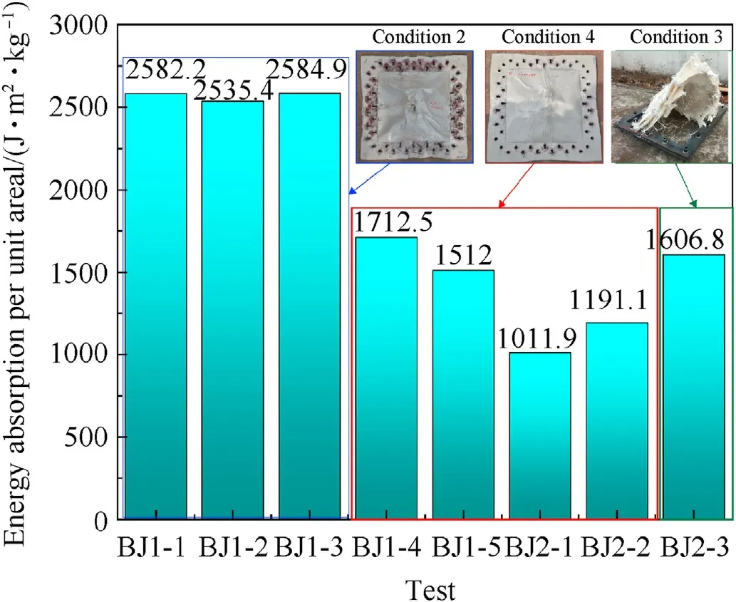
Fig.16.Comparison of energy dissipation per unit surface density in various tests.
Condition 1:when energy dissipation in the free deformation region and in the bolted region reaches the limit (the two regions fail simultaneously),the protection efficiency of the structure is the best,but this is an ideal state,which is difficult to realize and did not appear in the ballistic test;
Condition 2:energy dissipation reaches the limit in the free deformation region but not in the bolted region,meaning the protection efficiency is not brought into full play in the bolted region,as shown in the working conditions of BJ1-1,BJ1-2 and BJ1-3;
Condition 3:energy dissipation reaches the limit in the bolted region but not in the free deformation region.As the protection efficiency is not fully displayed in the free deformation region,the overall ballistic performance of the composite protective structure is lower than that in Condition 2,such as in the case of BJ2-3,which should be avoided in the design;
Condition 4:energy dissipation in both the free deformation region and the bolted region does not reach the limit,so the protection efficiency of the protective structure is not fully displayed,such as in BJ1-4 and BJ1-5.
In the actual design of the composite protective structure,energy dissipation in the free deformation region of the target should not be the only consideration;energy dissipation in the bolted region is also supposed to be included.Under the premise of achieving effective protection of the projectile,Condition 1 should be taken as the design goal,and the energy dissipation of the free deformation region and the bolted region should be fully utilized to improve the overall protection efficiency of the composite protective structure.
5.Conclusion
The ballistic impact test of low-velocity projectile penetration was carried out to study the influence of bolt joint on the ballistic performance of the composite protective structure.Different failure modes of the composite protective structure target with two bolt joint modes were compared.The force on the bolted region and energy dissipation of the protective structure target were analyzed:
1.There are three failure modes for the bolted composite protective structure subjected to projectile penetration:failure of the impact point of the composite target;failure of the connecting components (bolts/frame);failure of holes in the bolted region of the composite target plate.The actual failure mode of the bolted composite protective structure may be one of the above failure modes or their combinations;
2.Compared with bearing failure,when shear-out failure occurs in the holes in the bolted region,the failure area tends to expand to the target boundary,resulting in the failure of the bolted region,which will greatly degrade the ballistic performance of the composite protective structure.Therefore,shear-out failure of bolt holes should be avoided in the design of the composite protective structure.
3.Through the stress analysis of the bolt holes in the bolted region of the target,the calculation method of the allowable bearing capacity of the bolted region Fis obtained.Because Fdepends on the sum of the friction force and the minimum value among the bearing failure load F,the shear-out failure load Fand the tensile failure load F,to avoid the shear-out failure of the holes,it is necessary to ensure that the shear-out failure load Fis higher than the bearing failure load Fin the design of the bolted region of the composite protective structure;increasing the hole-edge distance is the optimal way.
4.From the perspective of energy dissipation,the energy dissipation of the composite protective structure target contains two parts:energy dissipation in the free deformation region and the bolted region.To maximize the protective efficiency of the protective structure,failure should occur in the free deformation region and the bolted region of the composite protective structure simultaneously.In that condition,energy dissipation in the free deformation region and the bolted region will be close to the limit.
This work was supported by the National Natural Science Foundation of China [grant nos.51679246].
The authors declare that they have no known competing financial interests or personal relationships that could have appeared to influence the work reported in this paper.
This research was done with the financial support of the National Natural Science Foundation of China (Grant nos.51679246).The authors wish to express their gratitude to Qing Yu for his selfless help during the experimental tests.
- Defence Technology的其它文章
- Ultra-lightweight CNN design based on neural architecture search and knowledge distillation:A novel method to build the automatic recognition model of space target ISAR images
- Dense copper azide synthesized by in-situ reaction of assembled nanoporous copper microspheres and its initiation performance
- Ballistic impact response of resistance-spot-welded (RSW) doublelayered plates for Q&P980 steel
- Calculating detonation performance of explosives by VLWR thermodynamics code introduced with universal VINET equation of state
- Design and motion analysis of reconfigurable wheel-legged mobile robot
- A Multi-UCAV cooperative occupation method based on weapon engagement zones for beyond-visual-range air combat

