Prediction of quantum anomalous Hall effect in CrI3/ScCl2 bilayer heterostructure
Yuan Gao(高源) Huiping Li(李慧平) and Wenguang Zhu(朱文光)
1International Center for Quantum Design of Functional Materials(ICQD),Hefei National Laboratory for Physical Sciences at the Microscale,University of Science and Technology of China,Hefei 230026,China
2Department of Physics,University of Science and Technology of China,Hefei 230026,China
Keywords: quantum anomalous Hall effect,two-dimensional heterostructure
1. Introduction
The quantum anomalous Hall effect (QAHE)[1]is the manifestation of topological electronic structure characterized by a nonzero Chern number (CN) and chiral edge electronic states. Aside from fundamental interest, the QAHE also has great promise in development of low-power-consumption spintronic devices for practical applications owing to its dissipationless transport nature, which has stimulated tremendous efforts for its experimental realization since the first theoretical model was proposed by Haldane in 1998.[1]Following a theoretical recipe,[2]the experimental realization was first achieved in magnetically doped three-dimensional topological insulators in the family of Bi2Se3,[3–8]while the highest temperature achieved so far is only 2 K,[8]due to inevitable degradation of sample quality with the complexity caused by the magnetic doping. More recently, the QAHE was realized in a layered compound MnBi2Te4[9–11]with a record temperature of 13 K and an external magnetic field required to align the intrinsically antiferromagnetically coupled MnBi2Te4layers to be ferromagnetic (FM).[11]In addition, twisted bilayer graphene was also recently reported to achieve the QAHE experimentally at 1.6 K.[12]However,searching for new QAHE systems particularly with substantially enhanced the critical temperature is highly demanded for practical applications but still a grant challenge in this field.
Recent discovery of two-dimensional (2D) ferromagnetic materials provides new opportunities for this endeavor.By constructing multilayer van der Waals heterostructures,several new QAHE systems were theoretically proposed, including the ones consisting of a layered topological insulator and a 2D ferromagnetic layer, e.g., arranged by publishing time,graphene/BiFeO3,[13]graphene/RbMnCl3,[14]graphene/Cr2Ge2Te6,[15]MnBi2Te4/GeBi2Te4,[16]MnBi2Se4/Bi2Se3,[17]CrI3/Bi2Se3,[18]CrBi2Se4/Bi2Se3,[18]germanene/Cr2Ge2Te6,[19,20]graphene/CrBr3,[21]MnBi2Te4/ Sb2Te3,[22]MnBi2Te4/CrI3,[23]graphene/MnPSe3,[24]graphene/NiI2,[25]MnBi2Te4/VBi2Te4[26]or MnBi2Te4/Bi2Te3[27]and the ones consisting of two ferromagnetic layers MnNF/MnNCl.[28]
In this work, we propose a 2D van der Waals (vdW) bilayer heterostructure constructed by stacking two topologically trivial ferromagnetic(FM)monolayers CrI3and ScCl2to realize the QAHE state. Based on first-principles calculations within the framework of density functional theory(DFT),the topological nature of the heterostructure is revealed to be attributed to an interlayer band inversion between the monolayers,and it critically depends on the structural symmetry of the stacking configuration. Our calculation shows that the pristine bilayer heterostructure has a sizable topologically nontrivial band gap of 4.5 meV.We further demonstrate that the band gap can be increased nearly linearly by the application of a perpendicular external pressure and reaches 8.1 meV at 2.7 GPa,and the application of an external out-of-plane electric field can also modulate the band gap and convert the system back to being topologically trivial via eliminating the band inversion.An effective model is developed to describe the evolution of
the topological phases observed in this bilayer system.
2. Computational methods
The first-principles DFT calculations were performed based on the projector augmented wave(PAW)formalisms[29]with the exchange and correlation functional in the form of PBEsol[30]as implemented in the Viennaab initiosimulation package (VASP).[31,32]A plane wave basis cutoff of 400 eV was used. To model the 2D heterostructure,the supercell contains a monolayer of an 1×1 CrI3stacking with a monolayer of a 2×2 ScCl2with a vacuum region of 30 ?A.AΓ-centered 8×8×1 mesh was used fork-point sampling.[33]HubbardU= 3 eV and 1 eV were added to the partially filled 3d transition-metal elements Cr and Sc, respectively, to capture the local Coulomb interaction. The van der Waals corrections as parameterized in the semiempirical DFT-D3 method[34]were included. The electronic convergence criterion was set to 10-6eV,and atomic structures were fully relaxed until the forces on all atom were smaller than 0.005 eV/?A.The Hamiltonian matrixes in the Wannier function basis were calculated by Wannier90,[35]which served as an input of PythTB to calculate the Berry curvature as well as the CN and the surface states with WannierTools.[36]To verify the dynamical stability of 2D monolayer ScCl2, phonon dispersion analysis was performed using VASP and phonopy,[37]in which the structure was fully relaxed until the energy and the forces were converged to 10-8eV and 10-6eV/?A,respectively.
3. Results and discussion
3.1. Atomic structure and magnetism of monolayer CrI3 and ScCl2
CrI3is a 2D vdW stacked layered material,and its monolayer has been experimentally demonstrated to be an FM insulator with a Curie temperature of 45 K.[38]As shown in Fig. 1(a), each unit cell of monolayer CrI3contains two Cr atoms, forming a honeycomb lattice, and each Cr atom covalently bonds with six neighboring I atoms, with a space group ofPˉ31m. Monolayer ScCl2was also predicted to be an FM insulator.[39,40]As shown in Fig.1(b),each monolayer of ScCl2is composed of three atomic layers,and the atoms in each atomic layer contain only one element forming a triangular lattice, among which the Sc layer is sandwiched between the two Cl layers and the three atomic layers follow an ABA stacking sequence with the whole structure possessing a space group ofPˉ6m2. The absence of imaginary frequency in the calculated phonon spectra of monolayer ScCl2,as indicated in Fig.A1,confirms the dynamical stability of the structure. The optimized in-plane lattice constants of monolayer ScCl2and CrI3are 3.474 ?A and 6.900 ?A,respectively. Thus a 2×2 unit cell of ScCl2can perfectly match with a 1×1 unit cell of CrI3with a mismatch of merely 0.7%.
Figures 1(c) and 1(d) show the calculated band structures of monolayer CrI3and ScCl2in the FM phase, indicating that they are both FM insulators with band gaps of 1.12 eV and 0.15 eV for CrI3and ScCl2and Cr and Sc atoms carry magnetic moments of 3μBand 1μB, respectively. For CrI3, the magnetization of the whole layer prefers out-ofplane orientation with a magnetic anisotropy energy (MAE)of 1.61 meV/unit cell relative to the in-plane magnetization,while the magnetization of monolayer ScCl2slightly favors in-plane orientation with an MAE of 0.01 meV/unit cell.Band structures of monolayer CrI3and ScCl2with spin orbital coupling(SOC)are shown in Fig.B1.

Fig.1. Atomic structure and magnetism of monolayer CrI3 and ScCl2.(a)Top view and side view of CrI3. The black solid line on the top view shows the unit cell. (b) Top view and side view of ScCl2. The blue dashed line and the black solid line on the top view show the unit cell and the 2×2 unit cells,respectively. (c)and(d)The band structures of monolayer CrI3 and monolayer ScCl2,respectively,without SOC.
3.2. Stacking structure and magnetism of CrI3/ScCl2 heterobilayer
Before investigating its electronic structure,we first identify the most stable stacking configuration of an FM-coupled CrI3/ScCl2bilayer (Fig. 2(a)) by mapping out the whole 2D energy landscape (Fig. 2(b)) of the stacking registry space of the two layers sliding relative to each other. Figures 2(c)and 2(d)show the stacking configurations with the lowest and highest energies,respectively.In the highest energy configuration,Cr atoms in one of the Cr sublattices in the CrI3layer are vertically aligned with Sc atoms in the ScCl2layer and the rest Cr atoms in another Cr sublattice is aligned with the hollow sites of the ScCl2layer. In the most stable configuration with optimized in-plane lattice constant 6.937 ?A,one of the Cr sublattices is still aligned with the hollow sites of the ScCl2layer,while another Cr sublattice is aligned with the Cl atoms of the ScCl2layer. The energy difference between the highest and the lowest energy configurations is 58.05 meV/cell. The calculations with considering different interlayer magnetic structures and magnetization orientations indicate that the CrI3and ScCl2layers always favor FM coupling with the magnetization of both layers along the out-of-plane orientation,independent of the stacking configuration. For the most stable configuration, the energy of the FM state is lower than that of the interlayer antiferromagnetic(AFM)state by 5.75 meV/cell. Detailed calculation results are summarized in Table 1.

Fig. 2. Stacking structure of CrI3/ScCl2 bilayer. (a) The side view of CrI3/ScCl2 heterostructure. (b)The contour map showing the stacking energy as a function of lateral shift with respect to the highest energy stacking. The scale of axes means the relative translation fraction of the two monolayers. (c) and (d) Top views of the lowest energy stacking and the highest energy stacking,respectivley.
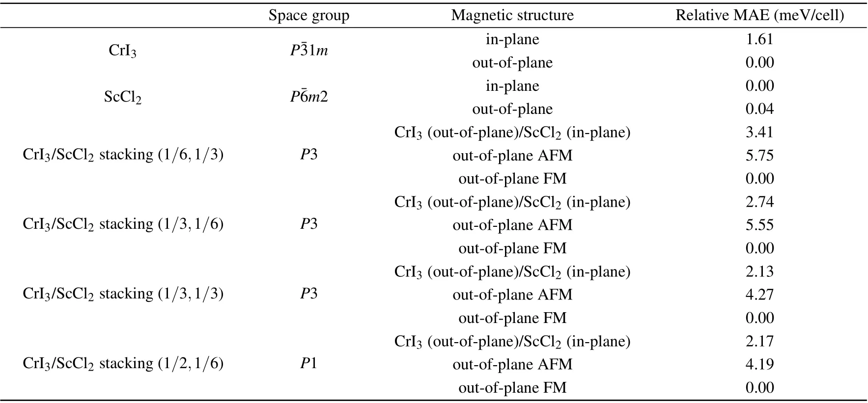
Table 1.Space groups,and magnetic properties of monolayer CrCl3,monolayer ScCl2 and bilayer heterostructure CrI3/ScCl2 with different stacking configurations. The second column shows the space groups of those systems. The third and fourth columns show relative MAE of different magnetic structures. We list stacking(1/6,1/3),stacking(1/3,1/6),stacking(1/3,1/3),and stacking(1/2,1/6)for example.For each cell discussed in this table,there are two Cr atoms and/or four Sc atoms.
3.3. Topological property of CrI3/ScCl2 heterobilayer
Figure 3(a) shows the calculated band structure of the most stable stacking configuration of the FM-coupled CrI3/ScCl2bilayer with SOC. It clearly reveals that there is indeed band inversion between the valance band of the ScCl2layer and the conduction band of the CrI3layer in the vicinity of theΓpoint. The zoomed-in band structure plot indicates a sizable band gap of~4.5 meV opened in the overlapped bands, which implies the emergence of potential topological non-trivial band structure. Detailed atomic orbital projection analysis further reveals that the inverted valence band and conduction band are both spin polarized and contributed by Sc dz2orbital of the ScCl2layer and Cr dxz+dyzorbitals of the CrI3layer, respectively. In addition, the most stable stacking configuration belongs to space groupP3, which is associated with point groupC3,and the irreducible representations of the two inverted bands atΓpoint belong to the irreducible representations table of the little co-groupGΓ ≈C3as listed in Table 2,suggesting that the two inverted bands at theΓpoint have different symmetries and thus it is expected to induce a topological phase transition.[41,42]
We calculated the CN of the most stable stacking configuration of the FM-coupled CrI3/ScCl2bilayer from firstprinciples in reciprocal space[43]with

wherenis the band index,Enkandψnkare the eigenvalue and eigenstate of bandnrespectively,vx/yis the velocity operator,andfn=1 for the occupied band. The reciprocal space distribution of the Berry curvatureΩ(k) of all occupied bands as shown in Fig.3(b)suggests a nonzero integration over the whole Brillouin zone, and the calculation indeed confirms a CN of-1, indicating that the stacking of the CrI3/ScCl2bilayer in the most stable configuration makes the system undergo a topological phase transition to the QAHE state.

Fig. 3. Band structure and topological property of CrI3/ScCl2 bilayer.(a)Band structure of 2D bilayer heterostructure CrI3/ScCl2 with SOC.There is band inversion between dz2 orbital of Sc atom and dxz+dyz orbital of Cr atom.The irreducible representations of the two states of two inverted bands at Γ point is shown.The inset is the enlarged view of the bands near Fermi level at Γ point. The band inversion leaves band gap of 4.5 meV.(b)The distribution of Berry curvature in reciprocal space for the lowest energy stacking.

Table 2. The irreducible representations table of the little co-group GΓ ≈C3 of the Γ point,where ω =exp(2π i/3).
For vdW heterostructures,interlayer sliding may serve as a possible tuning method, due to the relatively weak vdW,to alter the topological nature of the vdW heterostructures,as previously predicted in transition metal dichalcogenide heterobilayers.[44]In this regard, we investigate the topological nature of the FM-coupled CrI3/ScCl2bilayer at other stacking configurations. The band structures and the reciprocal space distribution of the Berry curvature of several representative stacking configurations are provided in Fig.C1. The results,as indicated by the stars and dots in the energy landscape contour map of Fig.2(b),reveal that high-symmetry stacking configurations with space groupP3 lead to a CN of-1,while the other stacking configurations with low symmetry space groupP1 are topological trivial with a CN of 0 due to fact that the symmetries of the two inverted bands at theΓpoint become the same and thus the band inversion does not make topological transition.
As a manifestation of the QAHE,the edges of a nonzero CN insulator always possess topologically protected gapless chiral edge states within the energy gap of the bulk bands.To examine the presence of the topological edge states of the most stable configuration of the FM-coupled CrI3/ScCl2bilayer, we constructed a CrI3/ScCl2bilayer ribbon (shown in Fig. 4(a)) cut along the zigzag edges of the ScCl2layer with delicately designed edge termination to avoid trivial edge states. By using Green’s function method based on the tightbinding Hamiltonian generated by the Wannier functions obtained from the first-principles calculation,[36]the band structures of the two edges of the ribbon are obtained. As revealed in Figs. 4(b) and 4(c), there indeed exists a nontrivial edge state connecting the conduction band and valence band on each edge,and the two edge states on the two different edges have opposite group velocities as expected for the QAHE.
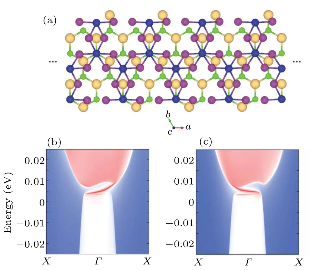
Fig.4. Edge states of CrI3/ScCl2 bilayer. (a)Ribbon cut from the 2D bilayer heterostructure CrI3/ScCl2 along the zigzag direction of the Cr honeycomb lattice. Two edge states of this ribbon are shown in(b)and(c),respectively.
3.4. Effective model to describe the QAHE state of
CrI3/ScCl2heterobilayer
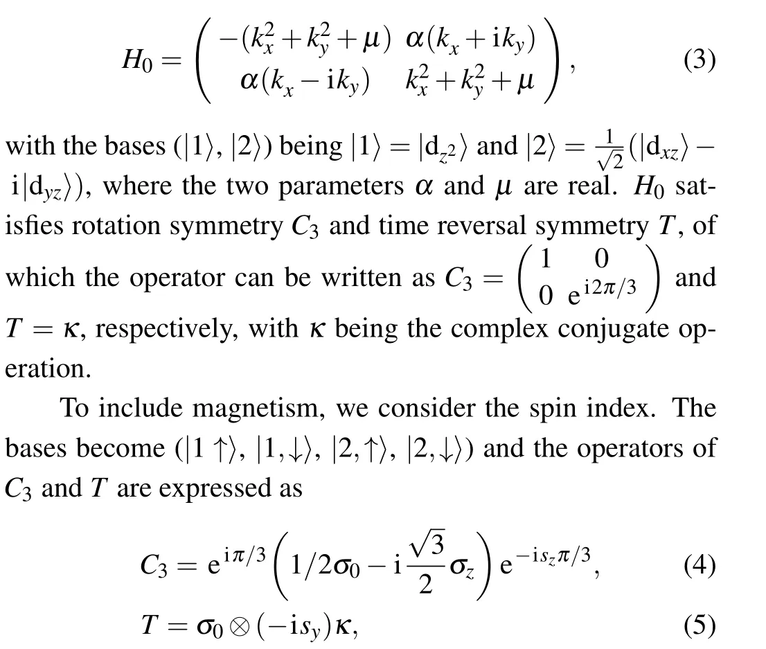
We develop an effective model to reveal the topological origin of the proposed CrI3/ScCl2heterobilayer. According to the first-principles calculation revealed orbital contributions of the two inverted bands,an effective Hamiltonian without considering spin-polarization can be constructed as whereσdenotes the Pauli matrices for orbital andsdenotes the Pauli matrices for spin. The symmetry-allowed SOC Hamiltonian can be found.
As the heterostructure holding interlayer FM interaction,the bases can be chosen as (|1,↑〉,|2,↑〉) and the effective Hamiltonian reminds

without any contribution of the SOC Hamiltonian as the first order approximation,where the parametersαis related to the strength of the splitting at the crossing point of the two inverted bands,while the parameterμindicates the strength of the band inversion. It is suitable to setα2=1 meV and the meaningful range ofμcan be chosen from 5 meV to 2 meV.As shown in Fig.5,for a given value ofα,the band structure can be clearly differentiated into the case with the band inversion forμ <0 and the case without the band inversion forμ >0.
Using the TKNN formula,[43]the eigenvalue, Berry curvature and the CN of the effective Hamiltonian in Eq.(6)can be calculated one by one as


For the case ofμ <0 with the band inversion, CNFM=-1, while for the case ofμ >0 without the band inversion,CNFM=0.

Fig. 5. For the given α satisfied α2 = 1 meV, band structures calculated from the effective Hamiltonian with μ =-5 meV, μ =0 meV and μ =2 meV,respectively.
3.5. External pressure and electric field tuning of the QAHE state of CrI3/ScCl2 bilayer
Since the topological band gap in the CrI3/ScCl2bilayer is the result of the hybridization between the energy bands of the two layers,one possible approach to increase the band gap is to apply an external pressure perpendicular to the 2D plane to reduce the distance between the two layers and to enhance the hybridization of their energy bands.
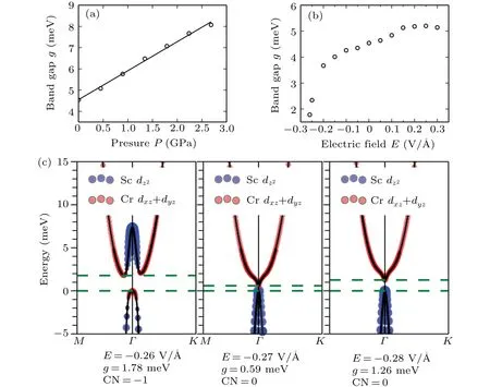
Fig. 6. External pressure and electric field tuning of the QAHE state in CrI3/ScCl2 heterostructure. The result of band gap g is shown as a function of external pressure P(a)or electric field E (b). The positive direction of the electric field is defined from the CrI3 layer to the ScCl2 layer. (c)The elimination of band inversion as well as QAHE from electric field from-0.26 V/?A to-0.28 V/?A.
To test this effect, we perform first-principles calculation for the most stable configuration of the FM-coupled CrI3/ScCl2bilayer at a series of perpendicular compressive pressure while fixing the in-plane lattice constant of the bilayer. The results, as illustrated in Fig. 6(a), indicate that the topological band gap increases linearly as the increase of the pressure and the band gap can be enlarged to 8.1 meV at a pressure of 2.7 GPa with-6% strain along the out-ofplane direction. Calculation shows the out-of-plane FM state is still the magnetic ground state. The out-of-plane AFM state is 14.1 meV higher while the CrI3(out-of-plane)/ScCl2(inplane)state 7.06 meV is higher of one cell.
The application of an external electric field perpendicular to the 2D plane is expected to induce an electric potential difference between the two layers, which would affect the overlapping of the two inverted bands and thus may change the topological nature of the heterostructure. Our first-principles calculation results,as shown in Fig.6(c),indicate that the band inversion can be eliminated as an external electrical field applied along the direction from the ScCl2layer to the CrI3layer larger than 0.27 V/?A and the heterobilayer becomes topological trivial. In addition, upon the application of an external electrical field along the opposite direction, the heterobilayer is still topologically non-trivial and the topological band gap is slightly enlarged,as shown in Fig.6(b).
4. Conclusions
In summary, we have demonstrated, based on firstprinciples calculation, that the QAHE can be robustly realized in the 2D bilayer heterostructure CrI3/ScCl2with a sizable band gap of 4.5 meV and its topological nature and the topologically nontrivial band gap can be effectively tuned by interlayer sliding, the application of a perpendicular external pressure or an electric field. This work provides a new candidate system based on 2D vdW materials for the realization of potential high-temperature QAHE with considerable controllability.
Acknowledgements
We thanks Jiabin Yu and Qingrui Cao for helpful discussion.
Project supported by the National Key Research and Development Program of China (Grant Nos. 2017YFA0204904 and 2019YFA0210004), the National Natural Science Foundation of China (Grant No. 11634011), the Strategic Priority Research Program of Chinese Academy of Sciences (Grant No.XDB30000000),and the Fundamental Research Funds for the Central Universities (Grant No. WK2340000082). Computational support was provided by National Supercomputing Center in Tianjin.
Appendix A
The phonon spectra of ScCl2with out-of-plane and inplane magnetic moments are shown in Fig. A1. The absence of imaginary phonon frequency in both phonon spectra indicates that the ferromagnetic phase of monolayer ScCl2is dynamically stable.

Fig.A1.The phonon spectra of ScCl2 with out-of-plane(a)and in-plane(b)magnetic moments,respectively.
Appendix B
Band structures of monolayer CrI3and monolayer ScCl2with spin orbital coupling are shown in Fig. B1. The band gaps are 0.724 eV (CrI3) and 0.145 eV (ScCl2), respectively.The conduction band minimum(CBM)of CrI3is made by the combination of dxzand dyzorbitals of the Cr atom while the valence band maximum (VBM) of ScCl2is made by dz2orbital of the Sc atom. Both of those two-band extrema locate at the sameΓpoint of the reciprocal space and this makes it possible to generate band inversion and leave a global band gap after the inversion.

Fig. B1. Band structures of monolayer CrI3 (a) and monolayer ScCl2(b),with spin orbital coupling.
Appendix C
As the supercell of ScCl2is a 2×2 unit cell, as shown in Fig. 2(b) in 2×2 periods. Except for stacking (1/6,1/3),whose band structure and distribution of Berry curvature are shown in Figs.3(a)and 3(b),respectively. Here we only give the band structures and the distributions of Berry curvature of stacking (1/3,1/6), stacking (1/2,1/2) with space group ofP3 and CN of-1,and of stacking(1/2,1/6)with space group ofP1 and CN of 0 in Fig. C1. As the band structures do not change so much, the distributions of Berry curvature change significantly.

Fig.C1. (a)and(b)The band structures and the distributions of Berry curvature of stacking (1/3,1/6) and stacking (1/3,1/3) with space group of P3 and CN of -1. (c) The band structures and the distributions of Berry curvature stacking(1/2,1/6)with space group of P1 and CN of 0.
- Chinese Physics B的其它文章
- Design of vertical diamond Schottky barrier diode with junction terminal extension structure by using the n-Ga2O3/p-diamond heterojunction
- Multiple modes of perpendicular magnetization switching scheme in single spin–orbit torque device
- Evolution of the high-field-side radiation belts during the neon seeding plasma discharge in EAST tokamak
- Phase-matched second-harmonic generation in hybrid polymer-LN waveguides
- Circular dichroism spectra of α-lactose molecular measured by terahertz time-domain spectroscopy
- Recombination-induced voltage-dependent photocurrent collection loss in CdTe thin film solar cell

