Study of relationship between motion of mechanisms in gas operated weapon and its shock absorber
Jiri Bll , Romn Vitek , Dung Nguyen Vn , Zynek Krist , Hung Nguyen Vn
a Department of Weapons and Ammunition, University of Defence Brno, Czech Republic
b Department of Weapons, Le Quy Don Technical University, Hanoi, Viet Nam
c Department of Design and Special Engineering, Alexander Dubcek University of Trencin, Slovakia
Keywords:Shock absorber Gas-operated weapon Force-impulse diagram Recoil system Breech block carrier
ABSTRACT The article deals with the motion of the breech block carrier and the weapon casing of an automatic weapon mounted on a flexible carriage and the base of the weapon.Earlier works, which did not consider the dynamic properties of the base of the weapon,did not allow to reconcile the calculated and experimental results of the weapon casing displacement when shooting from firing rests.For the analysis of the motion of individual parts,the methods of mathematical modelling and firing experiments using a high-speed camera were chosen.Calculations show the best accord with experiment when modelling the system with 4 degrees of freedom.The oscillation of the system regarding the movement of the breech block carrier and the weapon casing was investigated under changed conditions of rate of fire,the use of a muzzle brake and different types of shock absorbers.The velocities and displacements of the weapon casing and the breech block carrier at different values of the impulse of the gases to the breech block carrier were determined.
1.Introduction
Most automatic infantry weapons use devices called shock absorbers to reduce the forces load from firing [1].These forces depend on the type of operation, i.e., gas operated, short or long recoil operated or external drive,see Ref.[2].At the same time,such devices improve the conditions of firing stability and ergonomic conditions for the shooter.The 5.56 mm and 7.62 mm machine guns mainly use shock absorbers in variants where they are mounted on bipods, tripods, vehicles, or airplanes and helicopters[3,4].In addition to reducing the already mentioned force load,the weapon must perform movements without shocks,which occur in the extreme positions of the breech mechanism.When firing a burst,there must be no increase in the recoil path due to the close resonance frequencies of the weapon casing and the breech.Moreover,the linear displacement must not exceed the permissible value,which would make it impossible to feed the cartridges in the case of storage of its magazine outside the weapon or when aiming[5-7].This weapon displacement could cause injury to the shooter's eye.
The authors usually study problems associated with the use of shock absorbers that are applied to a specific automatic weapon.The results of the examination depend on the used type of the automatic weapon mechanism drive.The first task is to determine the course of the forces transmitted from the weapon casing to the mount during one or more of functional cycles.The calculation procedures for determining the forces transmitted from the automatic weapon to the mount are shown,for example,in Refs.[1,2,6].Forces analysis begins by determining the forces load on the stiff weapon base, see Ref.[8].All automatic weapons and hand-held weapons are held by a support that is limited in rigidity when firing.Therefore, the actual forces are smaller than those determined by procedures given in Ref.[8],etc.Lu in Ref.[9]presents a very successful method of reducing the recoil force by using a floating weapon mount on a tripod in combination with the initiation of a powder charge with a so-called pre-ignition - advanced primer ignition system (API).The measured forces are much smaller and in the 7.62 mm or 5.56 mm calibre they reach the maximum between 1000 N and 1500 N.Inside the barrel, the maximum force given by the maximum pressure in the barrel can reach up to 14,000 N, as the authors show in Refs.[2,3,8,10,11].
More important than an accurate knowledge of the force of the shot,and its maximum value,is an accurate knowledge of the total force impulse during one functional cycle,see Refs.[1,2,11].This is because most modern mounts for automatic weapons are made to be as light and elastic as possible and so the mount parts have a lower resonance frequency, in the range 8 Hz-300 Hz, which is necessary to know for excluding the resonance states, see Refs.[1,5,12].
The calculation procedures can be considered as the most pessimistic (maximum possible) estimates of the forces transmitted to the mount.As shown in Refs.[3,5,11,12] the most important forces are the force of the shot, forces due to the operation of the mechanisms and their drive.The other forces are the impact forces at the rear and front limited positions and the forces of return springs of the breech and the barrel, see Refs.[1,2,5].
Calculations and technical experiments show the need to consider the effects of flexible properties of the mount on the movement of the automatic weapons parts.
In addition,the complexity of the problem is underlined by the presence of non-linearities such as backlash, dry friction, and almost always using springs with preload,which is another type of non-linearity.
In the case of weapon mechanisms,there are shocks with jump changes in the velocity of movement of hints that do not allow the use of analytical methods used in non-linear oscillations such as a method of harmonious linearization or a small parameter method.It turns out that the most suitable calculation method is direct numerical integration of motion equations and with the possibility of changing(shortening)of the integration step in the course as the use of standard ODE solvers would lead to an unstable solution[4,8,12].
To simplify calculations and when the parameters are unknown,the problem is often simplified to the expression of equivalent stiffnesses, and dry friction is replaced by viscous damping,depending on the relative velocity of movement of the bodies[13-16].
The article presents an extended view of the problem of machine gun mounting with consideration of elastic properties not only of the shock absorber,but also of the elastic properties of the mount and the base of the weapon.In addition, it discusses the effect of rate of fire changes on the behaviour of the system that may occur in use.The problem is solved by a combination of theoretical and experimental procedures.Four bodies are considered: the breech block carrier, the weapon casing, the ballistic carriage, and the basic structure as base of the weapon.The scientific contribution is in the application of the method of analysis of the system with 4 degrees of freedom in combination with the experimental procedure and comparison of the complex solution with simplifications to 3 and 2 degrees of freedom.

Fig.1.System with 2 degrees of freedom (2 DOF).
In this case and regarding the possibilities of technical experiments,a case study on a 7.62 mm gas operated machine gun whose barrel is firmly connected with the weapon casing was chosen.The following Part 2 deals in general with the effect of weapon mount on the weapon casing motion and the mount in terms of the change of natural frequencies of the mechanical system.The third part describes the dynamic models of the motion of an automatic weapon on a mount with a shock absorber and with the weapon base designated as the basic structure.The models with 3 and 4 degrees of freedom and the procedure of experimental verification of the calculations by shooting are described.Part 4 deals with a case study for the motion of the 7.62 mm PKT machine gun,considering firing with and without a shock absorber, with variation of the firing rate of fire within the limits given by the design of the breech block carrier drive,with and without the use of a muzzle brake, and finally the possibility of using other types of shock absorbers than the original two-spring without initial preload was used.
2.Influence of mount on weapon casing motion
According to some authors, such as Refs.[1,2,5,12], the weapon casing movement have neglected effect on the movement of the breech block carrier having low mass at the gas operation automatic weapon.This applies to weapons of 20 mm calibre and above.On the other hand,for small arms up to 12.7 mm calibre,the action and movement of the breech block has a significant effect on the movement of the weapon casing.As a rule, these are externally driving high rate of fire weapons where the decisive force loaded the mount is the force of shot and the movement of the breech blocks does not affect the movement of the entire weapon.The problem of the movement of the weapon casing can be most easily described considering the dynamic properties of the mount, by a model on Fig.1.
The system consists of the mount mass m1, the whole weapon mass m2, the mount stiffness k1, the shock absorber stiffness k2,and corresponding displacements of both masses are x1,x2.The mount is fixed via k1stiffness to the basic structure (stationary firing rest,vehicle chassis,airplane).
The motion equations are
Dissipative properties are not included in the reduced damping coefficients for each degree of freedom.Their determination is difficult, as they depend on dry friction in the guiding of the weapon on the mount and the structural friction and can be determined approximately.When analysing oscillations, it is advisable to first neglect damping, and after determining the natural frequencies, the calculation models can be extended to damped systems as well.

Fig.2.Model represents flexible properties of basic structure with 3 degrees of freedom (3 DOF).

Fig.3.Natural frequencies of 2 DOF system.
For the system parameters m1= 25 kg, m2= 10.5 kg,k1=7×10³N/m,and k2=1×10⁵N/m described by Fig.1 and the equations below,the calculated natural frequencies are f1=2.3 Hz and f2=18.6 Hz.
If we consider the higher value of the mount stiffness k1= 5 × 10⁶N/m according to Refs.[5,12] with the same other values we get the mount frequency shift to 15.1 Hz and of the gun to 19.5 Hz.Natural frequencies are higher.
A dynamic model with 3 DOF also expressing the flexible properties of the basic structure of the weapon is represented by Fig.2.
The system consists of the basic structure mass m1, the mount mass m2,the weapon mass m3.The elastic properties represent the basic structure stiffness k1, the mount stiffness k2, and the shock absorber stiffness k3.The corresponding displacements of all masses are x1,x2,x3.
The motion equations are
The 3 DOF system parameters m1= 650 kg, m2= 25 kg,m3= 10.5 kg, k1= 1 × 10⁶N/m, k2= 7 × 10³N/m, and k3=1×10⁴N/m give the calculated natural frequencies f1=2.2 Hz,f2= 8.5 Hz,and f3=18.6 Hz.
The natural oscillation frequencies of both models are shown in Figs.3 and 4.
The periodic excitation force FEis the force transmitted from the shot and the weapon mechanisms to the weapon casing.It depends on the automatic weapon drive.The basic excitation frequency[Hz]is given by the number of shots per second.The usual course of this force determined from the functional diagram is shown in Fig.5,where is an example of the 7.62 mm machine gun triggered from the rear position.
It means that before every shot the weapon casing begins forward motion and afterwards the force of shot makes the recoil.The gas drive counteracts the weapon casing recoil.The return springs usually do not affect the movement of the weapon,which is due to their low force.The shock force between the breech and the weapon casing in the rear position of the breech causes additional movement to the rear.Finally, after inserting the round into the barrel chamber and impact of the breech in the front position,before the following (here the second) shot, the weapon moves forward.
Publications [1,2,8] give more details.As the works [3,5]mentioned,the short-acting forces,i.e.the force of the shot and the shocks of the breech in the rear and front positions,have a decisive effect on the movement of the weapon.
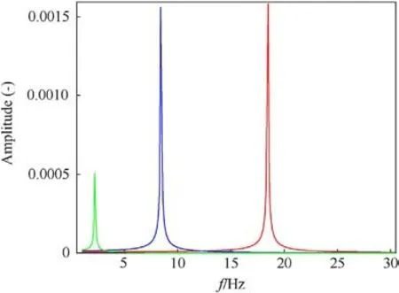
Fig.4.Natural frequencies of 3 DOF system.
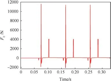
Fig.5.Force diagram of the 7.62 mm gas operated machine gun.
3.Equations of movement of breech block carrier and weapon casing when shooting
3.1.3 DOF dynamic model of weapon mechanism movement and weapon casing when firing
An automatic weapon generally involves multiple mechanisms.The structure of mechanisms is diverse, and complex given the transmission ratios between individual parts.They are usually not constant, but variable over time and over the displacement of movement of the main functional part.In the case examined by us,this member is the breech block carrier.The barrel,which is firmly connected to the weapon casing,does not move.We introduce the following assumptions for the solution.
· Except for springs,which are elastic parts,all the mechanisms in automatic weapons are considered as absolute hard, dynamically linked together, by a variable or constant transmission ratio.
· Rectilinear movement of mechanisms is considered.
· The effects of the clearance between dynamic joints are ignored.
· A 3 DOF system with three concentrated masses according to Alferov [5] in Fig.6 considers: the breech block carrier, the weapon casing and the mount.The mount is fixed to a basic structure.

Fig.6.Model of gas operated weapon with shock absorber and flexible mount [5].
The labels in Fig.6 are:mimass of the ith working mechanisms of automatic weapon, mBBCmass of the breech block carrier, mWmass of the weapon casing, mMmass of the mount, kRS,kA,kMstiffness of the return spring, shock absorber spring and the equivalent spring between mount and basic structure,XBBC,XW,XMcoordinates of the breech block carrier with respect to the weapon casing, the weapon casing, and the mount according to their direction of motion.
The automatic weapon consists of the breech carrier with n mechanisms having miown masses.The transmission ratio and efficiencies from the breech block carrier to the ith working mechanisms i are νiand ηi.
There are many methods to establish the motion equations of automatic weapon mechanism and weapon casing when firing.We use methods of analytical mechanics based on the Lagrange method.
The basis are Lagrange's type II equations [5,16].
where,T,∏are the kinetic and potential energy of the system,qj, ˙qjthe generalized coordinates and velocity, and Qjthe generalized force corresponding to the generalized coordinates, t time, j number of degrees of freedom.We will take the generalized coordinates q1= XBBC, q2=XWand q3= XM.
After determination of the kinetic and potential energy with respect to the transmission functions, the necessary derivations and adjustments,we get the final form of the equations of motion
where,m∑-the mass function of the secondary elements influence with respect to the transmission functions, mη- the reduced mass function of the secondary elements influence with respect to the weapon casing acceleration belonging to the inertial force from the weapon casing,FBBCred-the reduced force acting to the breech block carrier with exception of the return spring force, mν- the reduced mass of the parts belonging to the breech block carrier as the inertial force acting to the weapon casing,mM-the mount mass,FWthe forces acting to the weapon casing including the preload force of the shock absorber, and the passive resistances on the weapon casing.Ref.[5] gives detailed information.
When the weapon with the shock absorber mounted on the absolute hard mount, i.e.XM= ˙XM= XM..= 0, thereafter the motion Eq.(4) are written as
3.2.4 DOF dynamic model
The 4 DOF model including the basic structure movement published in Ref.[14] by Nguyen, and based on the actual placement of the weapon on the STZA12 firing rest is presented in Fig.7.
The motion principle of the model, described in Fig.7 can be described as follows:the result of the forces,acting on the weapon casing during the shot, forces the weapon casing, represented by mass m3, to move along the O2xaxis with respect to the weapon carriage.The connection between the weapon casing and the weapon carriage is flexible, the flexibility of this connection is represented by the spring with stiffness ka.The motion of the weapon casing with respect to the weapon carriage has 1 degree of freedom(DOF).
Subsequently,the breech block carrier,represented by mass m4,starts moving relatively to the weapon casing in the moment when the projectile passes the gas channel in the bore and the weapon automatic mechanism starts working.The connection between the breech block carrier and the weapon casing is flexible due to the usage of the spring with stiffness k0and the motion of breech block carrier with respect to the weapon casing has 1 DOF.
The resulting motion of the weapon casing is transmitted through the shock absorber spring kaon the weapon carriage m2,which is flexibly mounted on the basic structure m1.The flexibility of the connection between the weapon carriage and the basic structure is represented by the spring with stiffness kyand it has 1 DOF.
Finally,the basic structure is connected with the ground and can move with respect to the ground along the O0xaxis.This motion has 1 DOF and the connection between the basic structure and ground is considered as sliding and the motion of the basic structure with respect to the ground is affected mainly by friction forces.Secondary members formed by the mechanisms of an automatic weapon (for example, the feed mechanism) perform movements linked by cam gears depending on the movement of the breech block carrier.They are represented by the mass mi.
The motion equations were derived using the matrix method for determining kinetic energy.The other forces between bodies,including excitation forces were determined by the method of virtual works [14].
In contradiction with Eq.(3) were used Lagrange equations in form
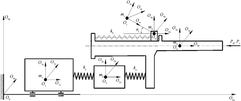
Fig.7.Nguyen dynamic model with 4 DOF [14].
The breech block carrier equation
After arrangement, we obtained the following Eqs.(7a), (7b),(7c), and (7d).
The Firing rest base (as the basic structure) equation
The mount (ballistic carriage) equation
The weapon casing equation

Fig.8.Scheme of motion sensors placement on the firing rest.
The calculation of the motion of the mechanism of the automatic weapon and its weapon casing when firing is done in the process of solving simultaneously the system of differential Eqs.(5)-(7) with the system of differential equations of the thermodynamic equations in the gas chamber, the gas drive according to the displacement x or time t.After solving the system of differential equations, we determine the laws of the breech block carrier, the weapon casing, the mount or the basic structure.
The systems of differential Eqs.(5)-(7) were solved using the Maple software with an integration step of 0.00001 s.The choice was based on earlier calculations, where it was shown that this choice would ensure sufficient accuracy and stability of the calculation.
For the cases of machine gun mounting, it turned out that it is sufficient to consider 3 DOF and only two movements in the case of an inflexible mount.In the case of the carriage of powerful automatic cannons,the need for an another,i.e.at least the 4th degree of freedom,would be necessary,as the results showed,for example,in Refs.[3,8,12].The main reason for this necessity is that the firing power of these weapons affects the motion of the weapon base and these movements are transferred back to the mount(cradle,upper carriage), elevating and traversing mechanisms and the weapon itself.The load of the carriage and basic structure is immense,it is necessary to consider the possibility of basic structure motion with respect the ground.Therefore, in the case of described weapon,where the main moving parts are breech block carrier, weapon casing and weapon carriage(3 DOF at all),the basic structure had to be added as the 4th DOF.
The results of the calculations were confronted with technical experiments carried out on the STZA 12 ballistic rest with the possibility of mounting automatic weapons up to 12.7 mm calibre.
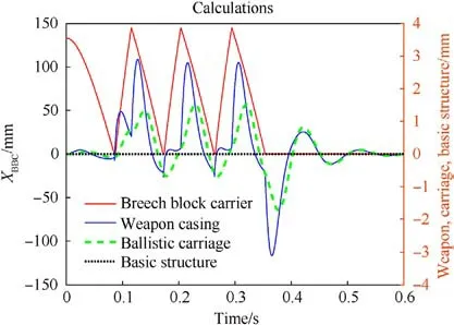
Fig.10.Results of calculations - 3 shots.
The arrangement of sensors and cameras for recording movements are shown in Fig.8 on left.For determination of all parts movement,the contrast circle marks were situated on the specified parts of the weapon,the ballistic carriage,and on the firing rest,see Fig.8 on right.We used high-speed camera with recording speed 10,000 fps.The motion of individual parts of the weapon was determined using the methods of digital image processing and the digital photogrammetry.The single camera photogrammetry method was used in this case, supposing that all parts of the weapon move in the planes parallel to the camera's image plane.The image scale has been determined using the signalized points with known relative positions, connected which each evaluated parts of weapon.The measurement uncertainty of this method was presented in Ref.[17].The cases of shot firing single and three-shot bursts were experimentally investigated in variations with and without a muzzle brake, with the setting of the regulator in three positions.Subsequent processing of the video sequences from the high-speed camera was performed in the manner published in Ref.[4].
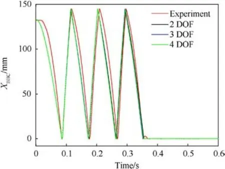
Fig.13.Breech block carrier displacements.
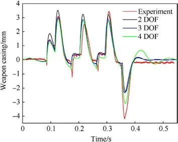
Fig.14.Weapon casing displacements.

Fig.11.Results of experiments - one shot.
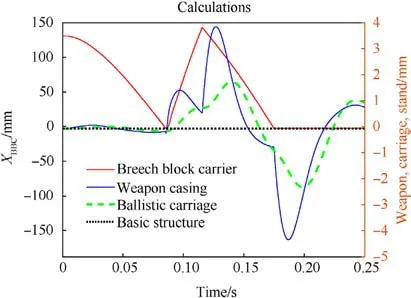
Fig.12.Results of calculations - one shot.
Because the breech block carrier is not visible in case of 7.62 mm PKT machinegun, the motion of this weapon part was evaluated using the steel rod,firmly connected with the breech block carrier.This rod protruded from the rear part of the weapon casing and the reference points were signalized on this rod (see photograph in Fig.8.Scheme of motion sensors placement on the firing rest.).The basic eigen frequency of this rod is relatively high (f>6.5 kHz) and the amplitudes of the longitudinal vibrations of this rod are below the resolution capability of the high-speed camera system.Therefore,the longitudinal motion of this rod has been considered as the longitudinal motion of the breech block carrier.
The ballistic carriage can be attached to the rest with the spring excluded, simulating a rigid weapon mount without the flexible mount corresponding to the 2 DOF system when the basic structure motion is blocked.In Figs.9 and 10 there are measured and calculated data for basic settings of the PKT machine gun.The burst and single shot firing regime were tested.
From Figs.9-12 it is obvious that for 7.62 mm calibre machine guns the movement of their basic structures (here the rest) varies within 1 mm.This leads to the decision of a possible reduction of the number of degrees of freedom to 3 or 2 in the calculations,especially in the case of the powerful weapons as the cannons e.g.,where the load of the carriage and basic structure is immense.It is necessary to consider the possibility of basic structure motion with respect to the ground.Therefore,in the case of described weapon,where the main moving parts are breech block carrier, weapon casing and weapon carriage(3 DOF at all),the basic structure had to be added as the 4th DOF.On the other hand, the 4 DOF model is more suitable for the analysing of the weapon casing displacement together with the breech block carrier,as illustrated by the graphs in Figs.13 and 14.
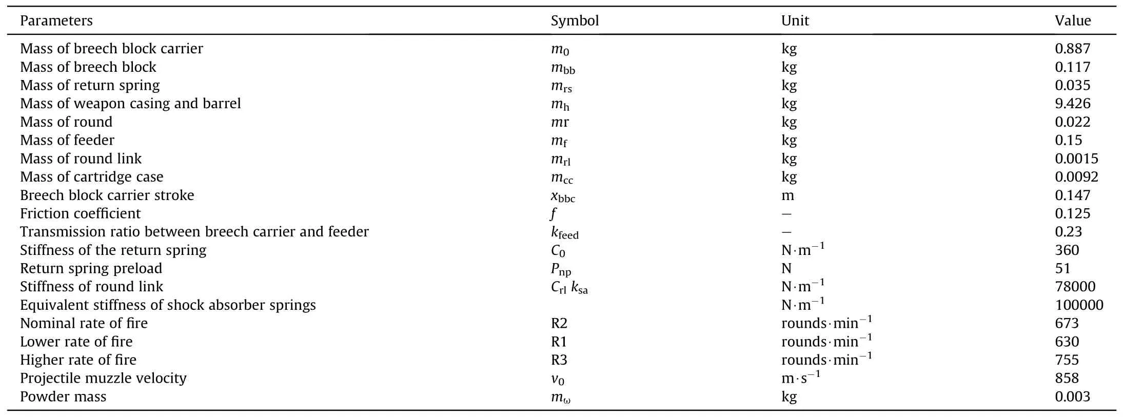
Table 1 Main parameters of system.
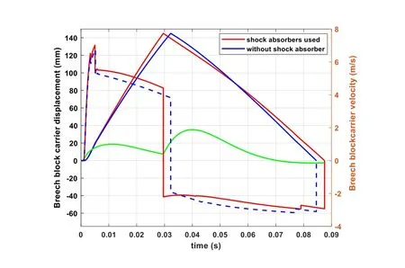
Fig.15.Influence of shock absorber on the displacement and velocity of breech carrier.
This emphasises the consideration of the necessity to investigate not only the movement of the breech carrier and the weapon casing,as reported in Ref.[6],but also the movement of the mount,see Refs.[5,14].The results reported here confirm the necessity of introducing the properties of the mount, and the basic structure,whether it is a stationary base, in this case the firing rest, or for moving bases such as combat vehicles or combat aircrafts, etc.A similar problem has been solved by the author [12] in the case of the analysis of the 100 mm tank cannon operation during recoil,mounted on the heavy firing rest.He recommends including the socalled double recoil effect in the computational model, otherwise an acceptable agreement between calculations and experiments cannot be achieved.Similarly, the problem would be solved when the gun is mounted on a combat vehicle,where the mass itself is a parameter that significantly affects the behaviour of the system.
Comparison of the calculations according to the number of degrees of freedom showed the desirability of introducing additional moving bodies,see Figs.13 and 14 showing the breech carrier and weapon casing displacements.
These results allow computer simulations to address issues related to the operation of the machine gun breech block carrier and the movement of the weapon casing under various firing conditions.
4.Interaction between automatic gas-operated weapon with fixed barrel and its shock absorber
In many cases, the way of mounting of weapon on the basic structure affects significantly not only the motion of individual moving parts of the weapon but also the other important parameters of the combat system - i.e.the rate of fire, the course of the transmitted force on the mount or the basic structure,and the firing stability of the entire combat system.The operation of the main functional element of an automatic weapon is affected by the use or non-use of a recoil damper (shock absorber).The stiffness of the shock absorber influences the natural frequency of oscillation of the weapon casing and this frequency must be outside the range of the firing excitation frequencies (at least the fundamental frequency)determined by the operation of the weapon mechanisms.
To understand these laws, it is necessary to examine simultaneously the operation of the main automatic weapon function element and the recoil damper inserted between the weapon casing and the mount.The following results are presented using a case study of a 7.62 mm PKT machine gun mounted on a firing rest.
The dimensional and mass characteristics were determined by measurements directly on the weapon or obtained from technical documentation.The other input parameters of the system were determined in Refs.[14,15] and due to the large number of inputs only the most important parameters are listed here, see Table 1.

Table 2 Breech block carrier velocities in limit positions without and with shock absorber.

Table 3 Functional cycle time without shock absorber and with shock absorber.
The individual firing rate controller setting positions correspond to excitation frequencies f1=10.3 Hz,f2=10.8 Hz and f3=12.6 Hz.The 7.62 mm PKT MG has the rate of fire of 700 shots/min-800 shots/min, which corresponds to a firing rate of 11.6 Hz-13.3 Hz.The machine gun used in the experiments had fired over 5000 rounds, therefore, lower values of the firing rate were obtained during the experiments than the values corresponding to the new weapon.
4.1.Effect of shock absorber use on breech block carrier motion
To see the effect of shock absorbers on the working of the automatic weapon mechanisms when firing, we conduct research on the operation of the weapon mechanisms with and without a shock absorber.
Fig.15 shows the effects of the shock absorber on the movement of the breech block carrier, where the green line belongs to the weapon casing displacement.The dashed blue line indicates the breech block carrier velocity when the shock absorber is not used.The weapon casing displacement distinguishes two branches.The first is from the shot till the impact of the breech block carrier to its rear position in the weapon casing.The second one is after this impact till the impact of the breech block carrier in the front position.
The calculations were considered for the nominal setting of the rate of fire regulator,affecting the amount of gases taken from the barrel to the breech block carrier piston and therefore its velocity.The breech block carrier velocity after the impact in the rear position influences the next weapon casing movement.The whole weapon tends to move backwards again, as represented by the green curve on Fig.15.The ratio between the velocities before the impact and after the impact of the breech block carrier in the rear position changes the tFCfunctional cycle time.In this case, the movement time of the breech block carrier to the rear position is reduced due to the velocity of the weapon casing in the same rearward direction at the beginning after the shot.As a result of the increase in the breech carrier velocity, the operating time of the shock absorber is reduced,and thus the tFCfunctional cycle time is shortened.Tables 2 and 3 show in detail the velocities and individual times at the main moments of the weapon's operation.The time periods t1and t2are the times of movement of the breech block carrier from the forward position to the rearward position and vice versa.

Fig.16.Displacement of breech carrier and weapon casing with different rate of fireone shot.
The above results can be explained as follows: when using a shock absorber, the initial velocity of the breech block carrier increases due to the additional velocity of the weapon casing when the gas pressure in the barrel begins to act on it, and when the breech block is locked.The increase in the absolute displacement of the breech block carrier is caused by the displacement of the weapon casing.The change in the ratio between the breech block carrier velocities before and after the rear position is caused by a change in the impact conditions.The 7.62 mm PKT machine gun do not have a buffer to reduce the hard impact of the breech block carrier when it reaches its rearward position.Most of 7.62 mm machine guns have some buffers either spring or in combination with a hydraulic brake.In the case of machine guns mounted on combat vehicles, the shock absorber reduces the force effects of firing on the vehicle.
4.2.The effect of changing rate of fire on the weapon operation and the motion of the weapon casing
The change in the amount of gases flowing to the breech block carrier piston is considered when is analysed the effect of weapon mechanism drive on its motion and the weapon casing.In many automatic weapons this is done by means of a so-called regulator,which has two to five positions that change the flow of gases from the barrel to the gas system.In most cases, the amount of gases flowing from the barrel is many times less than the amount of gases acting on the bottom of the projectile and the bottom of the barrel,so that the effect of the removed gases on the pressure course in the barrel is neglected[18,19].The impulse of the force of these gases is critical to the operation of an automatic weapon driven by gases withdrawn from the barrel, since its magnitude determines the maximum velocity of the breech block carrier required to achieve the desired rate of fire.
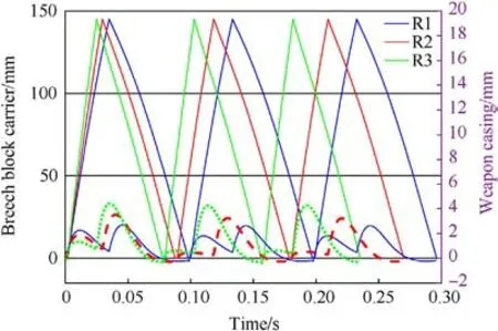
Fig.17.Displacement of breech carrier and weapon casing with different rate of fire.
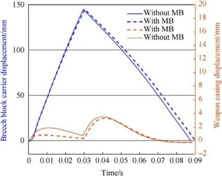
Fig.18.Influence of muzzle brake use - one shot.
The driving force acting on the breech block carrier is determined by the working area of the breech block carrier piston and the gas pressure acting on piston,according to procedures given in Refs.[1,15,18,19]for example.The gas pressure in the gas cylinder is influenced by many factors,such as the gas pressure in the barrel at the moment of gas withdrawal from the barrel and the design parameters of the gas equipment, see Refs.[15,18].
The function of the weapon's automatic and the shock absorber weapon will be tested in two limiting cases.Firstly,with increased and then decreased gas consumption relative to the baseline condition when the rate of fire is given by the controller in position R2.
a) A case of one shot
Fig.16 shows the course of displacement of the breech block carrier (blue curve) and the weapon casing (red curve) with reduced gas consumption (marked R1) and increased gas consumption(marked R3).The vertical axis on the right belongs to the weapon casing displacement, the left vertical axis belongs to the breech block carrier displacement.We get the tFCfunctional cycle time from the timeline.
The differences are visible in the weapon casing displacement graph and functional cycle times.The movement of the weapon casing is divided into two parts.The first corresponds to the movement from the beginning to the impact of the breech block carrier in the rear position,and the second one corresponds to the movement from this point to the impact of the breech block carrier in the front position.In all cases,the trajectory of the weapon casing is greater after the second impulse caused by the impact of the entire breech in the rear position.The resulting initial impulse on the gun case at the time of firing is smaller.

Fig.19.Influence of muzzle brake use - three-round burst.

Table 4 Functional cycle time without shock absorber and with shock absorber.
There is an obvious explanation for this phenomenon,that with a smaller intake of gases from the barrel to the breech, the initial impulse on the weapon casing is reduced less and thus this impulse is greater.On the other hand,with a greater impulse of gases at the breech, the initial impulse on the weapon casing is more reduced,i.e.the initial displacement is smaller,but due to the higher velocity of the breech, when there is a greater impact of the breech in the rear position,the displacement after this impact is higher,as shown the red dashed curve on the graph in Fig.16.
· For the case of lower gas consumption (R1) and lower rate of fire: tFC= 0.098 s, the maximum value of the displacement of the weapon casing in the first part is xmax=2.2 mm,and in the second one is xmax= 2.6 mm.
· When larger consumption (R3) and higher rate of fire:tFC= 0.078 s, the maximum value of the displacement of the weapon casing in the first section is xmax= 1.3 mm, and in the second one is xmax= 4.4 mm.
The result is a greater displacement of the weapon casing in the case R3 than in the case R1, but the tFCoperating cycle time is shorter by 20 ms.
b) A case of three-shot firing
According to the calculation, see Figs.3 and 4, it turns out that with the original shock absorber without preload,the PKT machine gun has a natural frequency over 18 Hz, which allows the movement of the weapon outside the values of maximum excited frequencies between 10 Hz and 13 Hz given by settings of the gas intake regulator.The weapon reacts significantly to three impulses:the impact of the breech block carrier in the forward position and almost simultaneously the moment of firing and the drive from the gases from the barrel and the impact of the breech block carrier in the rear position.These three significant impulses are repeated periodically according to the given rate of fire of the weapon.The system is excited in the sub resonant area and is able to observe changes in excitation force at different settings of the rate of fire controller, see Fig.17 when the machine gun fires three-round burst.

Fig.20.Displacement of the breech carrier and the weapon casing with different shock absorber- one shot.

Fig.21.Displacement of breech carrier and weapon casing with different shock absorber - three-round burst.
4.3.Influence of muzzle brake use
The effect of the muzzle brake(MB)changes the initial impulse of force from the shot.When using a muzzle brake, the initial impulse of the force of shot will be smaller, which will result in a smaller shift of the weapon casing and without the muzzle brake the shift will be greater.
Fig.18 shows the effect of the muzzle brake with 44%efficiency on the movements of the breech block carrier and the weapon casing during a single shot, and Fig.19 during a three-shot burst.Both charts confirm this assumption.It is obvious that the usage of the muzzle break significantly reduces the backward velocity of the weapon casing during the beginning phase of the shot(during the first shot in the burst, respectively).Therefore, the load of the weapon carriage is decreased.
The effect of the muzzle brake is important for the movement of the weapon, but the working cycle time is almost unchanged, as evidenced by various design solutions of the PKT machine gun using not only the muzzle brake but also the flash hider, for example in combat vehicles.
4.4.Influence of shock absorber spring characteristics on weapon casing motion
This part deals with the influence of the shock absorber type on the movement of the weapon casing.Shock absorbers with the FA0initial preload will be considered.Refs.[6,7,13] provide a method for the design of different types of the one spring shock absorber.The tAcycle time of the weapon casing,i.e.the time of the weapon casing recoil and the counter recoil,is compared with the tFCcycle time of the breech block carrier, or with the t1time, see Table 3.
Based on this condition,the following types of shock absorbers are used:
half-cycle, when tA= t1.
single-cycle, when tA= 0.8t1,
two-cycle, when tA= tFC,or multiple cycle(floating)shock absorbers,when tR=ntFC.The n number of shots,n ≥2.
Results of the calculated parameters of the new shock absorbers used for the 7.62 mm PKT machine gun are given in Table 4.
The parameter fNis the natural frequency of the weapon casing oscillation on the shock absorber,the kAis the stiffness of the shock absorber spring.
Results of the 7.62 mm PKT machine-gun displacement study with different types of the shock absorbers according to Table 4 are shown in the following Figs.20 and 21, Tables 5 and 6.
The displacement law of the multi-cycle shock absorber breech block carrier and the weapon casing is greatly different from that of the half-cycle,single-cycle and twin-cycle.The natural frequency of the weapon casing displacement is lower than the frequency of rate of fire.It is the reason for this weapon casing behaviour on the mount.
It has been shown that with the 7.62 mm calibre machine gun,when used,the weapon casing starts to move before the first shot is fired.This is due to the motion of the breech block carrier to the forward position,where the force of the return spring acting to the rear(in the direction of the weapon recoil)overcomes the force of the shock absorber and frictional forces.This has not been demonstrated experimentally for a two-spring shock absorber without preload used before.

Table 5 Functional cycle time and maximum stroke of the weapon casing with different shock absorbers types.

Table 6 Breech block carrier velocity in critical positions with different shock absorbers types when firing burst.
Only in the case of a half-cycle shock absorber,the movement of the weapon during subsequent shots starts from the basic position.It is considered according to the weapon position at the moment of the first shot.In the case of a single-cycle, double-cycle, or multicycle (floating) shock absorber, the weapon is always moved in the recoil direction.
The use of multi-cycle shock absorbers may be recommended in the case of mounting high rate of fire automatic weapons and for automatic weapons, where there is a requirement for a minimum force transmitted to the mount even at the cost of extending the weapon recoil displacement, see Refs.[20,21].These are more powerful weapons on bases of 12.7 mm calibre and higher,including weapons of the OCSW (Objective Crew Served Weapon)type.In this case,the excitation frequency given by the rate of fire is high and the use of other shock absorbers would result in high necessary forces that would have to return the gun to the base position in a short time.In addition, with the time between shots from 10 ms to 33 ms, corresponding to rates of fire from 6000 rounds/min to 1800 rounds/min,the shock absorber would have to be equipped with springs of high stiffness[1,6,11,14].
Automatic weapons with external drives, such as Chain Guns[1,22], Gatling Guns [23-26] have rate of fire proportional to the drive engine angular velocity, due to the inertial properties of the drive.Only after the start in a few tenths of a second has a weapon of nominal rate of fire.This deficiency will cause lower number of shots during the shooting from 0.05 s to 1 s and affects the hit probability of moving targets.After the system acceleration in a few tenths of a second the weapon fires with a nominal rate of fire.The Gatling gun studied in Ref.[25] achieves the nominal rate of fire within 200 ms after acceleration using the permanent magnet electric motor.
Especially for aircraft cannons, it is necessary to keep the maximum permissible force transmitted to the gun mount.The lowest achievable force per gun mount in the case of a flexible mount is 2-3 times greater than the mean force transmitted to the gun carriage during the time between two shots,see Refs.[11,16].It is determined by knowing the frequency characteristic of the weapon and comparing the excitation frequency and the natural frequency of the weapon.
5.Conclusions
The simulation model of automatic weapon with 2, 3 and 4 degrees of freedom (DOF) has been designed.The mounted 7.62 mm PKT machine gun has been adopted as the real object for the purpose of this work.The best accord with experimental data has the model with 4 DOF having the breech block carrier,weapon casing, weapon mount and the static basic structure.The shock absorber was modelled by the stiffness and damping of the connection between the weapon casing and the weapon mount.
The calculated course of motion of the ballistic carriage shows the necessity of introducing non-linearity of the stop type in the given specific case, since the movement of the gun carriage (here represented by the ballistic carriage)is limited in the basic position by the stop on the shooting rest.
Comparing the numerically and experimentally obtained data it has been approved that the behaviour of the automatic weapon mechanisms is mainly affected by the parameters of the automatic drive with minor influence of the parameters of the shock absorber.On the other hand, the load of the weapon mount and the basic structure are significantly affected by the shock absorber parameters as well as by the automatic drive parameters.This information can be utilized in design practice for e.g.the estimation and evaluation of the rate of the fire, the operational reliability, the firing stability, and the other important technical and tactical properties of automatic weapon system.
Even though the presented mathematical model and experiments are applied to the 7.62 mm PKT machine gun on a shock absorber, the published conclusions and procedures of the theoretical and experimental analysis are also applicable to other automatic weapons mounted on combat vehicles, aircrafts, and vessels.
Declaration of competing interest
The authors declare that they have no known competing financial interests or personal relationships that could have appeared to influence the work reported in this paper.
Acknowledgements
The work presented in this paper has been supported by the Research project VAROPS(Military autonomous and robotic assets)of the Ministry of Defence of The Czech Republic, and by the Specific Research Support Project(Grant No.SV22-201)financed from funds of the Ministry of Education, Youth and Sports of The Czech Republic.
- Defence Technology的其它文章
- Explosion resistance performance of reinforced concrete box girder coated with polyurea: Model test and numerical simulation
- An improved initial rotor position estimation method using highfrequency pulsating voltage injection for PMSM
- Target acquisition performance in the presence of JPEG image compression
- Data-driven modeling on anisotropic mechanical behavior of brain tissue with internal pressure
- The effect of reactive plasticizer on viscoelastic and mechanical properties of solid rocket propellants based on different types of HTPB resin
- Tuning microstructures of TC4 ELI to improve explosion resistance

