Numerical Research on The Nozzle Damping Effect by A Wave Attenuation Method
Wan-xing SU,Ning-fei WANG,Jun-wei LI*,Yan-dong ZHAO,Mi YAN
Numerical Research on The Nozzle Damping Effect by A Wave Attenuation Method
Wan-xing SU,Ning-fei WANG,Jun-wei LI*,Yan-dong ZHAO,Mi YAN
School of Aerospace Engineering,Beijing Institute of Technology,Beijing 100081,China
Nozzle damping is one of the most important factors in the suppression of combustion instability in solid rocket motors.For an engineering solid rocket motor that experiences combustion instability at the end of burning,a wave attenuation method is proposed to assess the nozzle damping characteristics numerically.In this method,a periodic pressure oscillation signal which frequency equals to the f i rst acoustic mode is superimposed on a steady f l ow at the head end of the chamber.When the pressure oscillation is turned off,the decay rate of the pressure can be used to determine the nozzle attenuation constant.The damping characteristics of three other nozzle geometries are numerically studied with this method under the same operating condition.The results show that the convex nozzle provides more damping than the conical nozzle which in turn provides more damping than the concave nozzle.All the three nozzles have better damping effect than that of basic nozzle geometry.At last, the phase difference in the chamber is analyzed,and the numerical pressure distribution satisf i es well with theoretical distribution.
Copyright?2013,China Ordnance Society.Production and hosting by Elsevier B.V.All rights reserved.
Solid rocket motor;Combustion instability;Wave attenuation method;Nozzle damping
1.Introduction
Solid rocket motors are often prone to combustion instability that is characterized by the periodic pressure oscillations in the chamber[1].Such oscillations can result in severe thrust oscillations and rocket structure vibrations[2].Combustion instability in solid rocket motors has been a continuing problem since the f i rst rockets were used in World War II[3]. Over the past few decades,a considerable amount of time and money has been spent on suppressing combustion instability in solid rocket motors.The‘rules of thumb’methods include inserting a slab into the hole of the tubular grain,drilling a series of radial holes in the grain[4],changing the geometry of the grain,especially at the head end of the motor,adding aluminum or other inert particles into the propellant[5],and modifying the nozzle geometry[6]and so on.Although the combustion instability can be suppressed to some extent,the low frequency axial combustion instability is a thorny issue that needs to be considered in the design of large solid rocket motors till now.
In recent years,the fundamental acoustic instability has been occurred in several rocket motors at the end of burning, as shown in Fig.1.This low amplitude but sustained pressure oscillation greatly affects the performance of the motor.The low axial combustion instability cannot be suppressed by using metal powders or metallic oxide particles.In contrast, the particles can increase the pressure oscillation by interacting with the parietal vortex shedding[7].As for a structure fi xed solid rocket motor,the increase in nozzle damping effect is a most effective way to suppress the combustion instability because the nozzle damping is one of the principal damping mechanisms.The nozzle damping accounts for about 50%ofthe total damping effect,small changes in aft geometry and nozzle type can lead to big changes in motor stability.The acoustic pressure waves can be transmitted through the nozzle throat and radiated to the environment.The theoretical determination of the nozzle damping is a diff i cult gas dynamical problem.Crocco and Sirignano[8]did a fundamental investigation on the treatment of nozzle admittance.He considered that the motion of wave in the nozzle is three dimensional and the mean f l ow is one dimensional.Janardan and Zinn[9,10] experimentally studied the damping of axial instabilities of small scale nozzles under cold-f l ow condition.They concluded that the conical nozzle provides more damping than the equalradii-of curvature nozzle.Anthoine et al.[11]numerically studied the effect of nozzle cavity on solid rocket motor with a submerged nozzle.He concluded that the evolution of the maximum sound pressure level is approximately linear with the nozzle cavity volume.Therefore,in order to increase the nozzle damping,the nozzle geometry should be fully considered at the beginning of motor design.
In this paper,a wave attenuation method is provided numerically to assess the nozzle damping characteristics based on an engineering solid rocket motor that experiences combustion instabilityattheendofburning.Thenumericalworkiscarriedout onthreeotherdifferenttypicalnozzlegeometries(convexnozzle, conicalnozzle,andconcavenozzle).Boththepressureoscillation characteristics and the damping effects are obtained.The numericalresultscanbeforreferenceinthedesignandmodif i cation of solid rocket motor to improve the stability.
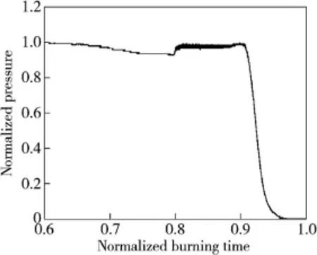
Fig.1.Example of combustion instability.
2.Wave-attenuation method
Up to date,the nozzle damping characteristics have been measured using several methods,such as frequency-response method,standing-wave method and wave-attenuation method [12].In this paper,the wave-attenuation method[13]is utilized and is implemented in a numerical way.A periodic pressure oscillation which frequency equals to the f i rst acoustic mode is superimposed on a steady f l ow at the head end of the chamber.When the pressure oscillation signal is turned off,the decay rate of the pressure can be used to determine the nozzle damping effect.It is supposed that there is no other source of acoustic energy exists in the chamber, and the acoustic energy consumption of energy due to viscosity is ignored.Therefore,the acoustic energy is not affected by other factors than the nozzle itself.The time history of the pressure can be expressed as follows after turning off the pressure oscillation

The RNG k-ε turbulence model is included to close the N-S equations.The second-order implicit formulation is used in an unsteady solver.A Courant-Friedrich-Lewy (CFL)number of 1 is imposed,and a time step is 5×10⁻⁵s.
The simplif i ed 2-D axisymmetric model of the engineering solid rocket motor that experiences combustion instability at theendofburningisshowninFig.2.Thewholecomputational domain contains nearly 240,000 cells with the mesh ref i ned near the wall and the mass f l ow inlet.The smallest grid spacing at the propellant surface is about 1 mm. The boundary condition is also illustrated in Fig.2.For the purpose of keeping the actual working conditions,a constant mass f l ow inlet is chosen to simulate the burning of propellant. Without the consideration of combustion kinetics,the thermodynamic properties are assumed as the constants for the present study.The temperature at the inlet is kept at 3500 K. The f l ow variables at the exit are extrapolated from the f l ow variables within the computational domain.
In order to employ the wave-attenuation method in the numerical work,a periodic pressure oscillation signal which frequency equals to the f i rst acoustic mode(-177 Hz)is superimposed on a steady f l ow at the head end of the chamber via UDF(user def i ned function)for 0-0.3 s,and then the pressure oscillation is turned off to determine the decay rate of the pressure.Five virtual pressure monitors are set along the mass f l ow inlet to record the pressure changing history.The detailed locations of monitors are listed in Table 1.
Three other different typical nozzle geometries(convex nozzle,conical nozzle,and concave nozzle)are used in the numerical work to compare with the basic design nozzle.The four nozzles are shown in Fig.3.The operating conditions of the four cases are the same so as to facilitate comparison.The pressure oscillation characteristics,nozzle decaying coeff i cient and pressure phase distribution are analyzed in the following section.
4.Results and discussion
4.1.Pressure oscillation characteristics
The simulation f i rstly carries out about 2000 steady iterations with a good convergence of the solution.Then the periodic pressure oscillation is added at the head of the chamber to simulate a combustion instability phenomenon,and the unsteady simulation is restarted for a physical time of 1 s.The pressure oscillation is turned on for 0-0.3 s,and then is turned off.The variations of the pressure at 5 virtual monitors are saved.Fig.4(a)is a typical example that shows the pressure oscillation characteristics when the pressure oscillation is on. The pressure spectrum after FFT(fast Fourier transform)of the pressure signal is shown in Fig.4(b).It is apparent that the oscillation is dominated by the f i rst axial acoustic mode.
Both pressure oscillation characteristics at the head(Point 1)and the end(Point 5)are calculated in the same way.For comparison,Case 0(basic design)is set as a reference.The pressure amplitudes of all cases are divided by the amplitude of Case 0.Accordingly,the relative pressure amplitude of Case 0 is 1.The relative pressure amplitude under different nozzle geometries is shown in Fig.5.It clearly shows that the convex nozzle has the lowest relative pressure amplitude of 0.91 at Point 1,and the relative pressure amplitudes of conical nozzle and concave nozzle are 0.93 and 0.96,respectively. Both the head and end signals have the same tendency.
In Anthoine’s research work[11],he concluded that the evolution of the maximum acoustic pressure level is approximately linear with the nozzle cavity volume.In fact,the volume of aft end cavity is indeed increased from Case 3 to Case 0,as shown in Fig.3.Thus,the relative pressure amplitude is gradually increased in the previous order. Blomshield[3]emphasized that the nozzle damping is decreased if there is an abundant burning area in the aft end. Generally speaking,the acoustic energy attenuation effect of the convex nozzle is greater than that of a concave nozzle[6]. Furthermore,Zhao and Kang[14]experimentally concluded that the acoustic scattering effect of the convex nozzle is better than that of conical nozzle.The present result conf i rms the above-mentioned conclusions.

Fig.2.Computational model and boundary conditions.

Table 1Monitor coordinate.

Fig.3.Different nozzle geometries.
4.2.Nozzle decay coeff i cient
The periodic pressure oscillation is turned off at 0.3 s after it is turned on.The data of Monitor 1 is utilized in this section. The pressure decaying process is demonstrated in Fig.6. According to Eq.(1),the amplitude of the pressure oscillation decays in an exponential way.Therefore,the attenuation constant after pressure oscillation off can be obtained by plottingthepeak-to-peakamplitude-timecurveina logarithmic-time coordinate system,as shown in Fig.7.
The scattered points can be linear f i tted in a line,and the slope of the line is the attenuation constant according to Eq. (2).The slope in Fig.7 is the attenuation constant αNof Case 0.The comprehensive comparison of the attenuation constants of the four different nozzle geometries is shown in Fig.8. From Case 0 to Case 3,the attenuation constants are -10.7 s-1,-11.03 s-1,-11.06 s-1and-11.13 s-1,separately.The conclusion drawn in Section 3.2 is the same with that in Section 3.1.The damping effect of the convex nozzle is better than that of conical nozzle,which in turn is better than that of concave nozzle.The basic nozzle has the worst damping effect because of aft end cavity bigger than the other three geometries.Generally,the damping effect of the non-submerged nozzle is better than that of submerged nozzle.The basic nozzle(Case 0)is a typical submerged nozzle while the others are no-submerged nozzle.Fig.8 clearly shows the above conclusion.
The pressure oscillation characteristics and nozzle decay coeff i cients for the different nozzle geometries show the same conclusion.It conf i rms that the numerical method is reasonable and effective.Though the calculated nozzle attenuation constants are signif i cantly smaller than the actual ones,the numerical method provides an easier and cheaper way to evaluate the nozzle damping effect before the design of a new solid rocket motor.

Fig.4.Pressure oscillation characteristics at Point 1 of Case 0.
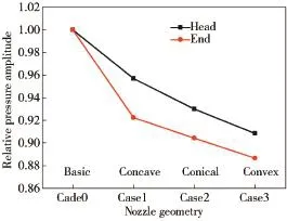
Fig.5.Relative pressure amplitude under different nozzle geometries.

Fig.6.Pressure decaying process after pressure oscillation off.
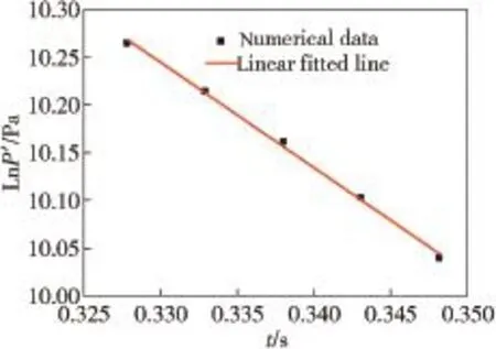
Fig.7.Ln(P')-t curve after pressure oscillation off.
4.3.Pressure phase distribution
The acoustic pressure distribution along the chamber length is also concerned in the research on combustion instability. The rocket chamber is closed at the forward end.On the opposite,the sound at the nozzle throat can prevent the acoustic perturbations from propagating through it.Therefore, the chamber can be simplif i ed as a closed-closed tube from an acoustical point of view.And the acoustics is presented in the form of standing wave.Ideally,the two ends of chamber are the pressure anti-nodes of f i rst acoustic pressure,where the pressure oscillation can reach to maximum but has a phase difference of 180°.Monitor 1(head)and Monitor 5(end)of Case 0 are taken for example.The phase difference is illustrated in Fig.9.In one pressure oscillation period of T,the f i rst pressure peak of Point 1 is ahead of T/2 compared with Point 5.It indicates that the pressure signals of Point 1 and Point 5 have an opposite phase.The intermediate position(Point 3)of the nozzle is the pressure node where the pressure oscillation is zero.Theoretical and numerical f i rst acoustic distributionsare plotted on a double Y-axis in Fig.10.It can be shown from Fig.10 that the numerical distribution satisf i es with theoretical distribution.Both Point 1 and Point 5 have the maximum amplitude because they locate at the pressure anti-node,while Point 3 nearly has no oscillation.The amplitudes of Point 2 and Point 4 are between the maximum and minimum.
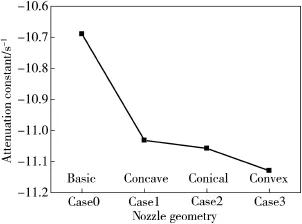
Fig.8.Attenuation constants of different nozzle geometries.
From an engineering point of view,it is more effective to modify the grain structure at the place of pressure antinodes. However,the grain design should not have an abundance of burning area in the aft end,because the nozzle damping may be decreased according to the present numerical results.Zhang et al.[15]summarized that a head end cavity can effectively suppressthe pressure oscillation.Inorder toreducethepressure oscillation to a maximal extent,both the grain modif i cation and nozzle geometry optimization should be comprehensively considered before the design of new large solid rocket motors.
5.Conclusions
(1)A wave attenuation method was provided numerically to calculate the nozzle attenuation constant.It is an easier and cheaper way to evaluate the nozzle damping effect.
(2)Both the relative pressure amplitude and nozzle attenuation constant verify that the convex nozzle provides more damping than the conical nozzle,which in turn provides moredampingthantheconcavenozzle.Allthethreenozzles have better damping effect than the basic nozzle geometry.
(3)Pressure phase distribution analysis shows that the numerical pressure distribution satisf i es well with theoretical distribution.The pressure oscillations at the head end of the chamber are equal and are 180°out of phase from those in the aft end of the chamber.
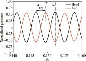
Fig.9.Phase difference between pressure sensor 0#and 4#.

Fig.10.Theoretical and numerical acoustic pressure distributions.
[1]Sun WS.Combustion instabilities in solid rocket motors.Beijing:Beijing Institute of Technology Press;1987[in Chinese].
[2]Zhang Q,Wei ZJ,Su WX,Li JW,Wang NF.Theoretical modeling and numerical study for thrust-oscillation characteristics in solid rocket motors.J Propuls Power 2012;28(2):312-22.
[3]Blomshield FS.Lessons learned in solid rocket combustion instability. AIAA;2007.p.5803.
[4]Xie WM.Solid rocket motor combustion instability,aerospace engineering textbook.Xi’an:Northwestern Polytechnical University Press; 1984[in Chinese].
[5]Blomshield FS,Stalnaker RA,Beckstead MW.Combustion instability additive investigation.AIAA;1999.p.2226.
[6]Hu DN,He GQ,Liu PJ.Study on instable combustion of solid rocket motor with f i nocyl grain.J China Ordnance 2011;7(1):24-8[in Chinese].
[7]Guery JF,Ballereau S,Godfroy F,Gallier S,Orlandi O,Pieta PD,et al. Thrust oscillations in solid rocket motors.AIAA;2008.p.4979.
[8]Crocco L,Sirignano WA.Behavior of supercritical nozzles under threedimensional oscillatory conditions.AGARD-OGRAPH-117;1967.
[9]Janardan BA,Daniel BR,Zinn BT.Scaling of rocket nozzle admittances. AIAA J 1975;13(7):918-23.
[10]Zinn BT.Nozzle damping in solid rocket instabilities.AIAA J 1973;11(11):1492-7.
[11]Anthoine J,Buchlin JM,Guery JF.Effect of nozzle cavity on resonance in large SRM:numerical simulations.J Propuls Power 2003;19(3):374-84.
[12]Janardan BA,Zinn BT.Rocket nozzle damping characteristics measured using different experimental techniques.AIAA J 1977;15(3):442-4.
[13]Buffum RG,Dehority GL,Slates RO,Price EW.Acoustic attenuation experimentsonsubscalecold-f l owrocketmotors.AIAAJ 1967;5(2):272-80.
[14]Zhao BH,Kang SZ.Design of solid propellant rocket engine aiming at a damping of the mid-frequency instability.J Beijing Inst Technol 1982;02:76-86[in Chinese].
[15]Zhang Q,Li JW,Su WX,Zhang Y,Wang NF.Studies on effect of head cavity on resonance damping characteristics in solid rocket motors. AIAA;2012.p.3729.
10 July 2013;revised 21 August 2013;accepted 25 August 2013 Available online 3 October 2013
*Corresponding author.
E-mail address:david78lee@gmail.com(J.W.LI).
Peer review under responsibility of China Ordnance Society
Production and hosting by Elsevier
2214-9147/$-see front matter Copyright?2013,China Ordnance Society.Production and hosting by Elsevier B.V.All rights reserved.
http://dx.doi.org/10.1016/j.dt.2013.09.016
- Defence Technology的其它文章
- The Research on Compressive Properties of Polytetraf l uoroethylene at High Strain Rate
- First-principles Study of Electronic Structures,Elastic Properties and Thermodynamics of the Binary Intermetallics in Mg-Zn-Re-Zr Alloy
- Design Method of Equipment Optimization Development Based on Standardization Theory
- The Spatial Color Mixing Model of Digital Camouf l age Pattern
- Research on Optical Properties and Micro-processing Characteristics of Collodion Thin Film
- Application of Space-time Conservation Element and Solution Element Method in Intake and Exhaust Flows of High Power Density Diesel Engine

