Spacecraft attitude maneuver control using two parallel mounted 3-DOF spherical actuators
Li Guidn,Li Hike,Li Bin
aSchool of Electrical and Information Engineering,Tianjin University,Tianjin 300072,China
bState Grid Tianjin Power Dongli Power Supply Branch,Tianjin 300300,China
Spacecraft attitude maneuver control using two parallel mounted 3-DOF spherical actuators
Li Guidana,*,Li Haikeb,Li Bina
aSchool of Electrical and Information Engineering,Tianjin University,Tianjin 300072,China
bState Grid Tianjin Power Dongli Power Supply Branch,Tianjin 300300,China
Attitude maneuver;Backstepping control;Null motion;Parallel configuration;Singularity;Spherical actuator
A parallel configuration using two 3-degree-of-freedom(3-DOF)spherical electromagnetic momentum exchange actuators is investigated for large angle spacecraft attitude maneuvers.First,the full dynamic equations of motion for the spacecraft system are derived by the Newton-Euler method.To facilitate computation,virtual gimbal coordinate frames are established.Second,a nonlinear control law in terms of quaternions is developed via backstepping method.The proposed control law compensates the coupling torques arising from the spacecraft rotation,and is robust against the external disturbances.Then,the singularity problem is analyzed.To avoid singularities,a modified weighed Moore-Pseudo inverse velocity steering law based on null motion is proposed.The weighted matrices are carefully designed to switch the actuators and redistribute the control torques.The null motion is used to reorient the rotor away from the tilt angle saturation state.Finally,numerical simulations of rest-to-rest maneuvers are performed to validate the effectiveness of the proposed method.
1.Introduction
Control moment gyros(CMGs)are widely used in spacecraft attitude control,which is attributed to the advantages of high torque capacity and no propellants.1–3Especially,the single gimbal CMG(SGCMG)features the torque amplification capability.However,complex gimbal structures,large servo parts and commonly required cluster configurations limit their applications to small spacecraft.In contrast,multi-degree-offreedom(multi-DOF)spherical electromagnetic momentum exchange actuator(SEMEA)has great advantages of reducing attitude control system(ACS)mass,volume and power requirements because of their higher structural integration.4Furthermore,its largest asset is that a single device is capable of generating three-axis control torques because the variablespeed rotor can be tilted in any direction,which shows great prospect in 3-axis spacecraft attitude control.5,6
Over the past decades,a variety of structural forms of spherical actuators have been proposed,which commonly have a spherical rotor or a spherical stator.Downer et al.7proposeda magnetic rotor suspension system including a magnetic annulus rotor and a spherical stator.An armature is used to induce rotation of the rotor and the spin axis can be gimbaled by selectively exciting the control coils on the stator.A similar ball joint type magnetic bearing for tilting body can be found in Ref.8.Note that if the armature is moved outside the stator,it will allow a larger tilting range,increasing the amount of angular momentum exchangeable between the actuator and the spacecraft.Based on this idea for structural improvements,Che′telat et al.9put forward a reaction sphere actuator with an 8-pole permanent magnet spherical rotor and a 20-pole electromagnet stator.The rotor can be electronically accelerated in any direction,and it is by magnetic levitation that the rotor is held in position.Instead of a multipole magnet,Chabot et al.10,11proposed a design using a spherical dipole magnet as the rotor,which is inexpensive and readily available.Similarly,in Ref.12,we proposed a new type of spherical momentum exchange device based on a permanent magnet spherical motors(PMSM)13and the detailed design consideration is presented in Ref.14.Compared with multi-axis magnetic momentum wheels,15its spherical-profile and dihedral-shell PMs can maintain the uniformity of the air–gap magnetic flux density when the rotor is in motion,and can help acquire a larger tilting range.From the perspective view,a single spherical actuator can be an alternative to conventional CMG clusters.However,its rotor tilt range is limited and the singularity occurs when the rotor tilt angle is saturated.Therefore,the control law and steering logic need to be concerned with the singularity.To overcome this drawback,ann-step incremental rotation strategy16was introduced in Ref.12.In fact,the steering strategy belongs to an open-loop scheme,which is sensitive to the unexpected external disturbances,spacecraft parameters and initial attitude errors.In general,more practicable singularity avoidance schemes and robust feedback control laws are desired.
In this paper,we focus on the attitude maneuver control using spherical actuators.In CMG systems,cluster configuration17and path planning18are effective singularity avoidance strategies.When the system falls into the singularity state,null motion can be used to reconfigure the CMGs to preferred gimbal angles.Referring to this method,a parallel configuration for SEMEAs is investigated to avoid the tilt angle saturation singularity and simultaneously to provide redundancy.The dynamic equations of motion are derived by the Newton-Euler approach.Noting that the control system has a cascaded structure,we adopt a backstepping control law.19,20When the tilt angle saturation singularity is encountered,a modified weighed pseudo inverse steering law based on null motion is applied,and the weighted matrices are carefully designed.To validate the effectiveness of the proposed method,numerical simulations of rest-to-rest maneuvers are carried out.
2.Introduction to SEMEA
The prototype and schematic of the SEMEA are presented in Fig.1.The SEMEA is mainly composed of an electromagnetic stator and a PM rotor.The universal mechanical shaft in the PMSM is cut off only for momentum exchange purpose.Its variable-speed rotating rotor can be tilted in any direction,thus realizing three-dimensional momentum exchange with the spacecraft platform.
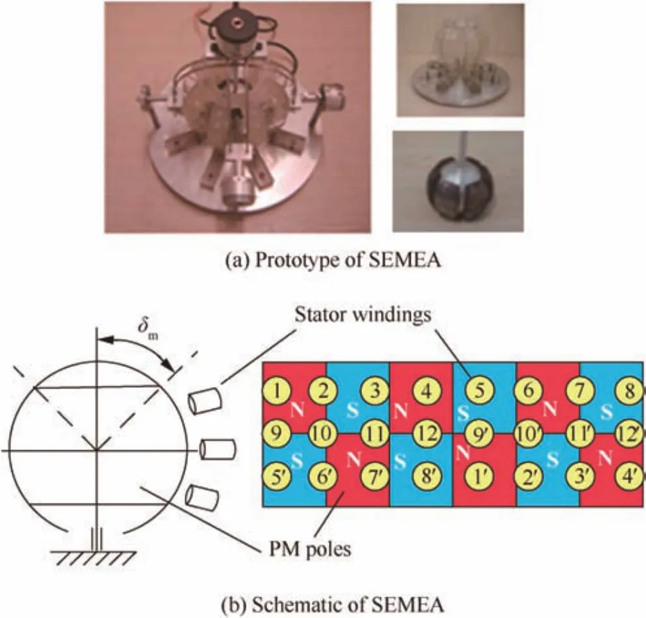
Fig.1 Illustration of SEMEA.
The actuator works on the electromagnetic torque T,whose characteristics are determined by stator currents I,and the arrangements of stator windings and rotor permanent magnets(Fig.1(b)).The relationship can be expressed as T=KTI where KTis the defined static torque characteristic matrix.Thus,the rotation and tilt of the rotor can be controlled by the stator currents I.Related control laws and electrifying strategies can be found in Refs.21,22.For simplicity,ideal rotor trajectory tracking is assumed in this paper.Note that the mechanical structure and the air–gap magnetic field distribution limit the rotor tilting range(the maximum of the rotor tilt angle δm=15°).
3.Analytical model of spacecraft with two SEMEAs
In this section,the Newton-Euler method is employed to derive the complete dynamic equations of motion for a spacecraft with two parallel mounted SEMEAs.The attitude kinematics is described in terms of quaternions.
3.1.Dynamics equations of motion
To simplify the development,we first consider a rigid spacecraft with only one SEMEA.Afterwards,we extend the result to the complete system.As shown in Fig.2(a),the stator housing and the spacecraft body are treated as one platform.A reference frameBwith basis(b1,b2,b3)is fixed with the platform.The center of mass of the overall systemOis taken as the origin of coordinates.The spacecraft platform is free to translate and rotate with respect to the inertial frameN,with i1,i2and i3the unit vectors.The origin of coordinates is at the rotor’s center of massORand rRis the distance vector fromOtoOR.
To facilitate computation,a rotor’s outer virtual gimbal frameGwith orthogonal unit vectors(g1,g2,g3)and inner virtual gimbal frameHwith orthogonal unit vectors(h1,h2,h3)are established to define the orientation of the rotor in the spacecraft platform(Fig.2(b)).The unit vectors g2,h1and h3are parallel to the outer virtual gimbal axis,inner virtual gimbal axis and spin axis,respectively.The frameBtransforms to the framesGandHby Euler angle rotations through the outer virtual gimbal angel and inner virtual gimbal angel,respectively.The spherical rotor rotates around the spin axis at speed rate Ω.When the initial gimbal angles are zero,the unit vectors(h1,g2,h3)coincide with the unit vectors(b1,b2,b3)of frameB.The unit vector g2stays fixed relative to the frameB,and any unit vector gior hican be obtained by the following direction cosine matrices:

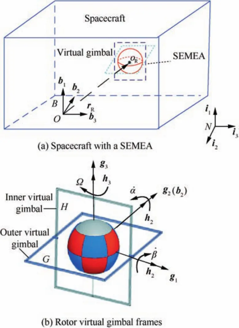
Fig.2 Models for derivation of equations of motion.
where α and β are outer and inner virtual gimbal angles,respectively.In the vector expressions,the subscripts indicate the relative motion.The absolute angular momentum HRof the rotor with respect to its center of massORis given by

where ωRstands for the absolute angular velocity of the rotor;ωrhis the relative angular velocity of the rotor with respect to frameH,ωhgthe relative angular velocity of frameHwith respect to frameG,ωgbthe relative angular velocity of frameGwith respect to frameB,and ω the absolute angular velocity of the spacecraft platform;IRis the rotor inertia matrix.LetIhbe the moment of inertia of the rotor about its spin axis.Assume that the spherical rotor is completely symmetrical,and then in any frame IRis a constant diagonal matrix

According to the definition of the rotor virtual gimbal coordinate frames,

Since there is no angular momentum for the virtual gimbals,the total angular momentum of the overall system with respect to its center of massOis given by

where HBis the absolute angular momentum of the spacecraft platform,andmRthe rotor mass;E is unit matrix;rRis the modulus of rR.Let Ibbe the inertia matrix of the platform with respect toO,and then H is rewritten as

Let Lerepresent the external disturbance torques experienced by the system.According to Euler’s equation,the initial time derivative of H is given by


Substitute Eqs.(4)and(5)into Eq.(9),and the dynamic equation of motion of the system is obtained as follows:

where IS=IB+IRis a constant matrix.The right of Eq.(11)represents the output torques produced by the actuator.The first term represents the torque caused by the motion of the spacecraft body,the second term represents the torque caused by the rotor accelerations,and the third term represents the torque caused by the rotor tilt rate or rotation acceleration.
From here on,we extend the result to the case of the spacecraft with two SEMEAs.Then the dynamics equation of motion of the overall system can be obtained from Eqs.(9)and(11)in the following form:
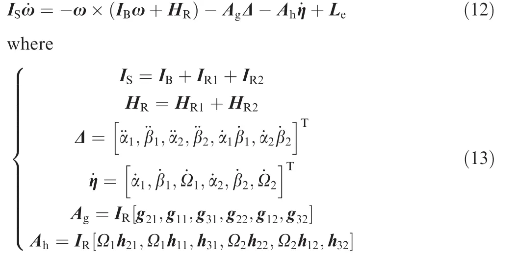
with the subscripts 1 and 2 indicating the two SEMEAs.
3.2.Attitude kinematics
In this paper,the quaternion q=[q1,q2,q3,q4]Tis used to describe the attitude of the spacecraft and the desired attitude is adopted as the inertial frame,i.e.,the command quaternion qc=[0,0,0,1]T.In this case,the kinematic differential equation in terms of error quaternion is expressed as follows23:

where qeV=[qe1,qe2,qe3]Tandqe4are the vector and scalar parts of the error quaternion qe,respectively,ω=[ω1,ω2,ω3]T;and[q×eV]is the slew-symmetric matrix defined by

4.Nonlinear backstepping control law design
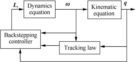
Note that the attitude control system described by Eqs.(12)and(14)has a cascade structure,and the effective backstepping method can be used to develop the feedback law.The control block diagram is presented in Fig.3.
It is assumed that the current state of the system α,β,Ω,ω and q can be measured in real time.We first consider the subsystem described by Eq.(14).To bring the spacecraft to the desired final attitude,the tracking law ωf=[ωf1,ωf2,ωf3]Tcan be considered as pseudo control input.The error state variables e1and e2are defined as

LetVabe the following Lyapunov candidate function:

The time derivative ofVais obtained as

To makeVa≤0,we select the linear tracking function19as follows:

wherekiare positive constants.
After ωfis determined,the real command input should be determined to guarantee the pseudo-control input to be achieved.We define the following Lyapunov candidate function for the overall system:

The time derivative ofVcan be written as follows:

Substituting Eqs.(12),(16)and(20)into Eq.(22)gives


where Lrand Lostand for the required torque and the output control torque,respectively;ρ andlMare positive constants.The external disturbance torques are bounded by

Substituting Eqs.(20)and(24)into Eq.(23)gives

Accordingly,the backstepping control law guarantees the asymptotically stability of the closed-loop system according to the Lyapunov theory.
5.Singularity avoidance steering law design
As shown in Eq.(13),Agdoes not contain Ω and thus is much smaller compared to Ah,and it is usually dropped.The steering law constraint given in Eq.(24)is then simplified as

Each column vector of Ahrepresents the output control torques produced by the rotor tilt motion or spin acceleration,corresponding to CMG mode and RW mode,respectively.Note that the inner virtual gimbal angle β never equals 90°(δm=15°)and rank(Ah)≡ 3.This is to say,within the tilting range,the output torque of a single SEMEA spans the entire space.However,when the rotor tilts to the bound,there exists a direction in which an output torque cannot be generated.It is perpendicular to the spin axis and points outwards.This direction is called the ‘tilt angle saturation singularity direction”.When the required torque lies in this direction,a single SEMEA cannot avoid the singularity because there is no null space to reorient the rotor.In contrast,for a parallel configuration with two SEMEAs,a modified null motion strategy can be resorted to in order to avoid this singularity.
For Ahis never rank deficient,naturally,the standard Moore–Penrose inverse can be used to obtain a minimum norm solution for˙η,and then the resulting simplified velocity steering law is given by

Note that it is not applicable in practice if the solution tends to exceed the restricted range but the rotor has reached up to the bound.It is eagerly anticipated that the tilt angle will decrease automatically at the next time.However,the ideal case is infrequent and the tilt angle saturation singularity is more likely to happen.To avoid the singularity,when one of the actuators falls into the saturation state,the other one should switch to provide effective control torques,meanwhile,the saturated rotor should be reoriented to a preferred position away from tilt angle saturation.A modified weighted pseudo inverse steering logic based on null motion can be implemented

where E6represents a 6×6 identity matrix;W1and W2are weighted matrices used to switch the actuators and redistribute the control torques.They are defined to be

wherewiare positive scalars which control how heavily the SEMEAs are to perform in reaction wheel mode or CMG mode.24For simplicity,herewiare all set to 1.The parameters μ1and μ2are switch weights.Let δ1and δ2represent the two rotors’tilt angle respectively,then μ1and μ2are functions of δ1and δ2.They are defined to be

where δmirepresents the maximum of the two rotors’tilt angle,and μ-ithe value of μiat the last moment.And Nd is the SEMEA null motion.Let constant vector ηfbe the desired rotor position,and the vector d is selected as

wherekeis a positive gain to be appropriately chosen,and W3a diagonal matrix associated with rotor’s reorienting movement given by

As shown in Eq.(31), μ1and μ2are either 0 or 1.If μ1is 1,this means that the resulting steering law will be performed with rotor 1 to be reoriented to the desired position and at the same time rotor 2 providing effective control torques onto the spacecraft.As we can see,AhNd=0,i.e.,the SEMEA null motion produces no torques onto the spacecraft.The stability of null motion has been demonstrated in Ref.25.
6.Numerical simulations
According to the dynamics model,nonlinear control laws and steering laws have been discussed,and numerical simulations of rest-to-rest maneuvers are performed for two main objectives:(1)to confirm the asymptotically stability of the backstepping feedback law;(2)to demonstrate the effectiveness of the proposed singularity avoidance steering logic for the parallel configuration.The external disturbance torques are selected as

Two cases with different tilting ranges are considered in our simulations.The detailed simulation parameters are listed in Table 1.In Case 1,the maximum tilt angles are just as normal(δm1= δm2=15°).During the maneuvers,it may not encounter the tilt angle saturation.In order to demonstrate the working principle of the steering law clearly,a singularity case is needed.Therefore,in Case 2,the maximum tilt angle of rotor 1 is modified(δm1=8°,δm2=15°)to ensure that the singularity will happen.The simulation results are presented in Figs.4–6.Note that the two cases share the same responses of thespacecraft platform,but different SEMEA responses.The rotor tilt angle response illustrates the working process of the steering law clearly.
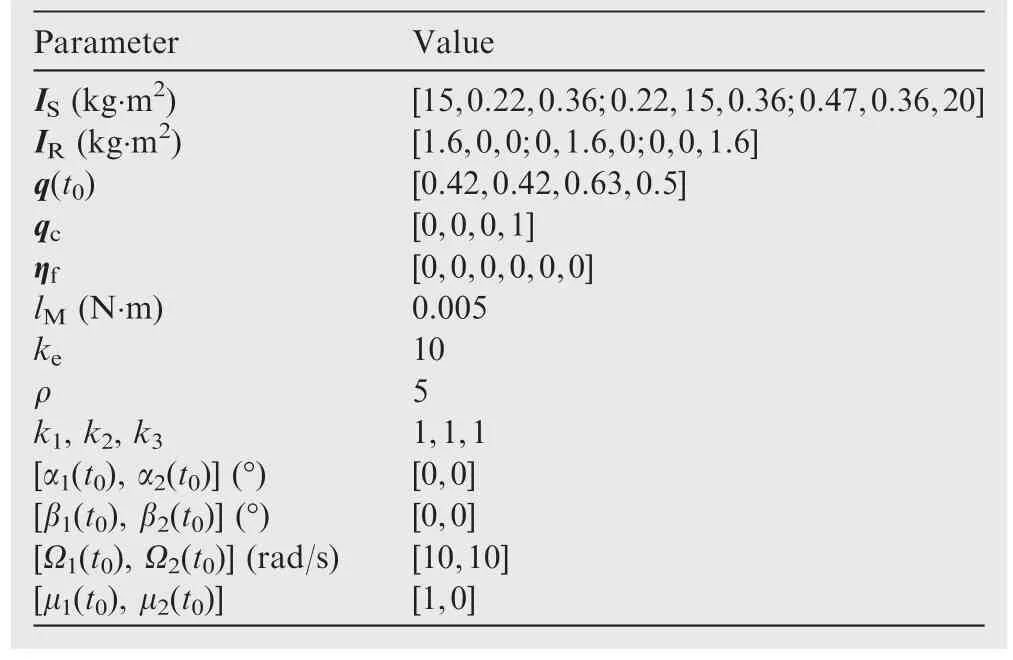
Table 1 Simulation parameters.
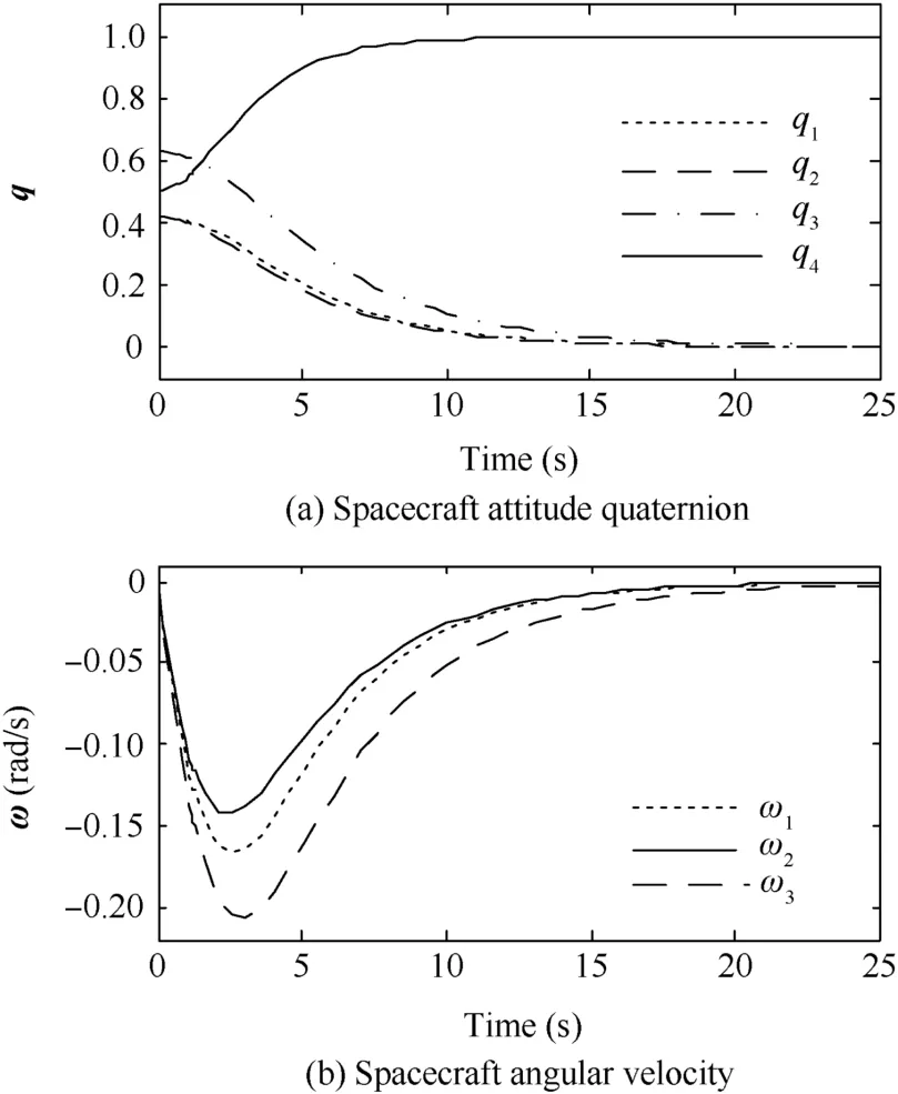
Fig.4 History responses of spacecraft.
Fig.4 shows the history responses of the spacecraft.Fig.4(a)plots the responses of the attitude quaternion,and Fig.4(b)gives the body angular velocity responses.From the simulation results,it can be seen that the proposed nonlinear control law is asymptotically stable and performs very well.The large angle attitude maneuver is effectively achieved with the existence of the external disturbance torques.

Fig.5 History responses of SEMEAs for Case 1(δm1= δm2=15°).
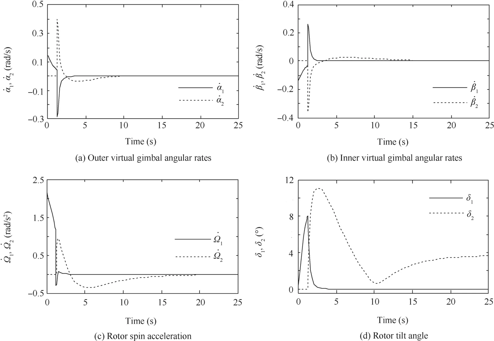
Fig.6 History responses of SEMEAs for Case 2(δm1=8°,δm2=15°).
As shown in Fig.5,in Case 1,it does not encounter the singularity.The maximum tilt angle of rotor 1 approximately equals 9.7°(around 2.6 s),and it is within the tilting range.During the maneuver,therefore,only SEMEA 1 works and provides control torques while SEMEA 2 holds the initial states.It is apparent that the tilt saturation may happen if the maneuver mission is changed or the tilting range is decreased,just as in Case 2.
As shown in Fig.6,in Case 2,at the beginning of the maneuver SEMEA 1 first provides control torques,and around 1.2 s it tilts to the maximum.At this moment,SEMEA 2 switches to produce effective torques onto the spacecraft,meanwhile,null motion drives SEMEA 1 away from the saturation state.Around 5 s,it is brought to the initial position.Thus,the tilt angle saturation singularity is successfully avoided.The drawback of the weighting matrices is that the tilt angular rates of the rotor change extremely sharply at the switch point,which requires the actuator to make a very fast dynamic response in practice.
7.Conclusions
(1)The full equations of motion of a rigid spacecraft with two spherical actuators mounted in parallel are derived.Compared with conventional CMG system,the spherical actuator’s gimbal-less structure makes the formula more accurate and simple.
(2)A nonlinear control law based on the backstepping control method is developed with the external disturbance overcome.To avoid singularity,a modified version of weighted velocity steering law based on null motion is proposed and the weighted matrices are carefully designed.
(3)The simulation results validate the effectiveness of the
proposed control law and the singularity avoidance steering law.Ideal rotor trajectory tracking for the actuator is assumed in the simulation.In practice,fast dynamic response of the SEMEA is crucially required.Device optimization and preferred configuration need
to be studied in the future work.
Acknowledgements
This study was co-supported by the National Natural Science Foundation of China(No.51677130)and the Independent Innovation Funds of Tianjin University(No.1405).
1.Hu Q,Zhang JR.Attitude control and vibration suppression for flexible spacecraft using control moment gyroscopes.J Aerosp Eng2015;29(1):04015027-1–04015027-12.
2.Hu Q,Jia YH,Xu SJ.Adaptive suppression of linear structural vibration using control moment gyroscopes.J Guid Control Dyn2014;37(3):990–6.
3.Zhang JR.Steering laws analysis of SGCMGs based on singular value decomposition theory.Appl Math Mech2008;29(8):1013–21.
4.Fausz J,Wilson B,Hall C,Richie D,Lappas V.Survey of technology developments in flywheel attitude control and energy storage systems.J Guid Control Dyn2009;32(2):354–65.
5.Zhang L,Chen W,Liu J,Wu X,Chen IM.Accuracy enhancement of the spherical actuator with a two-level geometric calibration method.Chin J Aeronaut2014;27(2):328–37.
6.Gerlach B,Ehinger M,Raue HK,Seiler R.Digital controller for a gimballing magnetic bearing reaction wheel.In:Proceedings of AIAA guidance,navigation,and control conference and exhibit;2005 Aug 15–18.San Francisco.Reston:AIAA;2005.p.1–6.
7.Downer JR,Eisenhaure DB,Hockney RL,Johnson BG.Magnetic bearing and suspension system.United States patent US 4961352;1990 Oct 9.
8.Chassoulier D,Chillet C,Delamare J,Yonnet JP.Ball joint type magnetic bearing for tilting body.United States patent US 6351049;2002 Feb.26.
9.Rossini L,Che′telat O,Onillon E,Perriard Y.Force and torque analytical models of a reaction sphere actuator based on spherical harmonicrotationand decomposition.IEEE/ASMETrans Mechatron2013;18(3):1006–18.
10.Chabot J,Schaub H.Spherical magnetic dipole actuator for spacecraftattitude control.JGuidControlDyn2016;39(4):911–5.
11.Chabot J.A spherical magnetic dipole actuator for space craft attitude control[dissertation].Colorado:University of Colorado;2015.
12.Li B,Yu R,Li H,Li G,Wu T.Modeling and analysis of a 3-DOF spherical momentum exchange actuator for spacecraft attitude maneuver.J Aerosp Eng2015;28(6):04015008.
13.Li GD,Cao JC,Li B,Li HF.Control of permanent magnetic spherical motor based on torque-sharing strategy.Adv Mater Res2013;694–697:1512–8.
14.Li B,Yu R,Li H,Li G.Design considerations of a permanent magnetic spherical motor using spherical harmonics.IEEE Trans Magn2014;50(8):1–9.
15.Gerlach B,Ehinger M,Raue HK,Seiler R.Gimballing magnetic bearing reaction wheel with digital controller.In:Proceedings of the 11th European space mechanisms and tribology symposium;2005 Sep 21–23;Lucerne,Switzerland.Noordwijk:ESA Publication Division;2005.
16.Lappas V,Steyn W,Underwood C.Torque amplification of control moment gyros.Electron Lett2002;38(15):837–9.
17.Kurokawa H.A geometric study of single gimbal control moment gyros.Rep Mech Eng Lab1998;175:135–8.
18.Paradiso JA.Global steering of single gimballed control moment gyroscopes using a directed search.J Guid Control Dyn1992;15(5):1236–44.
19.Kim KS,Kim Y.Robust backstepping control for slew maneuver using nonlinear tracking function.IEEE Trans Control Syst Technol2003;11(6):822–9.
20.Zhang H,Fang J.Robust backstepping control for agile satellite using double-gimbal variable-speed control moment gyroscope.J Guid Control Dyn2013;36(5):1356–63.
21.Wang W,Wang J,Jewell G,Howe D.Design and control of a novel spherical permanent magnet actuator with three degrees of freedom.IEEE/ASME Trans Mechatron2003;8(4):457–68.
22.Guo C.A spherical planning based electrifying strategy of permanent magnet spherical motor.ApplMechMater2015;741:629–45.
23.Wie B,Weiss H,Arapostathis A.Quarternion feedback regulator for spacecraft eigenaxis rotations.J Guid Control Dyn1989;12(3):375–80.
24.Schaub H,Vadali SR,Junkins JL.Feedback control law for variable speed control moment gyros.J Astronaut Sci1998;46(3):307–28.
25.Vadali S,Walker S,Oh HS.Preferred gimbal angles for single gimbal control moment gyros.J Guid Control Dyn1990;13(6):1090–5.
14 January 2016;revised 4 May 2016;accepted 31 October 2016
Available online 21 December 2016
?2016 Chinese Society of Aeronautics and Astronautics.Production and hosting by Elsevier Ltd.This is anopenaccessarticleundertheCCBY-NC-NDlicense(http://creativecommons.org/licenses/by-nc-nd/4.0/).
*Corresponding author.
E-mail address:lgdtju@tju.edu.cn(G.Li).
Peer review under responsibility of Editorial Committee of CJA.
 CHINESE JOURNAL OF AERONAUTICS2017年1期
- CHINESE JOURNAL OF AERONAUTICS的其它文章
- Anti-plane problem of four edge cracks emanating from a square hole in piezoelectric solids
- Stress analysis and damage evolution in individual plies of notched composite laminates subjected to in-plane loads
- Drilling load modeling and validation based on the filling rate of auger flute in planetary sampling
- An adaptive attitude algorithm based on a current statistical model for maneuvering acceleration
- Angular velocity determination of spinning solar sails using only a sun sensor
- Automatic landing system using neural networks and radio-technical subsystems
