Drilling load modeling and validation based on the filling rate of auger flute in planetary sampling
Quan Qiquan,Tang Junyue,Yuan Fengpei,Jiang Shengyuan,Deng Zongquan
State Key Laboratory of Robotics and System,Harbin Institute of Technology,Harbin 150080,China
Drilling load modeling and validation based on the filling rate of auger flute in planetary sampling
Quan Qiquan*,Tang Junyue,Yuan Fengpei,Jiang Shengyuan*,Deng Zongquan
State Key Laboratory of Robotics and System,Harbin Institute of Technology,Harbin 150080,China
Coring;Drilling load;Filling rate of auger flute;Lunar regolith simulant;Planetary drilling
Some type of penetration into a subsurface is required in planetary sampling.Drilling and coring,due to its efficient penetrating and cuttings removal characteristics,has been widely applied in previous sampling missions.Given the complicated mechanical properties of a planetary regolith,suitable drilling parameters should be matched with different drilling formations properly.Otherwise,drilling faults caused by overloads could easily happen.Hence,it is necessary to establish a drilling load model,which is able to reveal the relationships among drilling loads,an auger’s structural parameters,soil’s mechanical properties,and relevant drilling parameters.A concept for the filling rate of auger flute(FRAF)is proposed to describe drilling conditions.If the FRAF index under one group of drilling parameters is less than 1,this means that the auger flute currently removes cuttings smoothly.Otherwise,the auger will be choked with compressed cuttings.In drilling operations,the drilling loads on the auger mainly come from the conveyance action,while the drilling loads on the drill bit primarily come from the cutting action.Experiments in one typical lunar regolith simulant indicate that the estimated drilling loads based on the FRAF coincide with the test results quite well.Based on this drilling load model,drilling parameters have been optimized.
1.Introduction
As the Earth’s closest nature satellite,the Moon completely records the 4.5 billion years evolutionary history of the solar system.Hence,when human beings started extraterrestrial explorations,the Moon definitely was the preferred target.1,2The main goal of lunar exploration is to understand the geological evolution of early stars through analyzing the subsurface composition beneath the surface.Compared with other sampling methods,drilling and coring,due to its efficient penetrating and cuttings removal characteristics,has been widely applied to past planetary sampling missions.3,4
At present,China is performing a lunar exploration program,namely the Chang’E project,the third phrase of which will use a hollow drill with a coring mechanism to capture the lunar soil and bring it back to the Earth.5,6According to reports on the lunar regolith,the lunar surface is largelycovered by a layer of lunar regolith material.The vertical extension of this regolith layer is estimated to be of the order of several meters.7Because mechanical properties of the lunar regolith on different sampling spots or even at different depths on one spot can be quite different,the loads on a drilling device necessary to achieve penetration may often be unpredictable and this fact could seriously affect the stability of drilling.In terrestrial drilling,many types of detecting instruments are commonly used to accurately acquire geological information in order to assist real-time drilling.However,due to the mass and power constraints,such additional instrumentation can often not be implemented in planetary missions.For example,the lunar penetrating radar(LPR)that will be applied on the Chang’E missions,is not accurate enough to obtain the geological information on the lunar surface and near the subsurface that would be required for a safe drilling action.8Therefore,to reduce potential risks in penetrating,drilling loads should be monitored online and be reasonably restricted.
In a piercing process,cuttings in the annular region between the coring tube and the auger’s outer surface are exerted by the cutting action by the cutting blade and are removed in the upward direction by the action,which is generated from the spiral auger and the borehole.9In the cutting and conveyance process described above,the sampling drill suffers reaction forces,generating drilling loads.Research on granular soil’s spiral conveyance indicated that the cuttings’removal action affected drilling loads directly.10When a drill tool has penetrated to a certain depth,the driving power used for the cutting action becomes stable at some level,while the driving power needed for the conveying action increases dramatically and becomes the main power consumer11.
To prepare for future Mars exploration,the University of California,Berkeley conducted a large number of experiments in sandstone cuttings under Martian conditions,revealing that an ice sublimation phenomenon generated by heating could effectively alleviate an auger’s choking,greatly reducing the penetrating velocity and the drilling power.12,13According to the requirements of Chinese lunar exploration missions,the Harbin Institute of Technology analyzed the effects on the coring rate and the rotary torque by a drill tool’s mechanical structure parameters and optimized the structural parameters.14,15It can be obviously concluded that to a specific sampling drill tool,suitable drilling parameters may efficiently reduce uncertain drilling loads.
Due to the restricted hardware resources on a planetary probe,drilling parameters should be reasonably optimized to reduce the drilling power needed for penetration.Establishing a drilling load model and revealing the relationships between the drilling load and the regolith’s mechanical properties,will contribute to optimizing drilling parameters.The failure mode and conveyance state of the lunar regolith under a drill tool’s action are theoretically analyzed in this paper.By using the FRAF index to describe the cuttings removal states of the lunar regolith,a drilling load model containing two typical drilling conditions has been established.Experiments in one typical lunar regolith simulant indicate that this drilling load model based on the FRAF coincides well with test results and can be used to optimize drilling parameters.Optimization indices of drilling parameters are analyzed according to the requirements of future lunar exploration.Based on the validated drilling load model,drilling parameters are optimized for application in lunar regolith simulants.
The remainder of this paper is organized as follows.One typical lunar regolith simulant and one potential drill tool are prepared firstly.The filling rate of the auger flute index is employed to describe the drilling conditions for different drilling parameters.The drilling load model established based on the FRAF index is validated for one typical lunar regolith simulant afterward.Finally,drilling parameters are optimized based on this drilling load model.
2.Lunar regolith simulant and drill tool
In many drilling applications,in particular in natural environments such as planetary surfaces,whose structure and layering are not known in advance,drilling loads have highly unpredictable and non-linear characteristics.Before establishing a drilling load model,a large number of drilling experimentsshould be carried outfirst foracquiring useful drilling state signals,which can serve as a sound basis for modeling.Both the structural parameters of the auger and the mechanical properties of the lunar regolith are expected to have considerable influences on the drilling performance.Therefore,in order to find an optimized set of drilling parameters suitable for application on a planetary lander mission,these influence factors need to be studied and evaluated in advance.
2.1.Lunar regolith simulant
Lunar regolith is a general term for the layer or mantle of fragmental rock material,formed by frequent meteoritic impacts on the atmosphere.16Studies of the returned samples indicate that the lunar regolith mainly contains five basic compositions:rock debris,mineral fragments,breccia,agglutinate,and glass-bonded aggregates.7,17The relative proportions of each composition,depending on the mineralogy of source rocks,vary from place to place,and even at different depths on one spot,they may be quite different.In order to verify our drilling load model,the lunar regolith simulant should mimic the mechanical properties of the real lunar regolith as close as possible.
In this paper,HIT-LS1#soil as shown in Fig.1(a)has been chosen as the sampling material.The main component of HIT-LS1#soil is brown volcanic ash originating from the Jilin Province,China.6After the pressing process,the particle size distribution of this simulant varies from 1 μm to 100 μm,which is similar to that of the returned samples from the Apollo 17 landing site.18The density of HIT-LS1#soil is about 1.878 g/cm3.According to the research by Heiken,among all mechanical properties,the shear strength of the lunar regolith,such as cohesion and internal angle,affects the drilling loads directly.7As shown in Fig.1(b),under a repeated triaxial shear test,the shear strength of HIT-LS1#soil is acquired as follows: the average cohesionc=45.9 kPa and the average internalfriction angle φ =48°.In this paper,the authors just consider the drilling interaction in a homogeneous lunar regolith.To acquire a homogeneous lunar regolith simulant for experimental validation,the lunar regolith simulant was compressed deliberately,which may resultin a high cohesion.19,20.The drilling experiments will be conducted based on this typical lunar regolith simulant.
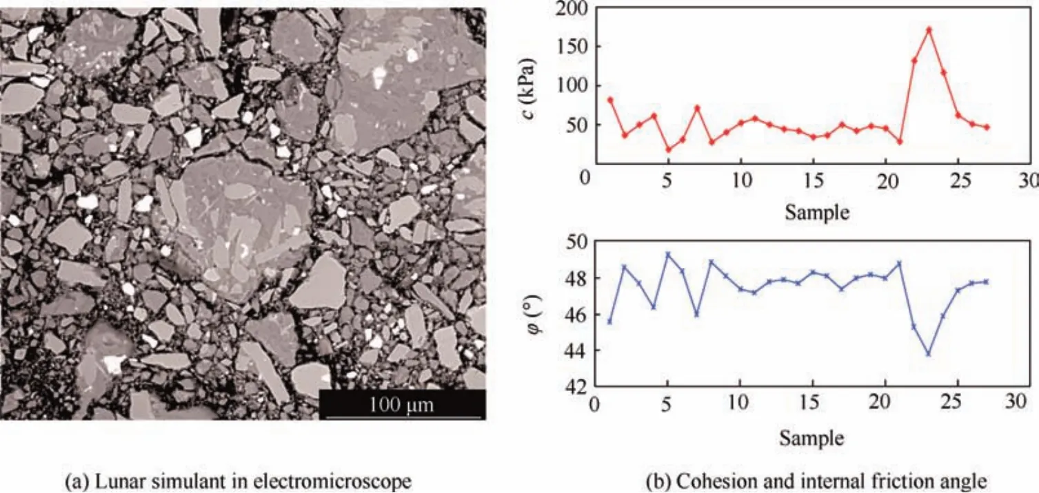
Fig.1 One typical lunar regolith simulant:HIT-LS1#soil.
2.2.Drill tool
The drill tool used in our experiments consists of a drill bit and a hollow auger.In this paper,a double-helix drill tool with double cutting blades is designed.The total length of this drill tool is approximately 0.5 m.There are two tungsten carbide cutting blades fixed to the drill bit matrix by a spotting weld process.To ensure that the cuttings can be removed from the auger flute fluently,the rake face of the cutting edge is aligned with the exit of the spiral auger flute.Taking the cuttings’removal effect and the drill bit’s stress situation into account,the straight welded insert mode is adopted to install the cutting blades.21The rotary drill is designed as a split structure,in which the upper and lower bodies are connected by a trapezoidal thread.Former drilling experiments have shown that this double-helix drill tool has a good cutting performance and allows to remove cuttings ranging from granular regolith to hard rock quite well.Hence,the drilling load modeling in this paper will be based on this type of drill tool.To analyze the effects of various drilling parameters and the lunar regolith’s mechanical parameters on the drilling load,the structural parameters of this drill tool are defined in Fig.2 and listed in Table 1.
2.3.Flexible tube coring method
In a drilling process,the drill tool is driven by a rotary and percussive driving mechanism and a penetrating mechanism to pierce into the regolith.Inside the auger,there is an elaborately designed flexible tube coring mechanism,as shown in Fig.3.There is a set of coring tubes inside the rotary auger,including a rigid tube and a flexible tube.The flexible tube is arranged between the auger and the rigid tube.One tip of the flexible tube is a sealing mechanism and the other tip is fixed on the connection component,connected with a dragging wire.
Once the drill bit contacts the planetary surface under the penetrating velocityvp,one tip of the dragging wire will be fixed at a point on the probe.Moreover,the wire keeps a tense state in the whole penetrating process.The rigid tube moves downward with the auger synchronously,however,it does not rotate.When drilling into the regolith,the flexible tube begins to wrap the cutting core under the winding speedvw.Since there is no relative locomotion between the flexible tube and the core,this coring method can keep the original stratif ication of planetary soil.When the desired drilling depth is reached,the sealing tip at the end of the flexible tube will be activated to collect the soil sample into the closed space.
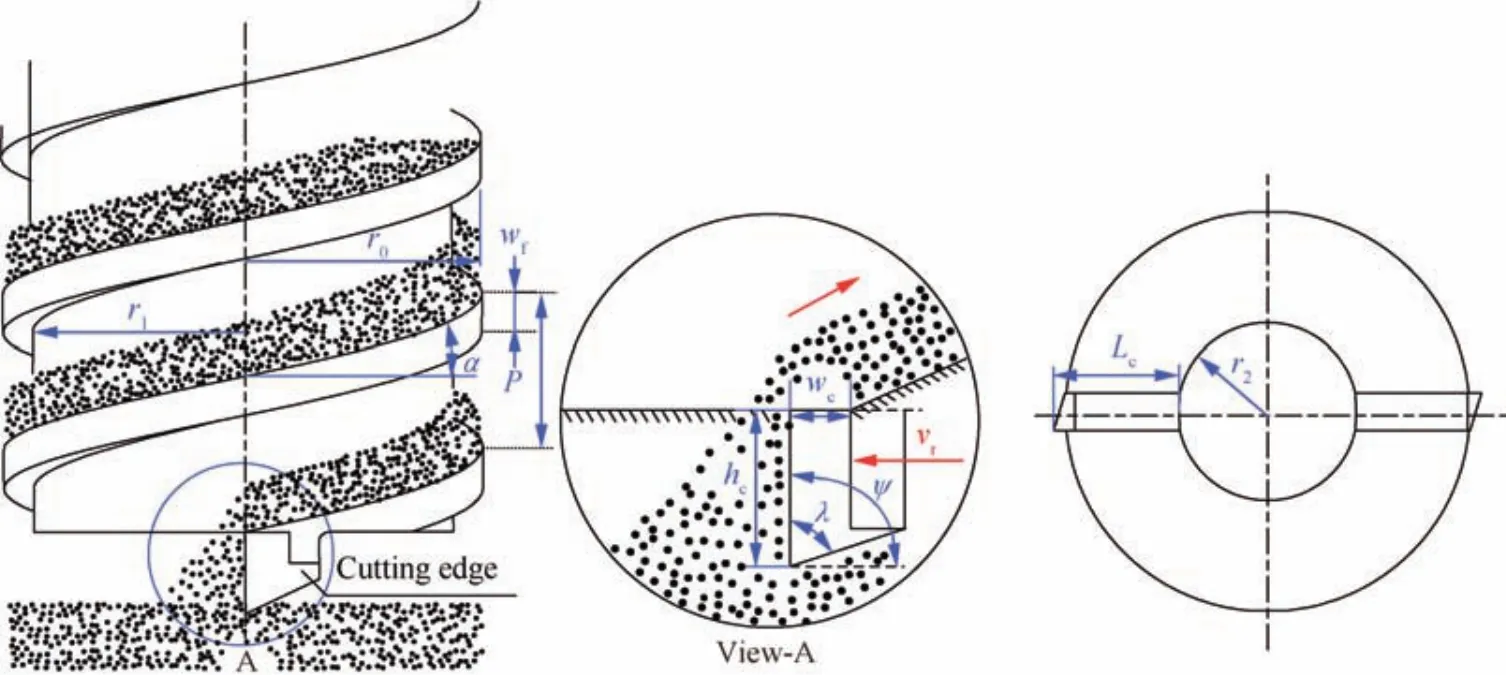
Fig.2 Definition of the drill tool’s structural parameters.
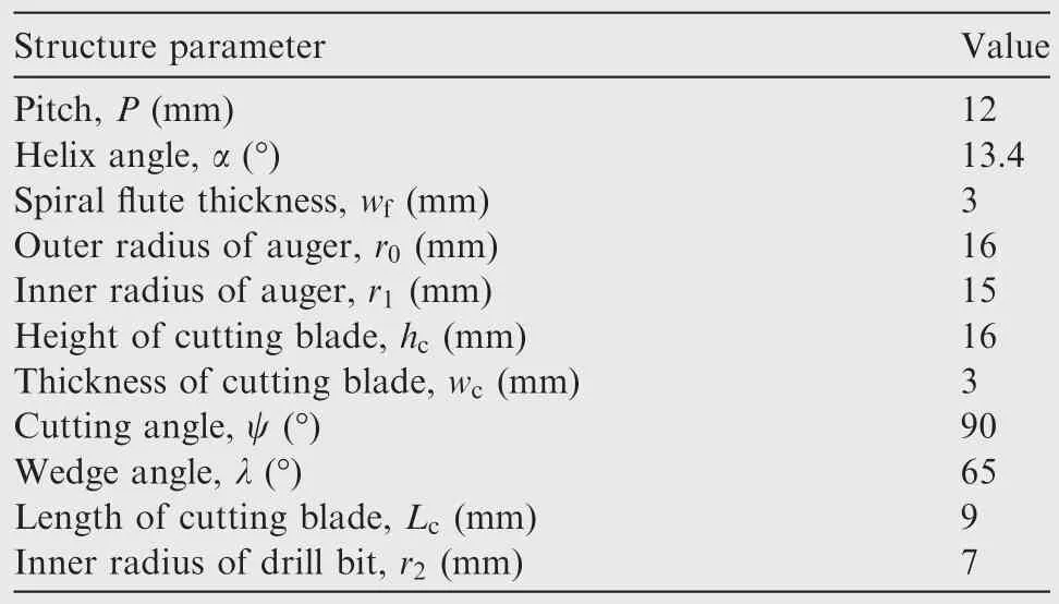
Table 1 Structural parameters of the drill tool.
2.4.Planetary drilling&coring test-bed
To validate the drilling load model,the authors of this paper developed a planetary drilling and coring test-bed(PDCT),as shown in Fig.4.The PDCT mainly consists of a bed frame,a lunar soil container,the drill tool,the penetrating drive unit,the rotary-percussive drive mechanism(RPDM),and the gravity compensation.22,23.A torque sensor is mounted on the output side of the rotary motor in order to monitor the rotary torque that the drill tool sustains,and an F/T sensor is installed on the bottom of the lunar soil container to monitor the penetration resistance force.Finally,on one side of the vertical rails,a magnetic scale displacement sensor is mounted to monitor the penetration velocity of the drill tool during the piercing process.To acquire the drilling loads online in drilling experiments,the data acquisition system of this test platform is based on xPC Target in MATLAB.
3.Conveyance mechanism
Under the complex motions of rotation and penetration,cuttings are immediately removed from the bottom of the borehole.This removal principle is similar to that of a screw conveyor.24,25Referring to the spiral transport theory,the driving force for upward removal of the lunar regolith along the spiral auger mainly contains the following two aspects:the thrust exerted by the bottom of the borehole and the friction exerted by the wall of the borehole.
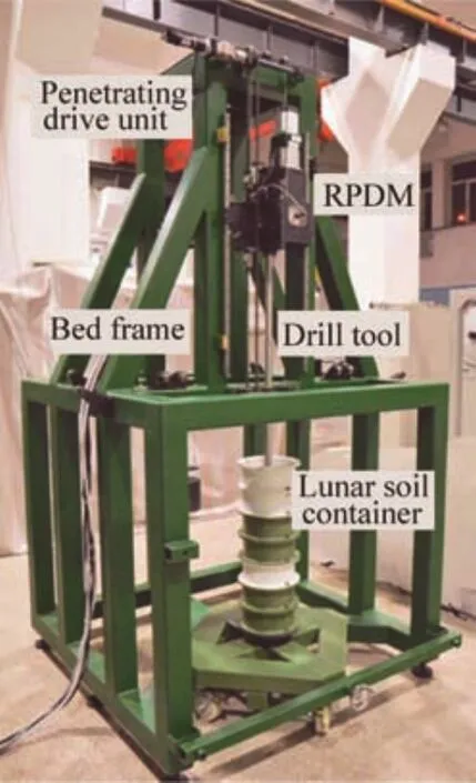
Fig.4 Planetary drilling and coring test-bed.
3.1.Thrust from the bottom of the borehole
Because the lunar regolith becomes loose and granular after the cutting action by the drill bit,the conveyance analysis will mainly be focused on the granular regolith,assuming that there is a homogeneous granular regolith on the smooth ramp with an inclination angle α,which is the same as the helix angle in Table 1.The lunar soil sustains the thrustFpfrom the bottom of the borehole,which causes an upward movement of the material along the ramp.The weight of lunar regolith of a thickness of 1,a length ofL,and a height ofsalong the ramp direction is ρgmssin α.According to Rankine passive earth pressure theory,26the maximum thrust acting on the lunar soil can be calculated as follows:
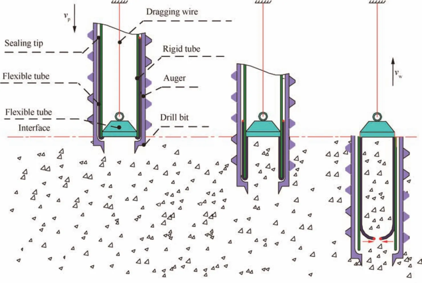
Fig.3 Flexible tube coring method.5

where ρ is the density of the granular soil andgmis the acceleration of gravity on the moon.The static equilibrium equations are given as follows:

Herein,Lsinα=H,whereHis the vertical height of the granular regolith.IncorporatingHinto the above equation and simplifying it,we obtain:

According to Eq.(3),the vertical heightHof the granular regolith is controlled by the regolith’s internal angle φ and heights.As shown in Fig.5,when keeping the height of regolith in the spiral flute constant,Hincreases with the inner angle.Due to the fact thatsis restricted by the drill pitchPand the blade thickness of the spiral flutehc,the maximum height will beP-hc.For the designed double-helix drill tool and the compacted lunar regolith,the calculated maximum height of the lunar regolith is only about 9 mm.
Under a non-choking condition,there is no additional stress on the soil and the thrust from the bottom of the borehole can only push the lunar regolith over a limited distance.Therefore,it can be concluded that the thrust from the bottom of the borehole is not the main driving force for cuttings’removal under a non-choking condition.However,under a choking condition,an additional stress occurs,which can enhance the thrust from the bottom of the borehole and should be considered in modeling.
3.2.Friction from the wall of the borehole
The friction along the wall of the borehole is generated by the positive pressure acting on the wall.For the granular regolith in the spiral flute,the main positive pressure stems from the following three aspects:the active earth pressure,the centrifugal force,and the additional stress.In the following,three positive pressures will be discussed.
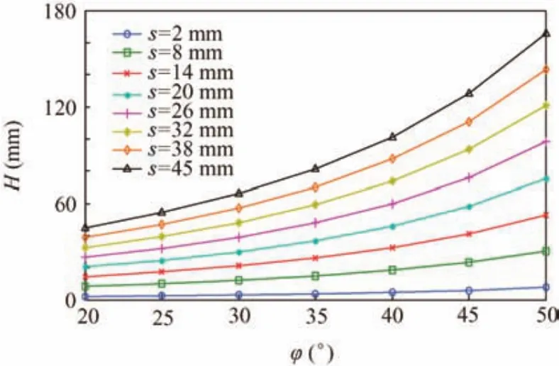
Fig.5 Vertical height by the thrust from the bottom of the borehole.
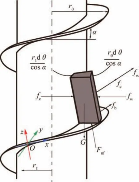
Fig.6 Force analysis under the active earth pressure.
Consider a sector element of the lunar regolith on the flute ramp,of which the height of the lunar regolith element iss.As shown in Fig.6,the Cartesian coordinate systemO-xyzfor force and motion analysis is built on the surface of the spiral flute,whereFcis the reaction force on the cylindrical surface of the auger,Fwis the reaction force on the wall of the borehole,Fnfis the supporting force on the bottom of the flute,andGis the gravity of the lunar regolith element.
According to the active earth pressure theory,the positive pressure acted on the lunar regolith σyat a drilling depthhis calculated as follows:

By analyzing the force states of a lunar regolith element,the resistances on the wall of the boreholefw,at the bottom of the spiral flutefb,and on the ceiling of the spiral flutefccan be acquired:

where dθ is the circumference angle of the lunar regolith element,μsis the friction coefficient between the soil and the spiral flute,and μwis the friction coefficient between the soil and the wall of borehole.Assuming that the action by the active earth pressure can convey soil upward,the deviation from the statics equilibrium is illustrated as follows:


If the friction coefficient μsis equal to the friction coeff icient μw,the following inequality can be acquired by connecting the above division and statics equilibrium inequality.whereKapis defined as the pushing coefficient of the soil’s active earth pressure.IfKap>1,this means that the lunar regolith can be moved upward along the spiral flute by the active earth pressure.Otherwise,it cannot realize that the removal of the borehole cuttings cannot be achieved by the active pressure.As shown in Fig.7,when the soil has a particular height,Kapis smaller for a high internal angle of the lunar regolith and is always below 1.This can be explained that the active earth pressure based on the active earth pressure theory is negatively correlated with the soil’s inner angle,which results in a smaller friction force to drive the soil to be removed up.Therefore,the pushing coefficient of the soil’s active earth pressureKapbecomes larger when the inner angle decreases.
According to the spiral transport theory,there exists a threshold of the auger’s rotary speednt.When the auger’s rotary speednexceeds the speed thresholdnt,soil will be removed from the spiral flute fluently.In the following,a volume element of the lunar regolith element residing on the spiral flute is analyzed.Under a non-choking condition,the soil element will slide to the side of the hole wall due to the centrifugal force,as shown in Fig.8(a),where the Cartesian coordinate systemO-xyzfor force and motion analysis is built on the surface of the spiral flute,Fceis the centrifugal force,Ffnfis the friction force produced from the normal forceFnf,andˉris the average radius of the lunar soil.
When the auger’s rotary speed exceeds the threshold,soil will come into contact with the borehole wall and then the relative motion begins.Moreover,the direction of soil’s absolute speed changes.As shown in Fig.8(b),in this condition,vris the relative velocity,vfis the following velocity by the rotary speed,vpis the penetrating velocity,vais the absolute velocity,and β is the angle between the speed vector and the horizontal surface.The auger’s rotary speed won’t be too high,because it is restricted by the power supplied by the probe.Thus,the Coriolis force can be neglected in the force analysis.As shown in Fig.8(c),Fwchanges the direction when the rotary speed exceeds the threshold.The force equilibrium equations of the lunar regolith are given as follows:

Based on the velocity triangle,the lunar regolith motion equations can be obtained as follows:

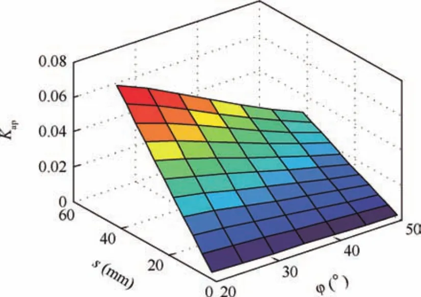
Fig.7 Pushing coefficient of the soil’s active earth pressure.
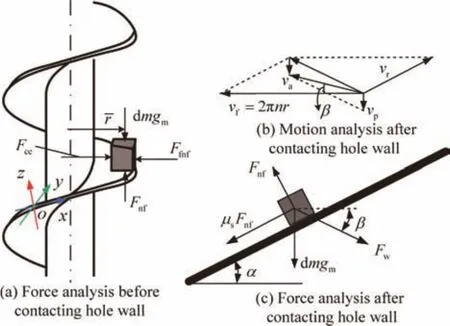
Fig.8 Force analysis under the centrifugal force under a nonchoking condition.
Combining Eqs.(8)and(9),the lunar soil’s helix angle and the relative velocity under a non-choking drilling condition will be acquired.
As long as the rotary speed of the auger is below the rotary speed threshold,the lunar regolith may not be conveyed by the centrifugal force.Meanwhile,the annular region between the coring tube and the auger’s outer surface may be filled with the lunar regolith,producing additional stress.As shown in Fig.9,a sector element of the lunar regolith filling in the flute ramp under a choking condition is analyzed.The Cartesian coordinate systemO-xyzis built on the surface of the spiral flute.
Under a choking condition,the lunar soil element in the flute sustains the actions from the spiral blade,the wall of the borehole,and the cylindrical surface of the auger.By both actions(the thrust exerted by the bottom of the borehole and the friction exerted by the wall of the borehole),the lunar regolith element will be removed along with the spiral flute,in which the soil’s motion is very similar to that under a nonchoking condition.The force and torque equations are given as follows:

whereFceis the centrifugal force sustained of the lunar regolith,Fpis the thrust from the borehole,Fnwis the normal force on the wall of the borehole,Fnfis the normal force on the bottom of the flute,Fσcis the normal force on the ceiling of the flute by the additional stress,Fσsis the normal force on the cylindrical surface by the additional stress,Ffcis the friction force from the spiral flute’s ceiling,Ffsis the friction force from the auger’s cylindrical surface,andFfwis the friction force from the hole wall.
For a stationary situation,the volume of cuttings produced must be equal to the volume of cuttings removed from the borehole.This can be expressed by the following equation:

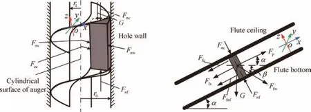
Fig.9 Force analysis under additional stress under a choking condition.
Combining Eqs.(10)and(11),the additional stress under a choking condition can be acquired.As shown in Fig.10,the additional stress of one lunar regolith simulant with an internal angle of 30°is calculated.From this figure,under a certain penetrating velocity,the additional stress increases when the rotary speed slightly decreases.This can be concluded that a higher rotary speed can relieve the choking condition.For a given rotary speed,the additional stress increases with the penetration velocity,showing that a low penetration velocity will be helpful for removing the lunar regolith.
3.3.Filling rate of auger flute(FRAF)
According to the above analysis of a lunar soil’s conveyance mechanism,the filling condition of the spiral flute directly affects the auger’s stress state.To acquire an accurate drilling model,the filling rate of auger flute(FRAF)Kfis proposed as:

whereS0is the transversal area of the auger flute andS1is the actual transversal area of the lunar soil removed by the auger flute.Based on the analysis of drilling conditions under different rotary speeds,drilling conditions can be divided into two typical cases.When 0<n<nt,cuttings will be accumulated on the spiral flute until filling the flute,producing a choking condition.Whenn>nt,cuttings will be removed by the centrifugal force,and the spiral flute will not be filled with cuttings,producing a non-choking condition.
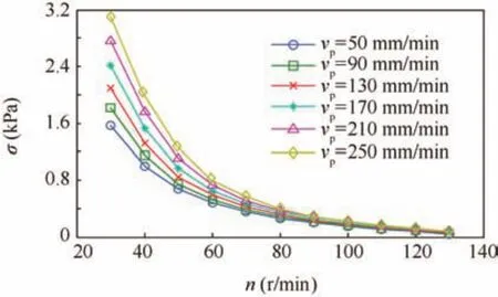
Fig.10 Additional stress under a choking condition.
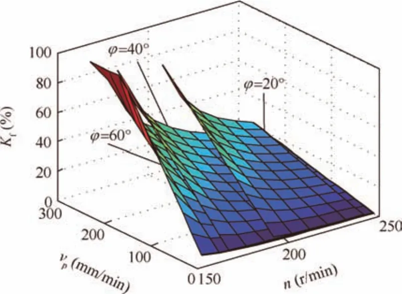
Fig.11 FRAF Kfcalculated in different conditions.
Combining Eqs.(8),(9),and(12),Kffor different rotary speeds and penetration velocities can be obtained,as presented in Fig.11.For a certain lunar regolith simulant,under the same rotary speed condition,Kfis closer to 100%when the penetration velocity is higher.Under the same penetration velocity,Kfis closer to 100%when the rotary speed is lower untiln<nt.Since the friction force from the wall of the borehole is the main driving force for removing cuttings,a lunar regolith with a larger internal angle is easier to be conveyed,and the correspondingKfis smaller.
4.Modeling and validation
Based on the analysis of the conveyance mechanism in Section 3,a drilling load model describing a combination of the auger and the drill bit is presented now.Actually,according to the flexible tube coring method,there is no relative locomotion between the core and the sleeve.Compared with the drilling loads in the auger and the drill bit,the force or toque generated by the friction between the core and the sleeve may be very little,which could be neglected in the drilling load’s modeling.Since drilling conditions can be classified by the FRAF index,the models for the auger and the drill bit will firstly be considered separately,taking possible drilling conditions into account.The total drilling load can then be acquired by adding up these two contributions.
4.1.Drilling load modeling
According to the motion and force analysis of lunar regolith presented in Section 3,the drilling loads on the auger mainly contain the following six parts.As shown in Fig.12,Fafis the friction force acting on the spiral blade.Since the lunar regolith simulant is compressed to keep homogenous,the drilled borehole can be held well in the course of a drilling operation and the wall of the borehole will be rather smooth.Hence,for calculating drilling loads,the friction force on the spiral bladeFafcan be neglected.
Under a non-choking condition,the drilling loads on the auger mainly contain the supporting force and the force on the bottom of the spiral flute.Deploying the spiral line,the deploying angle of the lunar regolith at a certain heighthcan be acquired as χ =h/(ˉrsin α).In a non-choking condition,the rotary torque and penetration force that drill tool sustains can be obtained as follows:

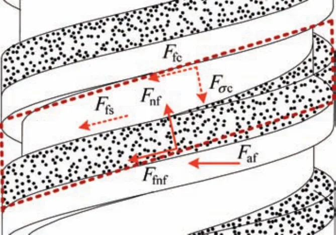
Fig.12 Drilling loads on the auger in two conditions.
whereNtis the number of the auger’s spiral line.Combining Eqs.(12)and(13)together,the drilling loads on the auger in a non-choking condition can be acquired.
Under a choking condition,the cuttings in the spiral flute will be extruded and conveyed.In this drilling condition,the auger not only sustains the supporting force and the force on the bottom of the flute,but also sustains the supporting force and the force on the flute ceiling as well as the force on the cylindrical surface.At a certain height,the rotary torque and penetration force sustained by the drill tool can be calculated as follows:

Since the filling rate of auger fluteKf=1 in a choking condition,combining Eqs.(10),(11),and(14),the drilling loads on the auger in a choking condition can be acquired.
According to the difference in failure mechanism,the lunar regolith surrounding the drill bit can be divided into two parts:the cutting area and the accumulation area.27The lunar regolith in the cutting area mainly sustains the shearing damage by the cutting blade,and the cuttings in the accumulation area are mainly removed by the wall of the borehole.As shown in Fig.13,according to the difference in boundary constraint,the accumulation area can be divided into accumulation zoneA1and zoneB1.
Accumulation zoneA1,formingatriangularwedgeAFQ-BGP,is connected with the cuttings in the spiral flute.Accumulation zoneB1is restricted by the transition plane and forms a trapezoidal shape wedgeBSMJ-CHNK.
According to the morphological analysis of the soil in the drill bit,the drilling loads on the drill bit mainly contain the following nine contributions,as shown in Fig.14.Compared with the accumulation area,the area of cutting is too small,so the cohesion forceFccand the friction forceFcfin the cutting area are neglected.The specific components of the drilling loads on the drill bit are given in Table 2.
Under a non-choking drilling condition,the cuttings in the accumulation area only sustain a tangential load.This implies that the penetration force in the accumulation areaFpa=0.The drilling loads in a non-choking drilling condition are mainly caused byFaf1and the cohesion forceFac1between cuttings in the accumulation area and the wall of the borehole,Faf2and the cohesion forceFac2,and the Rankine passive earth pressureFcp.Each drilling load component,the rotary torque,and the penetration force are as follows:
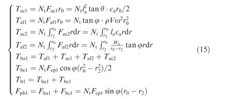
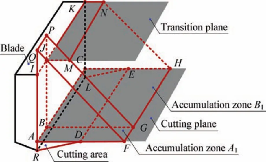
Fig.13 Morphological analysis of the soil surrounding the drill bit.
wherecais the cohesion of the cuttings in the accumulation area,Wais the weight of the cuttings in the accumulation area,andlais the length of the bottom of the accumulation area.Combining Eqs.(11)and(15),drilling loads on the drill bit in a non-choking condition can be acquired.
In a choking drilling condition,cuttings in the accumulation area bear the action by the additional stress and are removed by the extruding action.The shape of the accumulation area is a closed wedge,where the accumulation angle θ=α and the filling rate of auger fluteKf=1.In addition to the drilling loads in a non-choking condition,the drill bit also sustains the supporting forcesFσtandFσc,as well as the friction forcesFaf3andFaf4from the transition plane and the ceiling plane of the spiral flute,respectively.Each component of the drilling loads,the rotary torque,and the penetration force in a choking condition are as follows:
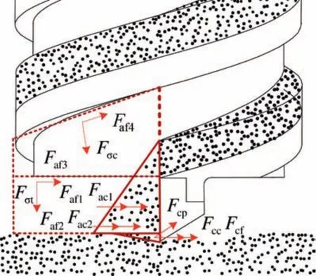
Fig.14 Drilling loads on the drill bit in two conditions.
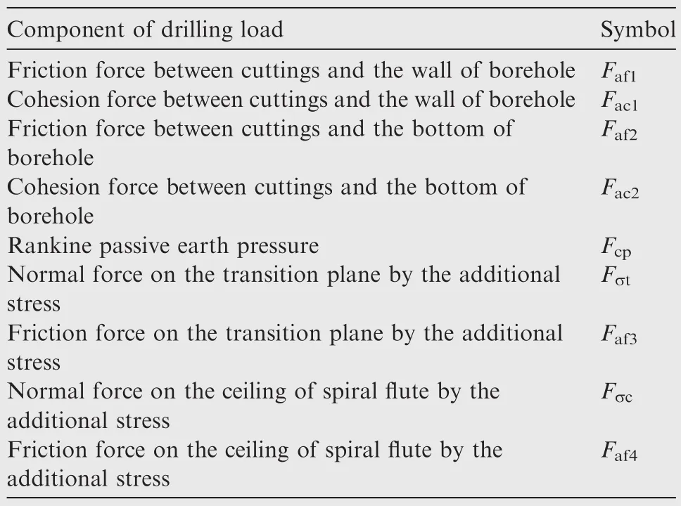
Table 2 Components of the drilling load on the drill bit.

Combining Eqs.(10),(11),and(16),the drilling loads on the drill bit in a choking condition can be acquired.In summary,by evaluating the filling rate of auger flute(FRAF)index,the piercing process with different drilling parameters can be classified as either a non-choking condition or a choking condition.After calculating the drilling loads on the auger and the drill bit respectively,the total drilling load is obtained by adding up the two components.
4.2.Model validation
When conducting the drilling and coring experiments,a flexible tube of 130-mm length is positioned in the hollow auger,as showninFig.15.Once thedrillbitisincontactwith thesoilsurface,one tip of the dragging wire is fixed at a point on the test platform,while the other tip is connected to the starting point oftheflexibletubeandiskeptinatensestate.5Whenthedesired drilling depth is reached,the sealing tip at the end of the flexible tubeisactivatedtocollectthecoringsampleintotheclosedspace insidetheflexibletube.Todistinguishthecuttingsremovedwith those in the spiral flute,an isolation plate was mounted on the surface of the lunar regolith passing through the auger.
Drilling parameters in the drilling and coring experiments are given as follows:rotary speedn=40,80,120,160,200,240 r/min and penetrating velocityvp=40,80,120,200,240 mm/min.According to the 6×6 matrix,repeated tests are conducted.In the experiments,drilling loads are monitored,not exceeding the maximum drilling loads that test platform can sustain.The test results on the HIT-LS1#lunar regolith simulant are shown in the above figure.
According to the discussion in Section 3,the FRAF is applied in our drilling loads model to determine drilling conditions.To verify the correctness of the proposed FRAF concept,verification tests should be carried out.Neglecting the effect on the soil’s density by the drilling depth,the FRAFKfcan be equivalent to the mass ratio between the actual mass in the spiral fluteM2and the theoretical oneMs,as shown in Eq.(17):

During the drilling process,three types of lunar regolith are produced:accumulation soilMa(H),soil in the spiral fluteMs(H),and coring soilMc(H).According to the conservation of mass,the following equation can be obtained:


Fig.15 Working process of drilling and coring experiments.
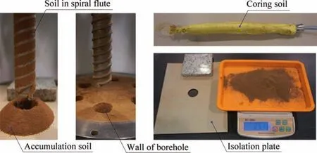
Fig.16 Working process of drilling and coring tests.
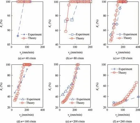
Fig.17 FRARs in theory and experiment.
Since the soil in the spiral flute is in a confined space,its mass cannot be measured accurately.Herein,to a certain depthH,Ms(H)can be indirectly acquired by measuring the mass of the accumulation soilMa(H)and that of coring soilMc(H)separately,as shown in Fig.16.
Using the mechanical parameters of the lunar regolith simulant in Eq.(12),a comparison of results between the theoretically calculated FRAF and the FRAF obtained from the experiments can be made.The results are shown in Fig.17.This comparison indicates that the calculated FRAF coincides with the test results quite well.With the same rotary speed,the FRAF increases with the penetration velocity and at a higher velocity,the FRAF changes significantly.The FRAF becomes smaller when the rotation speed is higher.At a low rotation speed and a high penetration velocity,the FRAF is always equal to 1,which means that the drill tool gets blocked in this drilling parameters regime.At a high rotary speed,the FRAF is constantly less than 1,meaning that the drill tool is not blocked and thus the cuttings in the spiral flute are removed fluently.The experimental results presented above show that the proposed FRAF concept can describe the drilling conditions in different drilling parameter ranges quite well and thus can be used to establish the drilling load model.
In addition to the masses of the accumulation soil and the coring soil,drilling loads are also acquired by the drilling and coring process.The mechanical parameters of the lunar regolith simulant in our drilling load model and the comparison results between theoretical and experimental rotary torques are shown in Fig.18.
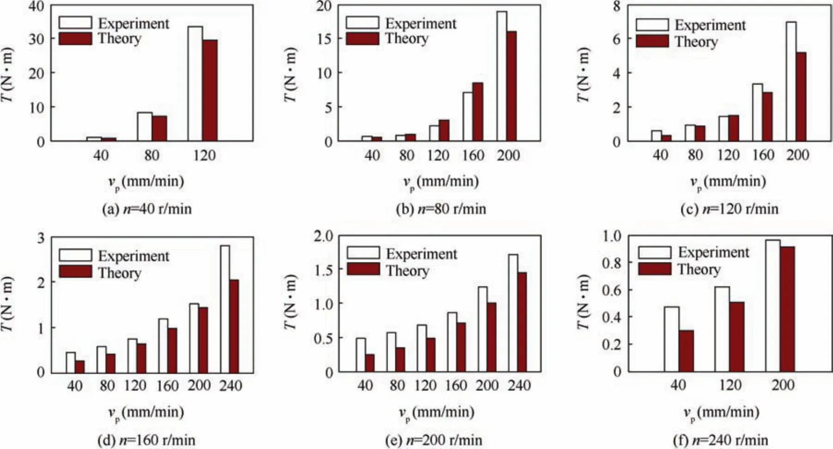
Fig.18 Drilling loads in theory and experiment.
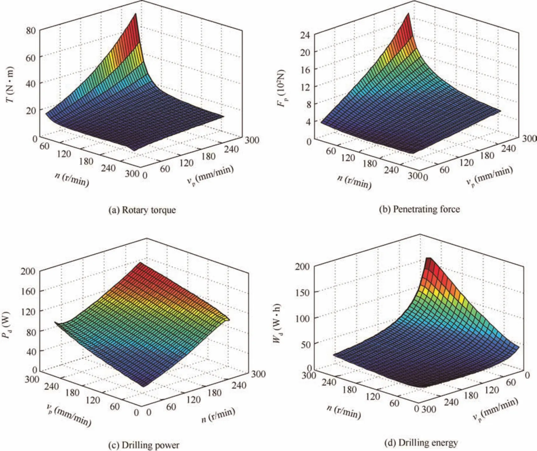
Fig.19 Predicted drilling loads based on the established drilling load model.
From the rotary torque comparison results shown in Fig.18,the calculated rotary torque obtained from the theo-retical model also coincides well with the test results.Under the same rotary speed,the rotary torqueTincreases with the penetration velocity significantly.At a high penetration velocity,the rotary torque changes significantly,and at a low penetration velocity,the growth of the rotary torque becomes more moderate.This can be explained by the fact that a high penetration velocity leads to increases of the cutting volume and the FRAF,causing more easily a blocking of the drilling tool.Under the same penetration velocity,the rotary torqueTbecomes smaller when the rotary speed is higher.At a high rotary speed,the rotary torque changes significantly,and at a low rotary speed,the growth of the rotary torque becomes moderate.When the penetration velocityvp=120 mm/min,the rotary torque reaches 34 N.m,almost the maximum drilling load that test platform can sustain.As shown in Fig.18(f),a high rotary speed results in an increase of the centrifugal force,so cuttings can be removed fluently and the corresponding rotary torque is less than 1 N.m.
5.Drilling parameters optimization
The goal of drilling load modeling is to acquire suitable drilling parameters for different drilling conditions and thereby to improve the sampling drill’s environmental adaptability.Based on the drilling model validated in Section 4,the drilling load in one simulant was obtained.According to the lunar exploration requirements,drilling parameters of this simulant can be optimized reasonably under limited drilling power,penetration force,etc.
5.1.Optimization indexes
Due to limited in-orbit weight and power supply,a lunar sample return mission has several requirement indices.These can be divided into safety index and functional index.The safety index is proposed to confirm the mission’s reliability and must be obeyed.The functional index indicates to which extent the system has been optimized to fulfill its foreseen task effectively.Suitable drilling parameters should satisfy the requirements of both the safety index and the functional index.
Restricted by the driving capacity of the rotary motor,the rotary torqueTshould not be more than 30 Nm.By the lander weight constraint,the penetration forceFpshould be less than 800 N.By the probe’s power supply capacity constraint,the drilling powerPdand the energyWdare required to be less than 100 W and 50 W h,respectively.Since the main goal of lunar drilling and coring is to acquire lunar regolith,the sampling rateKshould not be too low.Herein,the sampling rateKis required to be more than 90%.According to experimental research on the ground,overlong drilling time will lead to a decrease of the sampling rate.28Therefore,the total drilling timeTtis restricted to be 0.5 h for a 2-m depth and the corresponding penetrating velocityvpshould be more than 80 mm/min.
5.2.Optimization method
Since the intended landing spot in China’s future lunar exploration mission is the rainbow bay area on the Moon,the lunar regolith acquired by the Apollo15 mission at the ‘Hadley Rile”is chosen as the drilling formation.29.Taking the mechanical parameters of this lunar regolith into the drilling load model established in Section 4,the corresponding rotary torque,penetrating force,drilling power,and drilling energy are acquired,as shown in Fig.19.
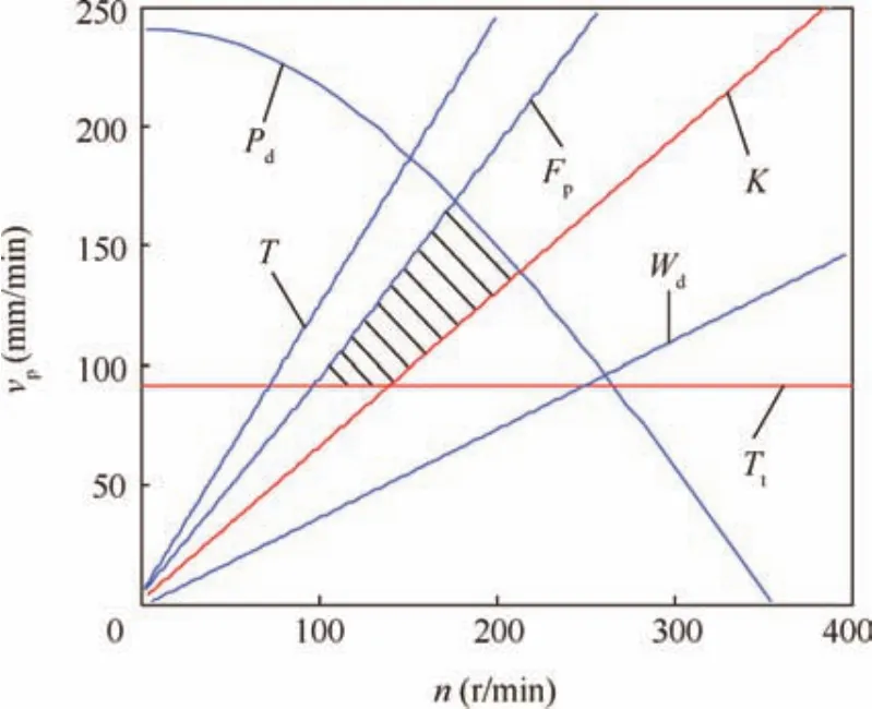
Fig.20 Range of suitable drilling parameters.
The relationship between the sampling rateKand the ratio ofvptonwas discussed in former experimental research.28.The rotary speednand the penetration velocityvpare restricted by the above optimization indexes,as shown in Fig.20.The black shaded region in Fig.20 corresponds to the drilling parameter values meeting the requirements of the tasks.
According to the principle of least energy consumption in metal cutting theory,there exists an appropriate combination of drilling parameters(no,vpo,fpero)minimizing the drilling total energy,as shown in the following equation:30

wherenois the optimized rotary speed,vpois the optimized penetrating velocity,Tois the optimized rotary torque,Fpois the optimized penetrating force,Ttois the optimized drilling total time,andWdminis the optimized drilling energy.Using the mechanical parameters of lunar regolith in the above equation,the optimized drilling parameters are as follows:rotary speedno=85 r/min and penetration velocityvpo=80 mm/min.The minimum drilling energy for drilling a 2m depthWo=38.56 Wh,and the optimized coring rateKo=94.6%,meeting all the requirements for the future task.
6.Conclusions
This paper analyzes the failure mode and conveyance state of the lunar regolith.The filling rate of auger flute(FRAF)is proposed to classify drilling conditions into two typical conditions:non-choking and choking conditions.Based on the spiral transport theory,a drilling load model combing the loads on the auger and the drill bit has been established.Experiments in one typical lunar regolith simulant HIT-LS1#soil under different combinations of drilling parameters indicate that this drilling load model based on the FRAF coincides with the test results reasonably well.Based on this drilling load model and optimization indices analyzed,drilling parameters of the lunar regolith simulant can be optimized by using the principle of least energy consumption.
Acknowledgments
TheauthorsthankthesupportsbytheNationalNaturalScience Foundation of China(No.61403106,No.51575122),Program of Introducing Talents of Discipline to Universities(No.B07018)of China,and Fundamental Research Funds for the Central Universities(No.HIT.NSRIF.2014051)of China.
Appendix A.Supplementary material
Supplementary data associated with this article can be found,in the online version,at http://dx.doi.org/10.1016/j.cja.2016.05.003.
1.Ronca LB.An introduction to the geology of the moon.Proc Geol Assoc1966;77(1):101–25.
2.Ouyang ZY,Li CL,Zou YL,Liu JZ,Liu JJM.The primary science result from the chang’e-1 probe.Sci China Earth Sci2010;40(3):261–80.
3.Bar-Cohen Y,Zacny K.Drilling in extreme environment:penetration and sampling on earth and other planets.Weinheim:Wiley-VCH;2009.p.1–30.
4.Zacny K,Bar-Cohen Y.Drilling and excavation for construction and in-situ resource utilization.In:Badescu V,editor.Mars prospective energy and material resources.Berlin:Springer-Verlag;2009.p.431–59.
5.Quan QQ,Tang JY,Jiang SY,Li H,Li SC,Deng ZQ,et al.Control system for a drilling&coring device in lunar exploration.Proc of the IEEE international conference on information and automation,2013 Aug.26–28;Yinchuan,China.Piscataway,NJ:IEEE Press;2013.p.79–84.
6.Shi XM,Deng ZQ,Quan QQ,Tang DW,Hou XY,Jiang SY.Development of a drilling and coring test-bed for lunar subsurface exploration and preliminary experiments.Chin J Mech Eng2014;27(4):673–82.
7.Heiken GH,Vaniman DT,French BM.Lunar sourcebook:a user’s guide to the moon.Paris:Cambridge University Press;1991.p.285–356.
8.Lian Y.Inversion of composition and analysis of structure in the lunar subsurface from chang’e microwave data[dissertation].Changchun:Jilin University;2014[Chinese].
9.Shi XM,Jie DG,Quan QQ,Tang DW,Jiang SY,Deng ZQ.Experimental research on lunar soil simulant drilling load analysis.Chin J Astronaut2014;35(6):648–56.
10.Zhong Z.Theoretical and experimental analysis of the compaction process in a tapered screw press[dissertation].Newcastle:The University of Newcastle upon Tyne;1991.
11.Robert A,Willis A.Performance of grain augers.Proc of the institute of mechanical engineers,vol.176,8.p.165–94.
12.Zacny K,Quayle MC,Cooper GA.Laboratory drilling under martian conditions yields unexpected results.J Geophys Res2004;109(1):E07S16.
13.Zacny K.Mars drilling-an investigation and development of techniques for drilling exploratory boreholes on mars[dissertation].Berkeley:University of California,Berkeley;2005.
14.Tian Y,Deng ZQ,Tang DW,Jiang SY,Hou XY.Structure parameters optimization and simulation experiment of auger in lunar soil drilling-sampling device.Chin J Mech Eng2012;48(23):10–5.
15.Deng ZQ,Tian Y,Tang DW,Jiang SY,Quan QQ,Xiao H.Research on new structure coring bit for extraterrestrial bodies exploration.Chin J Mech Eng2013;49(19):104–10.
16.Vrettos C.Shear strength investigation for a class of extraterrestrial analogue soils.J Geotech Geoenviron Eng2012;138(4):508–15.
17.Williams DE.To a rock moon:a geologist’s history of lunar exploration.Tucson:University of Arizona Press;1994.p.137–49.
18.Butler JC,King EA.Analysis of grain size frequency distributions of lunar fines.Proc of 5th lunar planet science conference.p.829–41.
19.Mitchell JK,Bromwell LG,Carrier III NC,Costes NC,Scott RF.Soil mechanical properties at the apollo 14 site.J Geophys Res1972;77(29):5641–64.
20.Mitchell JK,Houston WH,Scott RF,Bromwell L.Mechanical properties of lunar soil:density,porosity,cohesion and angle of internalProc of the third lunar science conference.p.3235–53.
21.Yan T.Rock and soil drilling technology.Wuhan:Chinese University of Geoscience Press;2001.p.65–92[Chinese].
22.Shi XM,Tang DW,Quan QQ,Jiang SY,Hou XY,Deng ZQ.Development of a drilling and coring test-bed for lunar subsurface exploration.Proc of the IEEE international conference on robotics and biomimetics,2013 Dec.12–14;Shenzhen,China.Piscataway,NJ:IEEE Press;2013.p.2124–9.
23.Quan QQ,Li P,Jiang SY,Hou XY,Tang DW,Deng ZQ,et al.Development of a rotary-percussive drilling mechanism(rpdm).Proc of the IEEE international conference on robotics and biomimetics,2012 Dec.11–14;Guangzhou,China.Piscataway,NJ:IEEE Press;2012.p.950–5.
24.Ross I,Isaace G.Capacity of enclosed screw conveyors handling granular materials.Trans Am Soc Agric Eng1961;4(1):97–104.
25.Mellor M.Mechanics of cuttings and boring.USA Army Cold Regions Research and Engineering Laboratory;1981,Report.
26.Collins JA.Failure of materials in mechanical design:analysis,prediction,prevention.New York:Wiley;1993.p.105–85.
27.Tang JY.Research on drilling strategy of lunar drilling and coring based on real-time recognition of drillability[dissertation].Harbin:Harbin Institute of Technology;2014[Chinese].
28.Shi XM,Quan QQ,Tang DW,Jiang SY,Hou XY,Deng ZQ.Experimental research on drilling and sampling of lunar soil simulant.Appl Mech Mater2012;233(1):218–23.
29.Richard WO,David MH.Apollo the definitive sourcebook.Chi Chester:Springer;2006.p.425–69.
30.ShiH.Metalcuttingtheoryandpracticalnewperspective.Wuhan:Huazhong University of Science and Technology Press;2003.p.201–26[Chinese].
1 February 2016;revised 14 March 2016;accepted 8 April 2016
Available online 15 October 2016
?2016 Chinese Society of Aeronautics and Astronautics.Production and hosting by Elsevier Ltd.This is anopenaccessarticleundertheCCBY-NC-NDlicense(http://creativecommons.org/licenses/by-nc-nd/4.0/).
*Corresponding authors.Tel.:+86 451 86413587.
E-mail addresses:quanqiquan@hit.edu.cn(Q.Quan),jiangshy@hit.edu.cn(S.Jiang).
Peer review under responsibility of Editorial Committee of CJA.
 CHINESE JOURNAL OF AERONAUTICS2017年1期
- CHINESE JOURNAL OF AERONAUTICS的其它文章
- Anti-plane problem of four edge cracks emanating from a square hole in piezoelectric solids
- Stress analysis and damage evolution in individual plies of notched composite laminates subjected to in-plane loads
- An adaptive attitude algorithm based on a current statistical model for maneuvering acceleration
- Spacecraft attitude maneuver control using two parallel mounted 3-DOF spherical actuators
- Angular velocity determination of spinning solar sails using only a sun sensor
- Automatic landing system using neural networks and radio-technical subsystems
