
Design and control of coaxial switching system for ion cyclotron wave resonance heating system of EAST
2020-05-06 05:59:36JianCHENG程健GuangLIU劉廣GenCHEN陳根YanpingZHAO趙燕平XuDENG鄧旭YuzhouMAO毛玉周andLunanLIU劉魯南
Plasma Science and Technology 2020年4期
關鍵詞:魯南
Jian CHENG (程健),Guang LIU (劉廣),Gen CHEN (陳根),Yanping ZHAO (趙燕平),Xu DENG (鄧旭),Yuzhou MAO (毛玉周) and Lunan LIU (劉魯南)
1 Institute of Plasma Physics,Chinese Academy of Sciences,Hefei 230031,People’s Republic of China
2 University of Science and Technology of China,Hefei 230026,People’s Republic of China
Abstract
Keywords: EAST,ICRH,coaxial switching system,MODBUS
1.Introduction
Ion cyclotron wave resonance heating system(ICRH)which is one of the most important auxiliary system in EAST provides conditions for heating the plasma[1].ICRH consists of a phaseshiftable radiofrequency (RF) signal source,eight 1.5 MW high-power transmitters,eleven coaxial switches,transmission lines,matching networks,decoupling branches,and antennas[2–4].In the original coaxial control system,a single-chip microcomputer is used as the control chip and several relays are responsible for determining the position information of the coaxial switch.A programmable logic controller (PLC) identifies these relay signals to control the coaxial switch remotely.However,the signals transmission between the relay and PLC may be wrong due to environmental electromagnetic interference in ion cyclotron laboratory.The coaxial switch control system was upgraded to solve the problems.This paper mainly introduces the upgraded design and control of the coaxial switch system.The section 2 introduces design of the single coaxial switch and composition of the whole coaxial switching system network.The control method of the coaxial switching system is developed to achieve the required state in section 3.The controller core of hardware circuit is realized by using field programmable gate array (FPGA) [5].The master computer’s control program is written in LabVIEW [6].The MODBUS communication protocol is utilized as the communication mode between the master computer and each coaxial switch controller[7].In the end,tests have been done to verify the correct operation of the system.
2.Design of the coaxial switching system
2.1.Design of the single coaxial switch
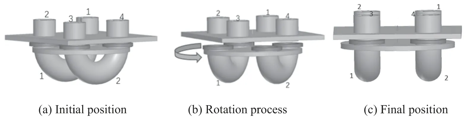
Figure 1.Switching process of the single coaxial switch.

Figure 2.The entity of the single coaxial switch.
A single coaxial switch has four ports (from Port 1 to Port 4)connected by fixed transmission lines.As shown in figure 1(a),two 180°elbow transmission lines fixed on the bottom platform of the coaxial switch are liftable and rotatable.A servo motor and an ordinary motor which are placed below the coaxial switch contribute to the switching.The servo motor is applied to the lifting process and the ordinary motor is used to the rotation process.Four proximity switches are used to determine the position information as shown in figure 2.
The switching process is displayed in figure 1.The elbow transmission line 1 connects Port 1 and Port 2 and the elbow transmission line 2 connects with the other two ports.The servo motor starts to work after receiving the command of the coaxial switch controller.The bottom platform descends to the position of down proximity switch and then rotates to the right proximity switch driven by the ordinary motor as shown in figure 1(b).The bottom platform raises to the upper proximity switch driven by the servo motor as shown in figure 1(c).Thus,one switching process is completed.The reverse switching process is the same.
The coaxial switch which is located in the matched transmission line sections has never withstood voltage more than 22 kV and the power more than 1.5 MW [8].The connection of it consists of outer conductor connection and the inner one.The spring pieces are installed on the inner and outer conductors to act as RF contact finger to improve the electrical contact situation.The seal ring which is fixed on the bottom of the outer conductor ensures good RF shielding.The front of the inner conductor is used as guide portion and the end as limit portion as shown in figure 3.
2.2.Network of the coaxial switching system
The upgraded coaxial switch network of ICRH consists of eleven coaxial switches.Two switches,#10 and #11,were added to allow testing new antennas in the ion cyclotron laboratory while preserving the original switching network functionality.The schematic diagram is shown in figure 4.All coaxial switches which are numbered from S1 to S11 have two states.Four symmetrical spheres are the ports of each coaxial switch.The solid lines are coaxial transmission lines with a characteristic impedance of 50 Ω and a diameter of 9 inches.There are eight prototype antennas of ICRH marked as Ψ-type line(from A1 to A8)and two test antennas marked as T-type line(TA1 and TA2).Eight transmitters(from T1 to T8) supply power to the antennas [9,10].Except T6,other transmitters can also furnish power to the corresponding prototype antenna through the corresponding coaxial switch directly.The S9 which connects with dummy load and measuring port is designed for testing purpose.The S10 helps the power of T6 loading on its prototype antenna or the test antenna.The S11 helps the power of T7 loading on its test antenna or the whole network.
The main functions of the coaxial switch network include heating,port measurement,dummy load test,antenna interchange and antenna platform test.The power of 8 transmitters can be loaded on all antennas for heating.The measuring port on S9 can detect impedance matching condition of any prototype antenna.A three-liquid-stub tuner which is located on the side close to the antenna was used for impedance matching in the ion cyclotron system.Each of the transmitters can load power on the dummy load at a certain network state.The power of any transmitter can be loaded on any prototype antenna through antenna interchange and each time only one transmitter replacing another.The power of the T6 and T7 can be loaded on the two test antennas or other antennas.
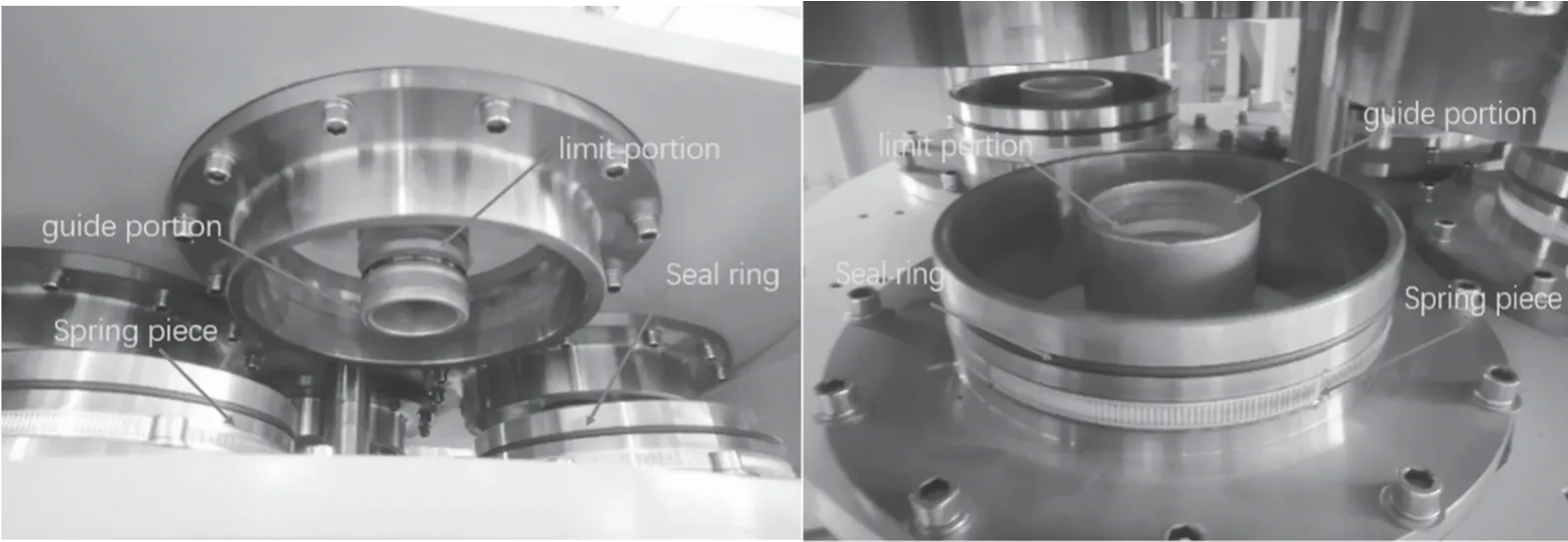
Figure 3.The entity of the coaxial switch.
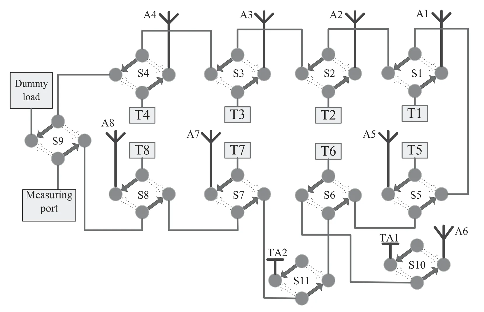
Figure 4.The schematic diagram of the coaxial switch network.
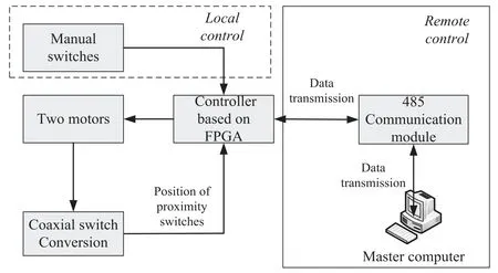
Figure 5.Control methods of the single coaxial switch.

Figure 6.The circuit board of the controller.
3.Control method of the coaxial switching system
Every coaxial switch has two control methods,which are local control and remote control.Four manual switches installed on one coaxial switch are used for the local control,when the communication of the coaxial switching network system is in interruption.The manual switches are able to control the two motors to complete switching action of the coaxial switch.Each coaxial switch has a controller based on FPGA.
The coaxial switch is remotely controlled when the communication is established.A suitable communication should be chosen to deal with the complicated electromagnetic environment of the ion cyclotron laboratory.In order to meet the performances and reduce the development difficulty,the reliable and common RS485 communication provides a solution.The FPGA which has a better performance was used as the control core in the controller.The RS 485 communication has a strong anti-interference ability between the master computer and the FPGA switch controller.Each coaxial switch controller has communication interfaces of RS485.The master computer controls the controller for operation through 485-communication modules.In addition to sending commands to the coaxial switch to reach the specified state if needed,the master computer also sends command to the controller to read the position information of the coaxial switch continuously.The controller obtains the position of the coaxial switches by detecting the signals of the four proximity switches.When the current position of the coaxial switch does not match the position specified by the command,the coaxial switch begins to convert moving.The switching process of the coaxial switch is mentioned in section 2.1.Then the master computer receives feedback information of the coaxial switch position in real-time and determines whether the switching is completed.The control methods of the single coaxial switch are shown in figure 5.
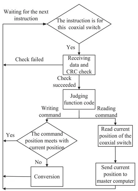
Figure 7.Data parsing process of the controller.
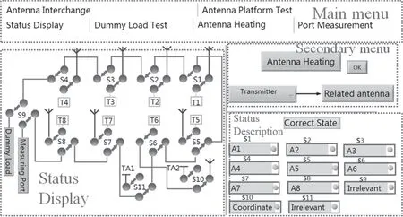
Figure 8.The interface of the master computer.
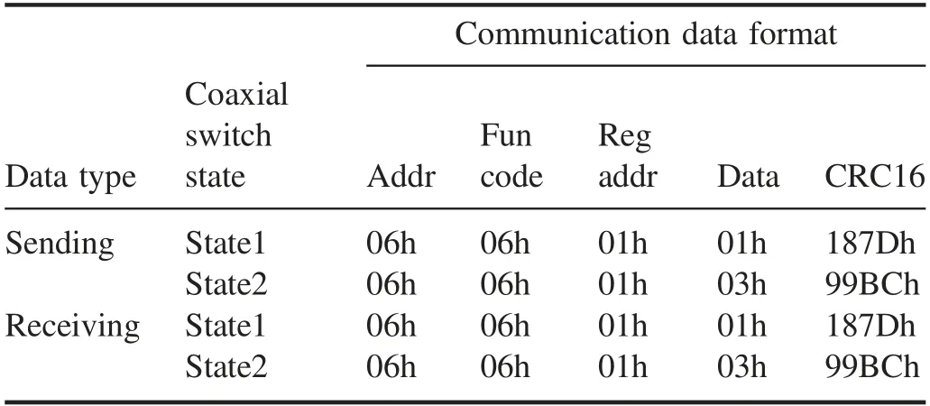
Table 1.Results of writing a command for controller 6 by master computer.
The controller based on FPGA is the main component and its circuit board is shown in figure 6 [11].Except the communication interface,the proximity switch interface,the two motor interfaces and the manual switch interface,there are also two VCC interfaces and two latching relay interfaces.The VCC interfaces are connected to 5 and 12 V switching power supplies respectively.Two latching relay interfaces act as interlocks for safety reason.When the coaxial switch is not ready for RF operation,the two latching relays stay‘open’,thereby preventing the transmitters to supply power.The latching relay interfaces ensure that the transmitter can supply power to the antenna or dummy load only when the coaxial switch is in corresponding position.Compared with the ordinary relay,the latching relay can still maintain the previous state after the power is turned off.
The communication interfaces of all controllers are connected to a sixteen port-hub through twisted pairs.The other end of the hub is connected to the master computer via a USB to RS485 serial cable.The communication between the master computer and the controller complies with the MODBUS protocol strictly.Thereby,the master computer can control the entire coaxial switching network in real-time.The following describes the communication process between the master computer and a single controller.Data parsing process of the controller is shown in figure 7.After receiving a frame of data from the 485-communication module,the controller determines whether the instruction is for this coaxial switch.If it is yes,the controller receives the data and checks by cyclic redundancy check module.Otherwise,the instruction is discarded.The data which is checked and succeeded will be judged by Judging function code.This code will read or write commands according to the judgment result.The writing command is of equal level with reading command.For reading command,it reads the current position of the coaxial switch and sends it to the master computer.For writing command,the controller determines whether command position of the coaxial switch meets with the current position acquired from the proximity switch.The coaxial switch will complete switching in case of non-compliance.The communication between the master computer and multiple controllers is similar to that of single communication.For this reason,the eleven controllers have been encoded with address numbers from 01 to 0B(Hexadecimal).The difference is that the master computer sends a series of data(11 frames which contain addresses from 01 to 0B)each time in multiple communication.
Program of the master computer which communicates with all the controllers is written by using National Instruments (NI)MODBUS module of LabVIEW[12].The master computer has two main features,which are reading module and writing module.The writing module contributes to send commands of the master computer to the eleven coaxial switches.Then the controller determines whether to operate according to the received data and the current state of the coaxial switch.The reading module sends a command to the controller so as to identify the current status of the coaxial switch.Meanwhile,it analyzes whether the status information accords with the target status.Finally,the result is displayed on the front panel.The interface of the master computer is shown in figure 8.The interface of the master computer consists of main menu,secondary menu,status display and status description.The main menu helps to select different functions of the coaxial switching network (heating,port measurement,dummy load test,antenna interchange and antenna platform test)as mentioned in section 2.
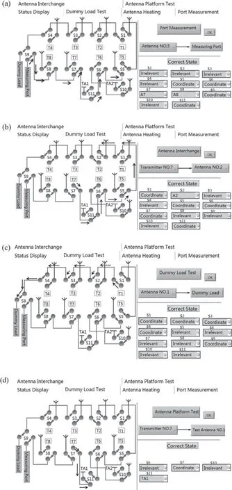
Figure 9.(a) Port measurement for A5,(b) antenna interchange for T7,(c) dummy load test for T1,(d) antenna platform test for T7.
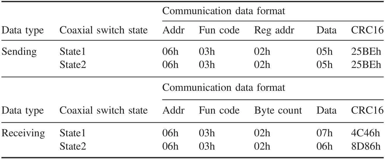
Table 2.Results of reading a command for controller 6 by master computer.
The secondary menu shows the function in real-time.The status display shows the status of the coaxial switching network.The status description indicates whether the task in the secondary menu is completed.
4.Communication tests and results
In order to verify whether the coaxial switching network achieves target status,the test is mainly divided into communication test of the single controller and the function test of the coaxial switching network.The communication test of the single controller consists of writing command test and reading command test.The writing command sends a specified state command to the coaxial switch.If the current state of the coaxial switch meets with the specified state,the coaxial switch will have no action.Otherwise,the coaxial switch will be switching.The reading command contributes to read the current state information of the coaxial switch.
One frame communication data format of the controller is regular in the MODBUS protocol.The format of writing and reading command is different.The following takes the communication test of controller No.6 as an example.The test of writing a command for controller 06 by the master computer is in table 1.Receiving writing date is exactly the same as the sending writing data in the same state.The ‘01h’ and ‘03h’which are in column‘Date’of the table 1 correspond the two states of the coaxial switch.The ‘CRC 16’ produced by a fixed algorithm also has two types.The test of reading a command for controller 06 by the master computer is in table 2.The sending data is the same in the two states.The‘07h’ and ‘06h’,which are in column ‘Date’ of the table 2,indicate that the coaxial switch is in different positions.The test indicates that the master computer can identify reading or writing command to the controller of the coaxial switch normally.
The function test of the coaxial switching network is to verify its main functions.After receiving the command from the master computer,all the coaxial switches will reach the specified state a few seconds later.We have selected some coaxial switches to test the specific function as shown in figure 9.The item tested is port measurement for A5,antenna interchange for T7,dummy load test for T1 and antenna platform test for T7.The specific test content is shown in secondary menu region.In status display region,the coordination state of related coaxial switches is shown and the arrow indicates the microwave transmission path.In status description region,it shows the correct state of all the coaxial switches.The ‘Irrelevant’ means that this coaxial switch is unconcerned with this test.The test results show that all coaxial switches complete switching process smoothly under the control of the control system.
5.Summary
This paper introduces the coaxial switching system of ICRH in EAST and its control method.A single coaxial switch can be switched between two states,and eleven coaxial switches form the whole coaxial switching network.The coaxial switch network can form a required state to meet the needs of the experiment.There are two ways to control the coaxial switching network: local control and remote control.In remote control,the master computer software is written in LabVIEW and the controller uses FPGA as the main control chip to realize 485 communication through the serial port.The controller identifies reading or writing command to the coaxial switches by setting different controller addresses.The interface of master computer contributes to control and monitor the eleven coaxial switches to meet different experimental requirements in real-time.The experimental tests verify the operation of the coaxial switching system.By introducing RS485 communication,the electromagnetic noise problem is improved.The system has been used in the ion cyclotron laboratory of EAST to serve the EAST experiment.
Acknowledgments
This work was supported by National Natural Science Foundation of China (Nos.11575237,11775258),National Key Research and Development Program (Nos.2016YFA0400600 and 2016YFA0400601) and China Fusion Engineering Experimental Reactor General Integration and Engineering Design (No.2017YFE0300503).
猜你喜歡
當代作家(2023年5期)2023-07-10 22:13:48
名家名作(2022年16期)2022-11-10 14:52:35
金橋(2022年9期)2022-09-20 05:50:30
金橋(2022年5期)2022-08-24 01:41:16
金橋(2022年8期)2022-08-24 01:34:46
金橋(2022年6期)2022-06-20 01:35:40
鐵道通信信號(2020年3期)2020-09-21 09:13:06
消費導刊(2020年27期)2020-07-13 09:34:46
金橋(2020年8期)2020-05-22 06:22:54
金橋(2018年10期)2018-10-09 07:27:44
 Plasma Science and Technology2020年4期
- Plasma Science and Technology的其它文章
- Preliminary design of high power magnet converter for CRAFT
- Fast radial scanning probe system on KTX
- Estimation of plasma density perturbation from dusty plasma injection by laser irradiation on tungsten target in DiPS
- Investigation on plasma characteristics in a laser ablation pulsed plasma thruster by optical emission spectroscopy
- A two-dimensional air streamer discharge model based on the improved Helmholtz equation at low temperature and sub-atmospheric pressure
- Mode transition induced by gas pressure in dusty acetylene microdischarges: twodimensional simulation