Polyaxial strength criterion and closed-form solution for squeezing rock conditions
Rupesh Kumar Verma, Sarvesh Chandra
Department of Civil Engineering, Indian Institute of Technology Kanpur, Kanpur, 208016, India
Abstract In this paper,a nonlinear strength criterion is proposed using the average of intermediate(2)and minor(3) principal stresses in place of 3 in Ramamurthy (1994)’s strength criterion. The proposed criterion has the main advantages of negligible variation of strength parameters with confining stress and ability to link with conventional strength parameters. Additionally, a new closed-form solution based on the proposed criterion is derived and validated for Chhibro Khodri tunnel. Further, analytical solutions including Singh’s elastoplastic theory, Scussel’s approach, and closed-form solutions based on conventional and modified Ramamurthy(2007)criteria are compared with the results of proposed approach.It is shown that the in situ squeezing pressure predictions made by the proposed approach are more accurate. Also, a parametric study of the present analytical solution is carried out, which displays explicit dependency of tunnel stability on internal support pressure and tunnel depth. The influence of tunnel geometry is observed to be dependent on the applied support pressure.
2020 Institute of Rock and Soil Mechanics, Chinese Academy of Sciences. Production and hosting by Elsevier B.V. This is an open access article under the CC BY-NC-ND license (http://creativecommons.org/licenses/by-nc-nd/4.0/).
Keywords:Intermediate principal stress Squeezing pressure Closed-form solution Polyaxial strength criterion
1. Introduction
Underground tunnel construction generally faces incompetent rock masses where squeezing of rock is a common problem, for example the tunnels in Himalayan region in India. Under such conditions,the three principal stresses play crucial role in defining complex in situ stress conditions, which significantly differ from conventional triaxial stress state.This highlights the importance of failure criterion’s competency to capture the behavior of geomaterial under any given in situ conditions. A basic strength criterion for geological materials was proposed by Mohr and Coulomb(Labuz and Zang, 2012), which suggested the linear variation of strength with confining stress. Simplistic nature and better material behavior predictability, especially in case of soil, make this criterion widely popular among research community. However, it lacks applicability for rocks due to its linearity,which overestimates the material’s tensile strength.
Kármán (1912) studied the influence of confining stress on the strength of intact rock and depicted the nonlinear strength variation with downward curvature restraining the overestimation of material’s tensile strength. This approach was later validated (e.g.Griffith,1924; Murrell, 1964; Walsh and Brace, 1964; Mogi,1965;1972; 2006; Hoshino et al., 1972; Hoek and Brown, 1980;Bieniawski, 1990; Ramamurthy, 1994; 2001; 2007; Hoek and Diederichs, 2006; Hoek and Marinos, 2007; Rafiai, 2011; Zuo et al., 2015). However, a majority of these criteria are based on triaxial test data, which ignore the effect of intermediate principal stress(2)especially in deep underground conditions.Nadai(1963)developed constitutive models incorporating the influence of2but had no experimental data for support. Mogi (1972) conducted laboratory polyaxial tests to highlight the role of2and proposed an empirical failure criterion, which was modified by Al-Ajmi and Zimmerman (2006), Mogi (2006), and Feng et al. (2016). This empirical failure criterion does take into account the influence of2with sufficient experimental data but faces difficulty in linking with the conventional strength parameters such as cohesion (c) and friction angle ().
Singh et al. (1998) proposed a semi-empirical approach by modifying the MohreCoulomb strength criterion to incorporate the effect of2as follows:

Based on this criterion, Singh and Goel (2006) developed an elastoplastic theoretical approach to compute stress distribution in broken zone around a deep underground circular opening:

The radial stress at the interface of elastic and plastic zones,i.e.critical stress(Pcr), can be obtained as follows:

Results obtained by the above theory agreed with field observations under severe squeezing conditions, but use of different constitutive models in elastic and plastic zones along with linearity of failure envelop still restricts its wide applications. Later, Scussel and Chandra (2013) proposed the following ‘equivalent strength parameters’in MohreCoulomb criterion to incorporate the effect of


To overcome this, Ramamurthy (1994) suggested the following criterion with nonlinear strength behavior which has extensive applications in a wide range of rock types:


Later, Ramamurthy (2007) suggested a modified strength criterion to incorporate the effect of2:

This paper presents an alternative approach to incorporate the effect of2by proposing simple modification in the conventional Ramamurthy (1994) criterion. The proposed criterion is validated with available experimental data of various rock types under different loading conditions, i.e. triaxial and non-triaxial. Then a closed-form solution based on the proposed criterion is derived to analyze deep underground in situ stress conditions. Additionally,closed-form solution based on the modified Ramamurthy criterion(i.e.Eq.(10))is also presented.Comparison between the above two analytical solutions with the conventional Ramamurthy criterion(i.e. Eq. (8)) based solution highlights the significance of2in overall stress state predictions. Further, the proposed approach is used in the Chhibro Khodri tunnel, India, where in situ squeezing pressure predictions made by the derived analytical solutions are compared with field observations. Also, predictions of other approaches including Singh’s elastoplastic theory (Singh and Goel,2006), Scussel’s criterion (Scussel and Chandra, 2013), and modified (i.e. Eq. (10)) and conventional (i.e. Eq. (8)) Ramamurthy criteria based solutions are analyzed to ascertain the efficiency of proposed approach. Finally, a detailed parametric study of the proposed criterion based solution is presented.
2. Proposed strength criterion
The intermediate principal stress2is important in determining rock mass strength around deep underground openings. Many failure criteria have been suggested, but their applications are limited due to the precision problem in material behavior prediction, especially under high confining stress. Therefore, this paper suggests the following yield criterion obtained by introducingm23factor in place of3in the conventional Ramamurthy (1994)strength criterion:

Further, the validity of the proposed criterion is investigated using compression test data of four different rock types,i.e.Yuubari shale, Solenhofen limestone, Shirahama sandstone and Dunham dolomite (Colmenares and Zoback, 2002). Dunham dolomite and Solenhofen limestone have comparatively higher sensitivity to2variation. These experiments were conducted in both triaxial (i.e.2z3) and non-triaxial (i.e.2>3) stress conditions. For polyaxial test data validation, the magnitude of2is varied from minimum confining stress(i.e.w3)to maximum deviatoric stress(i.e.w1) while keeping the magnitudes of other principal stress components constant. Fig. 1 presents the overall results of above validation and comparison in normalized form, i.e. (13)/23versusci=23;where triaxial and polyaxial experimental data are distinctly highlighted.
For Yuubari shale and Solenhofen limestone as shown in Fig.1a and b, respectively, strength parameters obtained at lower confinements (i.e. 25 MPa and 20 MPa) are used to predict the rock material behaviors at higher confinements. Whereas in case of Shirahama sandstone and Dunham dolomite, the corresponding parameters obtained at confining stresses of 8 MPa and 45 MPa are used to predict the rock material behaviors at wider range of confining stresses (Fig. 1c and d). Overall, the proposed criterion acquires a common envelope to predict the material strength in both polyaxial and triaxial experimental conditions.Its predictions for behaviors of different rocks are in good agreement with experimental observations. Thus, it ascertains the validity of the proposed criterion for different rock types under diverse loading ranges including polyaxial stress state which is quite common in deep underground openings.
3. Closed-form solution for circular opening using the proposed strength criterion
This section presents the derivation of proposed strength criterion based closed-form solution to analyze the stress conditions around a circular tunnel opening with radiusri. For simplicity, the surrounding rock mass is assumed to be intact, isotropic and homogeneous in nature. The plastic zone formed around the tunnel opening during excavation is the zone of broken rock material, i.e.broken zone. The tunnel is located at depthhiand subjected to hydrostatic stress (P0) field (Brown et al., 1983), i.e. hydrostatic pressure equal to the overburden stress (i.e. plane strain conditions),as shown in Fig.2,wherePiis the internal support pressure.
The geometrical symmetry of the circular tunnel opening and in situ stress conditions enable the consideration of radial (r) and tangential()stresses to be the major(1)and minor(3)principal stresses acting on the tunnel periphery. Thus, it results in a plane strain condition with the following equilibrium equation applicable for both elastic and plastic zones around the circular opening:

Additionally, the following boundary conditions are used to obtain the expressions for stresses and plastic zone thickness around the tunnel periphery:
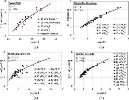
Fig.1. Validation of proposed criterion.
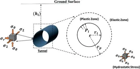
Fig. 2. Brief tunnel layout.

wherePcris the critical internal pressure below which the rock material around the opening starts losing strength to undergo plastic deformation. After satisfying the equilibrium and compatibility equations along with the above boundary conditions, the following expressions for radial (r) and tangential () stress distributions in the elastic zone can be obtained:

Using Eqs.(14)and(15)at the interface of the elastic and plastic zones (i.e.rrp) along with the proposed strength criterion (Eq.(11))and corresponding boundary conditions given in Eq.(13),the following expression can be obtained:

This expression can be used to computePcr, which implicitly indicates the rock material strength for any given in situ stress conditions. Further, using the equilibrium equation and suggested failure criterion in the plastic zone,the following expression can be obtained:

For the given in situ conditions, it is reasonable to expect the formation of circular plastic zone around the tunnel opening after the material’s yield strength is exceeded by resultant in situ stresses. Therefore, the plastic zone radius (rp) can be obtained by applying the interface boundary condition (Eq. (13)) to Eq. (17):

Further rearrangement of Eq. (17) results in the following expression for computing the radial stress distribution in the plastic zone:

The tangential stress in the plastic zone can be computed by using Eqs. (19) and (11) as follows:

In the above formulation,effect of earthquake is not considered due to its negligible influence on deep underground structures.
4. Closed-form solution for circular opening using modified Ramamurthy strength criterion
This section presents the formulation of closed-form solution based on the modified Ramamurthy strength criterion,i.e.Eq.(10).Here, the expression for the critical stress can be obtained by considering elastic stress state (i.e. Eqs. (14) and (15)) along with the elastoplastic interface boundary conditions and corresponding strength criterion (Verma and Chandra, 2016):

The plastic radius (rp) is obtained using the equilibrium conditions along with the plastic zone boundary conditions as follows:

The radial and tangential stresses in the plastic zone are obtained considering the equilibrium conditions in the plastic zone using the modified Ramamurthy criterion as follows:

Here,the expressions for the stresses in the elastic zone are the same as those derived in Eqs. (14) and (15). Similarly, the closedform solution based on the conventional Ramamurthy criterion can also be obtained (Ramamurthy, 2007); however, it does not incorporate the influence of2.
5. Comparison of closed-form solutions based on the proposed, conventional and modified Ramamurthy criteria
This section presents the comparison of the closed-form solutions based on the proposed method (Eq. (11), approach-1),modified Ramamurthy criterion (Eq. (10), approach-2), and conventional Ramamurthy criterion(Eq.(8),approach-3).Comparison of the latter with the other two approaches will highlight the influence of2in overall predictions. Additionally, two cases of material type choice are considered:elastic-perfectly plastic(p,r,cp,andcr,wherecpis the peak cohesion)and strain-oftening.The input parameters are presented in Table 1.
Resultant radial and tangential stresses obtained from above three solutions are normalized with in situ hydrostatic stress,i.e.r/P0and/P0. Variations of these stresses with normalized radial distance (r/ri) for the above two cases are presented in Fig. 3.
For the elastic-perfectly plastic case in Fig. 3a, the tangential stresses computed by all three approaches in the plastic zone increase continuously from the minimum at the opening radius(ri)to the peak at the interface of elastic and plastic zones. Thereafter,they gradually decrease to in situ hydrostatic stress condition at normalized radial distance of 6.5 approximately. Comparing the peaks, approach-1 results in the maximum normalized tangential stress of 1.51, which is 1.34% and 4.9% higher than those of approach-2 and approach-3.
On the other hand, the radial stresses obtained from all three solutions demonstrate continuous increase from the minimum at opening radius(rri)to the maximum of in situ hydrostatic stress obtained at similar normalized radial distance of 6.5 approximately.Overall, approach-3 results in comparatively lower radial stress magnitude. However, the radial stress predictions of all three approaches have a common starting point which physically signifies the applied support pressure (Pi) in horizontal direction at tunnel periphery.By comparing the plastic zone extent(i.e.radial distance of tangential stress peak from tunnel opening),approach-1 results in normalized plastic radius(i.e.rp/ri)of 1.49 which is 4.7%and 22%lower than that of approach-2 and approach-3, respectively.
Fig. 3b presents the strain-softening scenario which is widely used to represent rock-like brittle material. This modeling characteristic incorporates the degrading strength characteristics via residual parameters as shown in Table 1.Researchers also introduced damage parameters to investigate material degradation mechanisms in such modeling approaches (Jing and Stephansson, 2007;Zhao et al., 2014; Ji et al., 2018). All these modeling techniques provide an ease to replicate the realistic material characteristics theoretically.However,to demonstrate the presented formulations’functioning, this paper presents a simple strain-softening model where material acquires residual values immediately after reaching its elastic limit.These residual material parameters(i.e.Table 1)are the conceptual representation of damaged material. The sudden jump in the normalized radial and tangential stress magnitudes immediately at the interface of plastic and elastic zones(i.e.rrp)is the effect of acquiring residual strength parameters of degraded material immediately after the elastic zone. These additional parameters (i.e. residual) could provide an ease for better calibration to improve the rock material behavior prediction. However, the magnitudes ofPiandrpare not affected by the choice of material types. Apart from this, the general trend of stress distributions in radial and tangential directions is similar in both cases.

Table 1Input parameters.
Overall, approach-3 predicts lower resultant stresses with higher plastic zone thickness comparatively. It shows that neglecting the influence of2results in serious underestimation of rock material strength estimation around underground opening(Handin et al., 1967; Cai, 2008). On the contrary, the proposed criterion based solution predicts relatively higher strength while taking the effect of2into account. This formulation requires further validation which is presented with the Chhibro Khodri tunnel case in Section 6.
6. Squeezing pressure prediction:Chhibro Khodri tunnel case
Chhibro Khodri tunnel is part of an Indian hydroelectric project on Yamuna River.The tunnel is approximately 5.6 km long between Chhibro and Khodri with circular cross-section of 7.5 m diameter.This project was popular for severe in situ squeezing conditions which did cause serious problems in tunnel construction during excavation stage. Consequently, many researchers took this opportunity to observe the real-time squeezing behavior of surrounding rock mass. Jethwa et al. (1980) determined the plastic radius (rp) and radial squeezing pressurePsiin the horizontal direction around tunnel section with geological formation of red shales and black clays. In addition to geological mapping, mineralogical, physical and shear resistance characteristics were also determined(e.g.Jain et al.,1975;Jethwa et al.,1980;Dwivedi et al.,2014a). Details of tunnel layout, geological mapping and geotechnical characterization of rock mass around tunnel periphery are presented in Fig. 4. A summary of the important geotechnical characteristics along with the in situ stress (P0) and squeezing pressure observations at the tunnel sections in different rock types is presented in Table 2.
The rock mass around the tunnel opening is substantially isotropic and homogenous in nature (Scussel, 2012). Thus, these observations are used in this study to validate the applicability of proposed criterion based closed-form solution. Additionally,Singh’s elastoplastic solution (i.e. Eqs. (1)e(4), approach-4) and Scussel’s solution(Eqs.(5)e(7),approach-5)are applied along with the previous three approaches to compare the reliability of proposed criterion based solution.
Further,to predict the squeezing pressure,uniaxial compressive strength (ci) of surrounding rock material is required, which is unavailable owing to insufficient information. Consequently,different approaches use various expressions correlatingciwith other strength parameters. Approach-4 (Singh and Goel, 2006)adopted the following expression forcicomputation:

While approach-5 (Scussel and Chandra, 2014) along with the first three approaches used the following standard MohreCoulomb expression:

In the absence of residual strength parameters,rock material is assumed to be elastic-perfectly plastic in nature.This assumption is reasonable in terms ofPiandrpcomputations which remain unaffected by the material choice as shown in Fig.3.Thus,the strength parameters for the first three approaches are obtained from Eq.(9)(i.e.iz 2.8 and aiz 0.5) where the tensile strength of rock material takes one-tenth of the compressive strength(Singh and Goel,2006). In principle, all required strength parameters in the proposed approach are derived from MohreCoulomb parameters(i.e.cand).
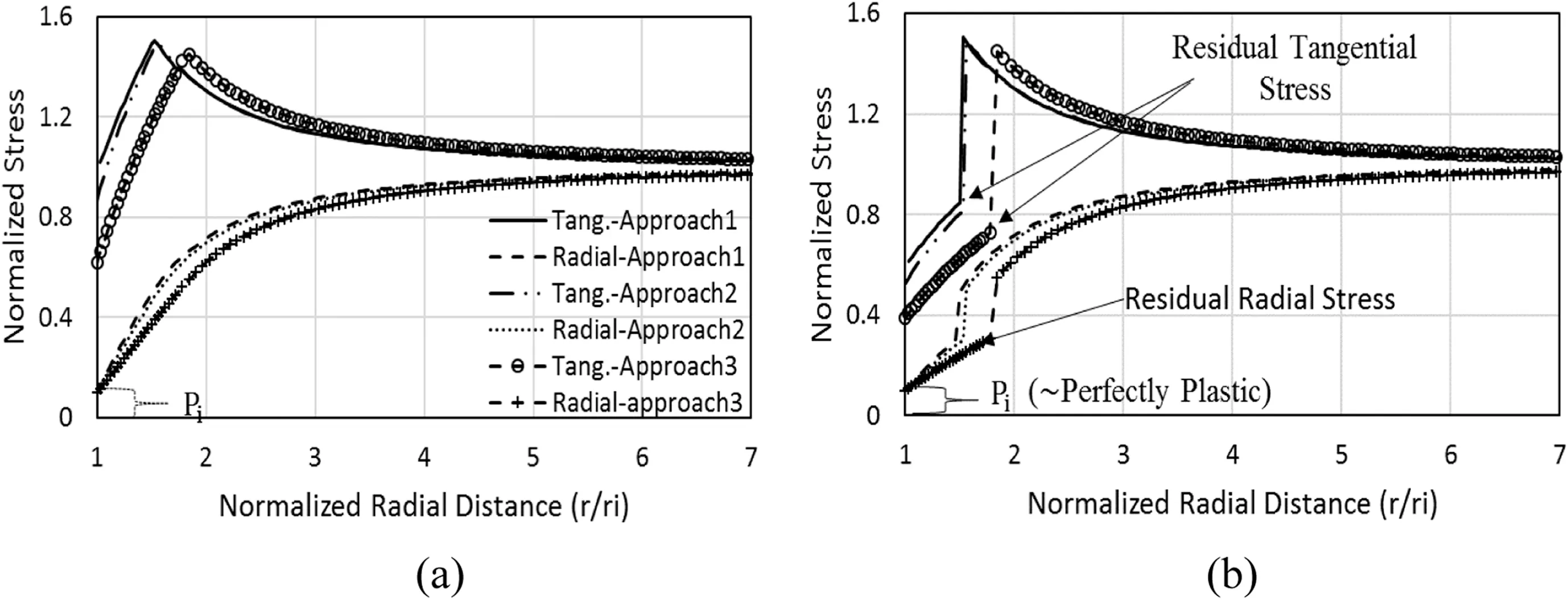
Fig. 3. Comparison of stresses for (a) elastic-perfectly plastic and (b) strain softening cases.
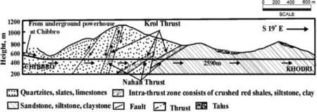
Fig. 4. Geological mapping of Chibbro Khodri tunnel (Jethwa et al.,1980).

Table 2Geometrical and geotechnical characteristics of rock mass (Scussel and Chandra,2014).
Furthermore, plane strain conditions across the tunnel periphery are taken into account where the magnitude of2remains constant(wP0)along the tunnel direction.Additionally,approach-1 uses Eq.(18)while approach-2 uses Eq.(22)forPsipredictions.For approach-3, the following expression is used forPsicalculation(Ramamurthy, 2007):

A brief summary of squeezing pressure predictions by all the above approaches is presented in Table 3. From Table 3, one can observe thatPsipredictions made by approach-1 show the minimum average variance of 49% from actual observations, whereas approach-3 exhibits the maximum variance. This shows the importance of2and reliability of proposed criterion based solution in rock mass behavior prediction.It also indicates the efficiency of proposed approach’s linking with widely used conventional strength parameters. Finally, majorities of predictions in above solutions forecast higher magnitudes ofPsiin comparison to actual observation. The reason behind this could be the delay in installation of support and sensors to record pressure/displacement after excavation.Practically,this time lag is difficult to be estimated.
7. Parametric study of proposed criterion based closed-form solution
As per Eqs.(19)and(20),factors such as rock material strength,in situ stress conditions, tunnel opening size (ri), thickness of broken zone (i.e. plastic zone), support pressure (Pi) and radial distance from the tunnel center (r) predominantly control the resultant stress conditions. Among all the above factors, opening size and support pressure are the parameters which can be altered.In addition,if the location of tunnel can be changed,then the effect of in situ hydrostatic stress(P0) due to the overburden can also be controlled. A parametric study is conducted to delineate the effect of above controlling factors on overall tunnel stability. The input parameters used in this study are taken from Table 1. For simplification, material is assumed to be elastic-perfectly plastic while effects of construction method,excavation rate and time to provide support pressure have been ignored.
7.1. Effect of support pressure on extent of broken zone
Broken zone formation around the tunnel periphery takes place when the support pressure (Pi) inside underground opening reduces to be below the critical stress(Pcr).Therefore,it is impossible to restrain the plastic deformation forming broken zone during tunnel excavation process.However,its thickness can be controlled by applying appropriatePi.To quantify the effect ofPion the extent of broken zone, Eq. (18) is used to determine the extent of broken zone,which is considered equivalent to the plastic zone radius(rp).Fig.5 represents the variation of broken zone extent(wrp)around the tunnel opening withPi.

Table 3Summary of squeezing pressure predictions.
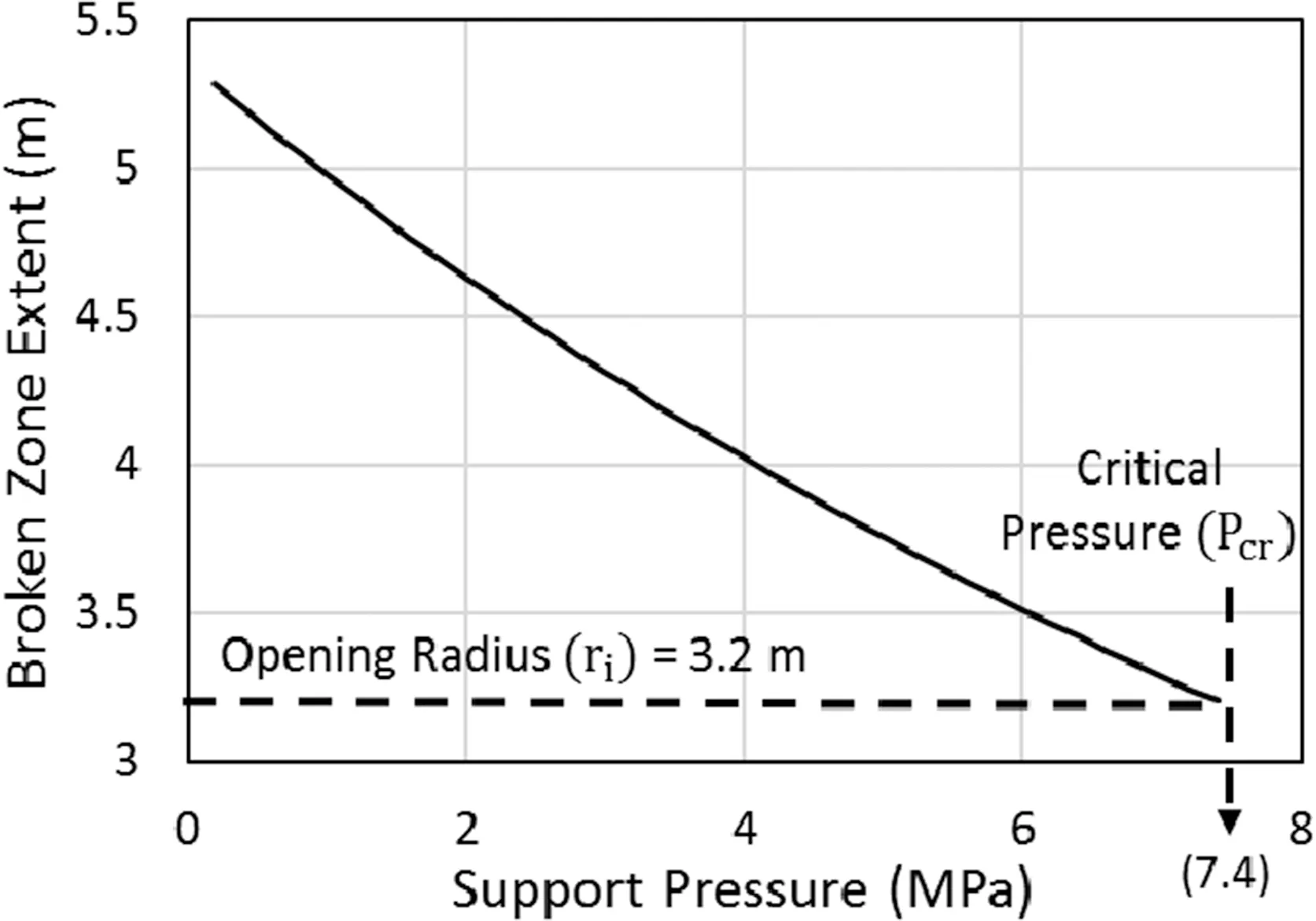
Fig. 5. Variation of broken zone extent with support pressure.
For support pressure(Pi)of 1 MPa in Fig.5,the plastic radius(rp)is observed to be 4.97 m.It further reduces to 3.28 m atPi7 MPa.This overall trend ofrpreduction withPiincrease is nonlinear,which further reduces to 3.2 m (ztunnel radius) atPi7.4 MPa,indicating the disappearance of the entire inelastic zone.Thus,this support pressure is critical(wPcr),and the magnitude is dependent on the material characteristics and confining stress, and independent of the applied support pressure or tunnel geometry. This explains the common observations of higher damage in weak rock mass under deep underground as compared to rock mass at shallower depth (Singh and Goel, 2006).
7.2. Effect of opening radius on broken zone thickness
Apart from the internal support pressure(Pi), tunnel geometry,i.e. opening radius (ri), also influences the broken zone thickness(tp).Fig.6a presents the variation oftpwithPifor differentrivalues.It can be observed that the opening with radius of 3.2 m undergoes reduction of 2.08 m intpwith an overall increment of 7.2 MPa inPi.This reduction intpincreases to more than 300% for an opening radius of 10 m. It indicates that for any givenPiincrement,improvement in surrounding rock stability is significantly higher in case of tunnels with larger opening dimensions (Goel et al.,1996).In addition, these results also provide an ease to optimize the tunnel opening radius and the support pressure as the controlling input parameters to acquire required tunnel stability.
The above inference can be further verified in Fig. 6b which shows the variation oftpwith the opening radius under differentPiconditions. Here,tpincreases with the increase in opening radius from 0.2 m to 7.5 m for the givenPi.However,slopes of these plots show reduction of 51% with variation inPifrom 1.52 MPa to the critical pressure. This indicates that increase inPidiminishes the influence of tunnel opening dimension on the overall stability. In fact, for the case of critical support pressure, the opening radius factor becomes almost irrelevant. It shows that the effect of opening geometry is implicitly linked toPiand surrounding rock characteristics(in terms ofPcr).This observation matches the notion of negligible influence of circular tunnel opening radii on the overall deformation property under the application of required tunnel support pressure(Dwivedi et al., 2014b).
7.3. Effect of support pressure on resultant stress conditions
For a given tunnel opening of 3.2 m radius,radial and tangential stress distribution plots in normalized forms(i.e.r/P0and/P0)at different values ofPi(1.52 MPa, 3 MPa, 5 MPa and 7.4 MPa) using Eqs. (14) and (15) in the elastic zone and Eqs. (19) and (20) in the plastic zone are presented in Fig. 7.
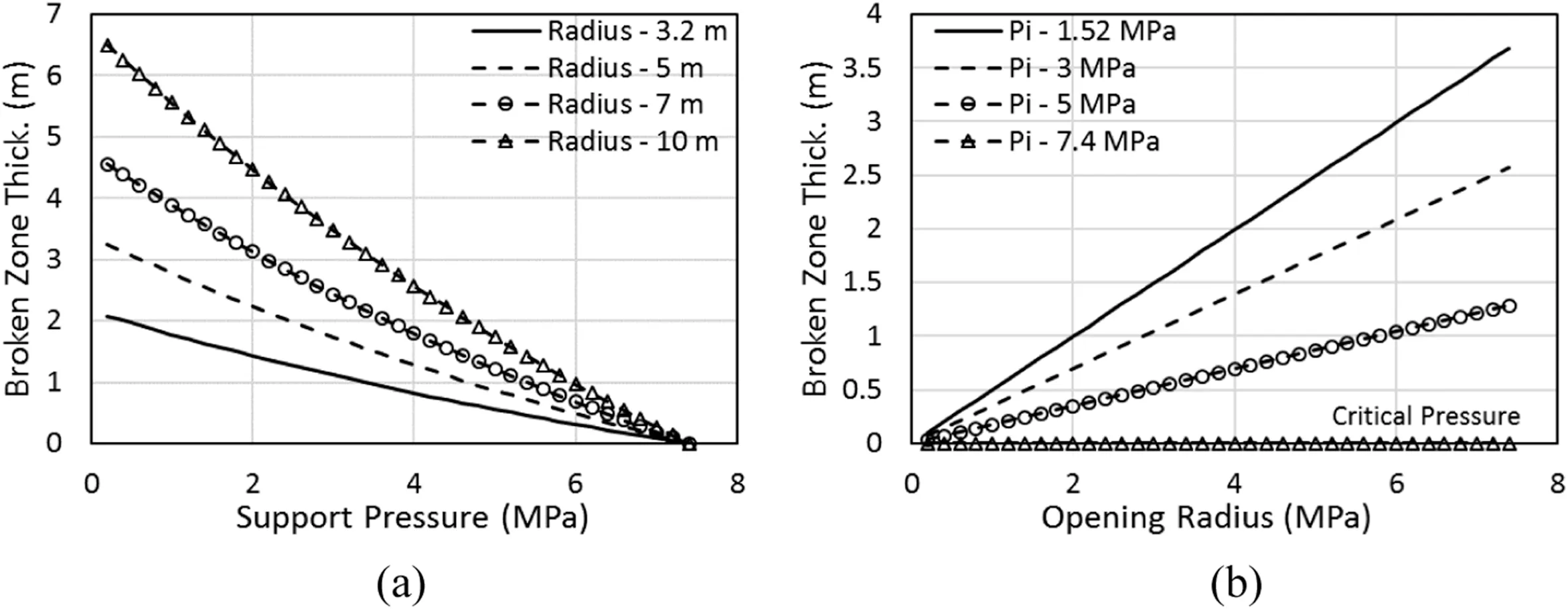
Fig. 6. Variation of broken zone thickness with (a) support pressure and (b) opening radius.
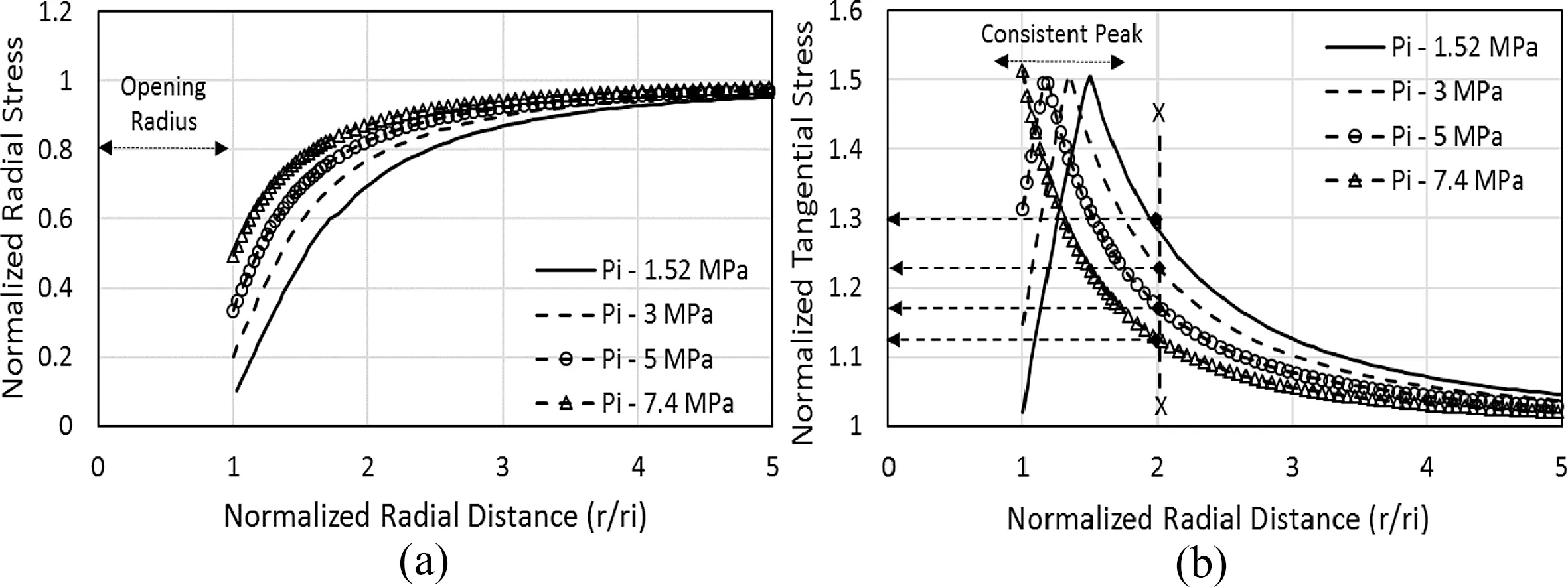
Fig. 7. Stress variations with support pressure.
In Fig. 7a, the normalized radial stress increases from 0.1 at tunnel opening to 0.49 with increase inPifrom 1.52 MPa to 7.4 MPa(wPcr). The difference in radial stress magnitude is pronounced near the opening indicating significant influence of appliedPion radial stresses at tunnel periphery.The difference due to variance inPidecreases with increase in radial distance from the center of the opening and becomes zero with all radial stresses approaching in situ hydrostatic stress(i.e.r/P0)at a normalized radial distance of 5 approximately.Therefore,it can be inferred that the difference between the in situ hydrostatic pressure(P0)and radial stress at the opening periphery (r) decreases with increase in appliedPi.Consequently, it reduces the magnitude of unbalanced stresses around underground opening causing reduction intp, hence improvement in tunnel stability.
Further, Fig. 7b shows that the variations inPihave similar effects on the tangential stress distribution where the magnitude of normalized tangential stress at tunnel opening (i.e.r/ri1) increases from 1.02 to 1.51 with increase inPifrom 1.52 MPa to 7.4 MPa. In addition, all four plots of normalized tangential stress distribution attain roughly the same peak of 1.508 at different normalized radial distances.This variance in radial distance of peak stresses indicates the variation oftpwithPi. This can be crossverified by analyzing the radial distance of normalized tangential stress curve’s peak for the case of critical support pressure (i.e.Pcr7.4 MPa) which occurs at the normalized radial distance of 1 indicating zerotp. Therefore, peaks of these plots in Fig. 7b can be considered as the beginning of elastic zone where normalized tangential stress undergoes reduction with increase in radial distance from opening center.The tangential stresses reduce to in situ hydrostatic stress magnitude at a normalized radial distance of 5 approximately which is similar to the radial stress distribution(Fig.7a).Further,by comparing the tangential stress magnitudes in all four cases at fixed radial distance from tunnel center, one can observe that increase inPiresults in considerable decrease in the tangential stress in the elastic zone.
Overall,the above plots clearly indicate that increase in appliedPidecreases the differences between in situ hydrostatic and opening periphery stresses, which eventually restrainstpand provides better tunnel stability. These results are in accordance with the observations available in the literature supporting the validity of the presented analytical solution (Goel et al., 1996;Dwivedi et al., 2014b; Chen et al.,2018).
7.4. Variation in critical pressure and broken zone thickness with tunnel depth
Depth of tunnel (hi) beneath the ground surface explicitly controls the confining stress affecting the critical pressure (Pcr) and broken zone thickness(tp)around underground opening,as shown in Fig. 8.
As per the presented formulation,Pcrof any given rock mass for a fixed opening dimensions (i.e.ri3.2 m) andPi(w1.52 MPa)increases linearly with increase inhi.It implies that tunnels located at deeper depth require higherPito ensure zero thickness of broken zone. This can be further verified by tracing the variation oftpexplicitly withhifor any given opening andPi. This variation is nonlinear in nature,indicating increasedtpwithhiat higher depth.
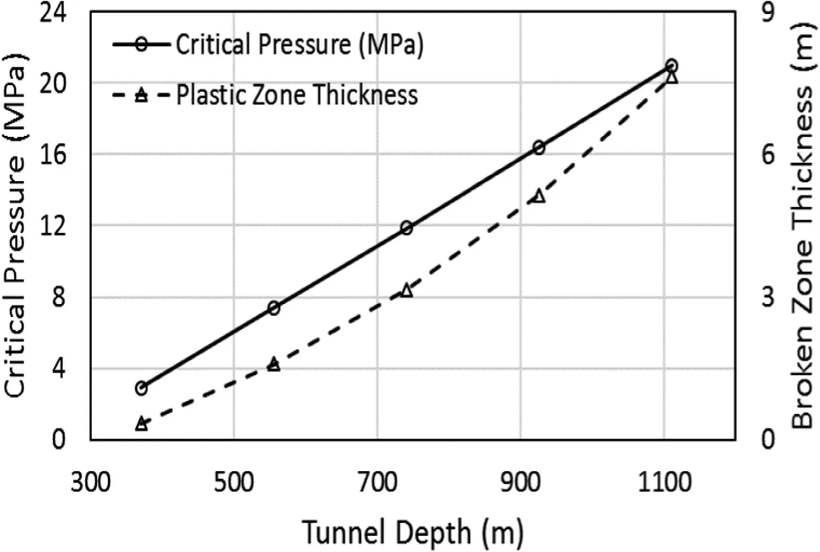
Fig. 8. Variations of critical pressure and broken zone thickness with tunnel depth.
8. Conclusions
This paper proposed a polyaxial strength criterion which has been validated with experimental data of different rock types under a wide range of loading conditions. Negligible variation of strength parameters with confining stress and convenience to link with other conventional criteria are its key benefits. Further, a closed-form solution based on the proposed criterion has been derived to analyze the stress conditions around underground openings. This analytical solution has been used to evaluate the weak rock mass in Chhibro Khodri tunnel case. It shows higher accuracy in squeezing pressure predictions by the proposed approach in comparison with other available ones.
Additionally, a detailed parametric study of the presented analytical solution has been conducted which shows decrease in broken zone thickness around opening periphery with increased support pressure. This tunnel stability improvement can also be achieved by optimizing the opening radius; however, its influence becomes negligible at critical support pressure. Finally, this study shows that increase in tunnel depth increases the magnitude of critical support requirement and corresponding broken zone thickness around tunnel periphery. This overall research work highlights the simplicity of analytical solution’s formulation and its applications. The presented formulation can be extended to numerical modeling approaches to further explore various aspects of deep underground opening stability.
Declaration of Competing Interest
We wish to confirm that there is no known conflict of interest associated with this publication and there has been no significant financial support for this work that could have influenced its outcome.
Acknowledgments
The authors are grateful to Dr. Bhawani Singh and Dr. Dario Scussel for sharing the information regarding essential data in their published articles which have been helpful in the present publication.
 Journal of Rock Mechanics and Geotechnical Engineering2020年3期
- Journal of Rock Mechanics and Geotechnical Engineering的其它文章
- Crack initiation of granite under uniaxial compression tests: A comparison study
- Reliability analysis of slopes considering spatial variability of soil properties based on efficiently identified representative slip surfaces
- Critical state model for structured soil
- Coupled hydro-mechanical analysis of expansive soils: Parametric identification and calibration
- A modified soil water content measurement technique using actively heated fiber optic sensor
- Benchmark solutions of large-strain cavity contraction for deep tunnel convergence in geomaterials
