Influence of Experimental Conditions on DDT Characteristics of Powdery Emulsion Explosive
DUAN Bao-fu, SUN Ke-bin, SHEN Shi-zhan, HOU Wei, GU Li
(1.Key Laboratory of Civil Engineering Disaster Prevention and Mitigation, Shandong University of Science and Technology,Qingdao 266590, China; 2.College of Civil Engineering and Architecture, Shandong University of Science and Technology, Qingdao 266590, China)
Abstract:To study the stability and safety of powdery emulsion explosives in the process of production, transportation, storage and use, the mechanism of Deflagration to Detonation Transition (DDT) was analyzed. Powdery emulsion explosive samples with average particle sizes of 92, 130 and 150μm were selected as the research objects. Experimental methods were designed to conduct DDT experiments on different loading densities’ beds by using a DDT tube sealing device. The results show that only the velocity signal of the detonation stage is detected when the fiber optic probe is located on the inner wall of the DDT tube. When the fiber optic probe is located at the axis of the explosive bed, the relative complete combustion and detonation velocity signals of the explosive bed are obtained. When the DDT tube is placed horizontally, the DDT phenomenon occurs in all the beds with the loading density of 0.67-0.89g/cm3. When the loading density exceeds this range, the combustion of the beds is easily stopped, and the DDT phenomenon is difficult to occur. When the DDT tube is placed vertically or obliquely, no detonation occurs in the explosive bed with different loading densities, and combustion that keeping away from the ignition head is not propagated. It indicats that powdery emulsion explosives cannot burn by themselves without sufficient external energy support. The position of probes and the placement types of DDT tubes directly affects the results of DDT experiments.
Keywords:powdery emulsion explosive; combustion to detonation; DDT tube; combustion characteristics
Introduction
Deflagration to Detonation Transition (DDT) is a common phenomenon when various energy-containing materials (propellants, detonators, etc.) are deflagrated[1]. According to the different applications of explosives, there are different requirements for this DDT phenomenon. From the application effect, it required that industrial explosives can easily change from deflagration to detonation. In terms of the safety of production, transportation and storage for the explosives, it is not desirable to occur the transition from combustion to detonation. Therefore, it is necessary and extremely important for people to understand and study the DDT process of explosives, so as to provide theoretical guidance for the production, transportation, storage and use of explosives.
Foreign studies on explosives DDT began in the 1940s. After several decades, relatively successful experiences have been accumulated[2-3]. Chinese scholars started the study on DDT late, nearly half a century later than foreign scholars, and also achieved some gratifying results. However, previous studies mainly focused on elemental explosives and high energy propellants, and there are rare studies on the DDT of mixed insensitive industrial explosives. Powdery emulsion explosive is one of the most popular products in the civil explosive industry. Considering the safety and reliability during production, transportation, storage and use, it is necessary to analyze and study the DDT characteristics of powdery emulsion explosives.
Various highly sensitive explosives, such as propellant, gunpowder, and other energetic materials[4-7], can easily realize the DDT process, regardless of the weak or strong constraint[8-9]. The sensitivity of combustion to detonation is low for powdery emulsion explosives[3]. The previous experiments showed that the powdery emulsion explosive can realize the DDT process only under strong constraint conditions[10].
During the DDT test of the powdery emulsion explosives, the position of the fiber optic probe that inserted into the explosive bed directly determined the accuracy of the combustion signal. The placement methods of DDT tube also lead to significant differences in the experimental results. Comparative analysis of the experimental phenomena indicated that this DDT process is caused by the combustion characteristics of powdery emulsion explosive in DDT tubes. Hence, the combustion of powdery emulsion explosives in DDT tubes has been partly tested and analyzed.
1 Experiment
1.1 Experimental equipment
The DDT experimental device for explosives consists of three parts, namely, DDT tube, explosive bed, and ignition system.
1.1.1 DDT tube
Combustion to detonation test should be carried out in a closed and sufficient strength steel tube. In this experiment, we used 45# carbon seamless steel tube.
(1)
wherePbis the pressure required for tube wall failure (MPa),kis the ratio of the outer diameter to the inner diameter of the steel tube, and [σ] is the tensile strength of the pipe (MPa).
Four kinds of high strength seamless steel tubes were designed for the DDT experiment. And the basic parameters and pressure resistance values are shown in Table 1. No.3 DDT tube under strong constraint is used.
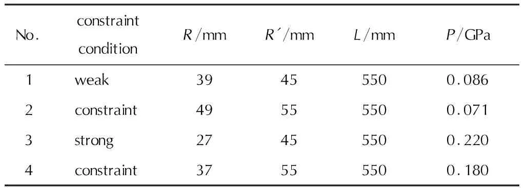
Table 1 Main parameters of DDT tube
The pressure resistance value of the No.3 DDT tube was 0.22GPa, which ensured that the DDT tube will not be damaged during the convection combustion. The longer the DDT tube is and the larger the diameter is, the easier the combustion to detonation is. And powdery emulsion explosive is low-sensitivity. To ensure that steady detonation can occur during the experiment, the length and diameter of the DDT tube designed were larger than the specifications used in relevant literature[11-12].
1.1.2 Explosive bed
According to the previous research results of DDT sensitivity, powdery emulsion explosives without aluminum powder or with low content of aluminum powder (less than 4%) were difficult to exhibit self-sustaining combustion. The sensitivity of combustion to detonation was also extremely low. Three powdery emulsion explosive samples with average particle sizes of 92, 130 and 150μm were regarded as the experimental objects, which contained 8% aluminum powder separately (particle size of 68μm), and the explosive bed was loaded at different densities in order to ensure the occurring of DDT phenomenon in the experiment[13].
Section pressing was adopted in the bed preparation to ensure the uniformity of the charging in the bed. The height of each pressing should not exceed the diameter of the DDT tube. The actual length of the bed was 455mm.
1.1.3 Ignition device
The ignition system is an important factor that affects the DDT process. Thus, we should choose a reasonable ignition device for different subjects. For easily combustible energetic materials[14-17], such as propellants, ignition is generally carried out by using an ignition cartridge.
Powdery emulsion explosive does not burn easily even if it burns with an external heat source, so it cannot sustain the burn once it is heated outside. If an ignition cartridge is used, then the maintenance of the combustion of the explosive bed is difficult to ensure. In this work, the resistance wire was used to ignite the bed. In the combustion process, the resistance wire can ensure the continuous heating of the bed. After careful processing and filtering, all resistance wires had a resistance of 250Ω and power supply voltage of 220V. The ignition device was composed of explosive lead, resistance wire, and DDT tube plug. Fig.1 shows a photograph of the ignition device used in the DDT experiment.
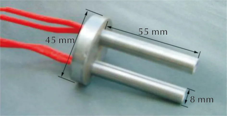
Fig.1 Ignition device
1.2 Experimental methods
The combustion rate of the powdery emulsion explosive was lower than that of simple high-energy explosives. Given that the ionization probe has no advantage in detecting low-speed combustion signals, a fiber optic probe was selected to obtain the combustion signal of the explosive bed.
During the DDT test of powdery emulsion explosive, the insertion depth of the fiber optic probe in the explosive bed directly affected the experimental result of the combustion rate signal. When the placement angle of the DDT tube was changed, the experimental results varied considerably.
Comparison and analysis indicated that this phenomenon was caused by the combustion characteristics of the powdery emulsion explosive in the DDT tube. Experiments were designed according to the probe position and DDT tube placement inclination for testing and analyzing the combustion signal in the DDT tube to explore the DDT mechanism of the powdery emulsion explosive.
1.2.1 Probe arrangement
(1) Probe layout
The 12 probe holes were arranged along the DDT tube and axially equidistant with the probe spacing of 40mm (Fig.2). At one end near the bottom of the bed, a borehole was selected, and an ionization probe was installed to test the system’s trigger signal. The 11 rest boreholes were inserted with fiber optic probes.

Fig.2 Probe arrangement diagram(1-11 are fiber optic probes, 12 is the ionization probe as the trigger signal, and 13 is the piezoresistive sensor)
The DDT experimental device after the probe was installed, as shown in Fig.3.
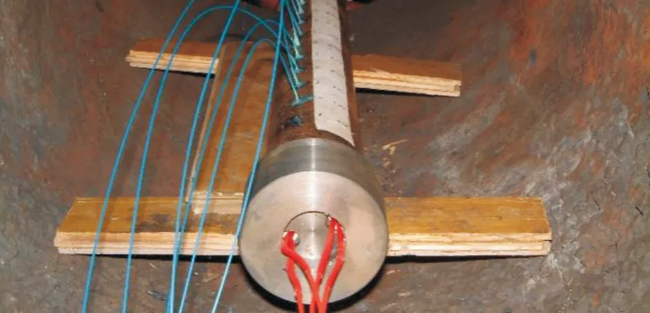
Fig.3 DDT experimental device
(2) Probe insertion position
During the DDT experiment of the powdery emulsion explosive, the insertion position change of the fiber optic probe led to the difference in the test results. An experiment was conducted to explore the law of this change by putting the DDT tube at the inner wall or central axis.
Fig.4 shows the insertion position diagram of the fiber optic probe. In the experiment, the arrangement of the probe along the DDT tube axial direction was completely consistent with that in Fig.3, except that the insertion depth of the fiber optic probe in the explosive bed was different. Fig.4(a) shows that the fiber optic probe was inserted near the inner wall of the DDT tube, exceeding approximately 3mm out of the inner wall. Fig.4(b) shows that the fiber optic probe was inserted near the central axis of the DDT tube at approximately 18mm above the inner wall.
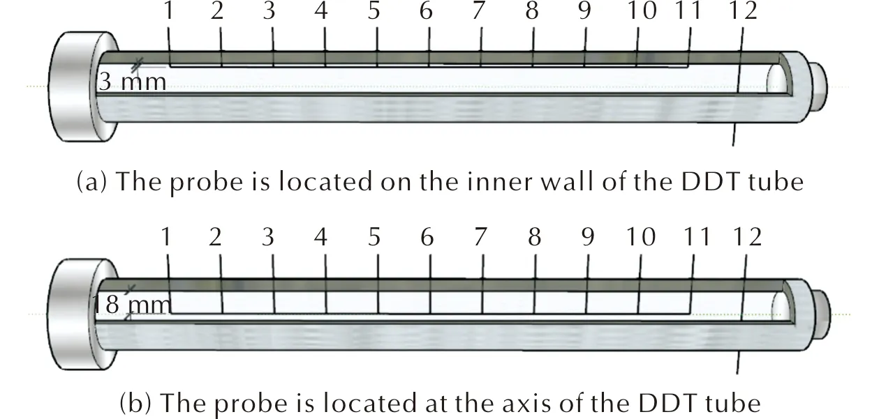
Fig.4 Diagram of fiber optic probe insertion position
1.2.2 DDT tube placement mode
Given that the powdery emulsion explosive is difficult to burn, the placement angle of the DDT tube will directly affect the combustion and flame propagation of the explosive bed. Three placement methods, namely, horizontal, vertical, and inclined, were compared (Fig.5) to conduct the DDT experiment of the explosive bed.
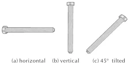
Fig.5 DDT tube placement diagram
1.3 Test system
The process of explosive combustion and detonation produces bright light due to the chemical reaction of explosives. The experiment adopted the optical fiber velocity measurement system to acquisite the optical signals to determine the combustion wave and detonation wave velocity, understanding the combustion characteristics of the explosives.
The optical fiber velocity measurement system used in this experiment was composed of a quartz fiber probe, photoelectric triode, optical fiber speed measuring instrument, and recording device. The principle of the optical fiber velocity measurement system is shown in Fig.6. The optical signal on the reaction array was collected by the fiber optic probe, and the optical signal was converted into an electrical signal through the electro-optic triode. The received electrical signal was processed into a sequential pulse signal by the optical fiber velocity measurement instrument, transmitting to the recording device.

Fig.6 Operating principle of optical fiber speed measuring system
The recording device used in the experiment was the domestic JOVIAN ammunition-integrated power testing system, which has 12 recording channels.
The fiber probe used in the experiment was formulated from pure quartz fiber, with a diameter of 400μm and an outer sheath diameter of not greater than 1.4mm.
2 Results and discussion
2.1 Test results of fiber optic probe at DDT tube inner wall
The powdery emulsion explosive with an average particle size of 130μm was ignited with different densities, and the fiber optic probe was inserted into the inner wall of DDT tube, as shown in Fig.4(a). The combustion to detonation experiments was carried out on the beds with different loading densities[18-23].
According to the original test results, the relative arrival time (relative to trigger signal) of the chemical reaction array at different positions can be obtained. Thus, the average propagation velocity of the chemical reaction array surface between adjacent probes can be calculated (Table 2).
As shown in Table 2, the average propagation velocity of the chemical reaction front between adjacent probes was extremely close, reaching above 3774m/s, and the average velocity at different positions did not change significantly. The fiber optic probe only measured the velocity of the detonation stage of the explosive bed.
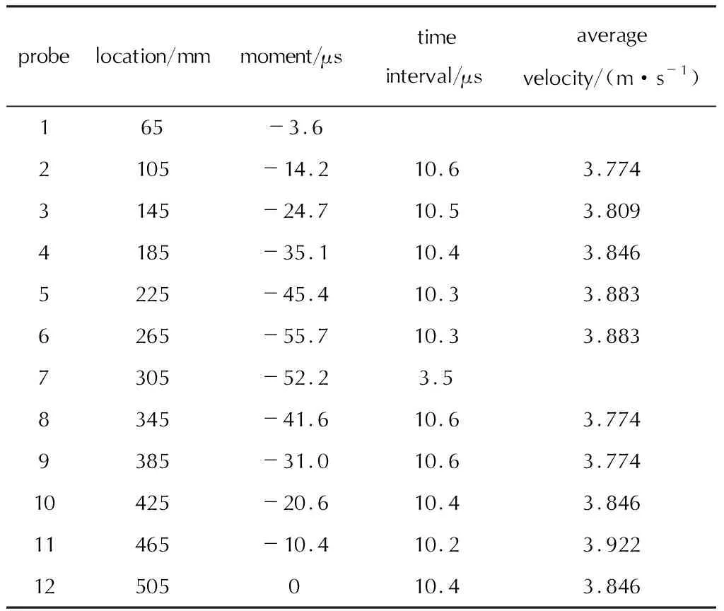
Table 2 Results of fiber optic probe on the inner wall of the DDT tube (explosive bed density was 0.78g/cm3)
Using the data in Table 2, the curve of the chemical reaction matrix over time can be drawn (Fig.7). The chemical reaction front started between probe no.6 and probe No.7 and propagated to both ends of the explosive bed. Both branches of the curve were close to straight lines, indicating that the chemical reaction front propagates to both ends of the explosive bed at a steady speed. The absolute value of the slope of each branch was the average detonation rate of the explosive bed. The intersection of the two extension lines was only the starting point of detonation, which is also the critical point of combustion to detonation.
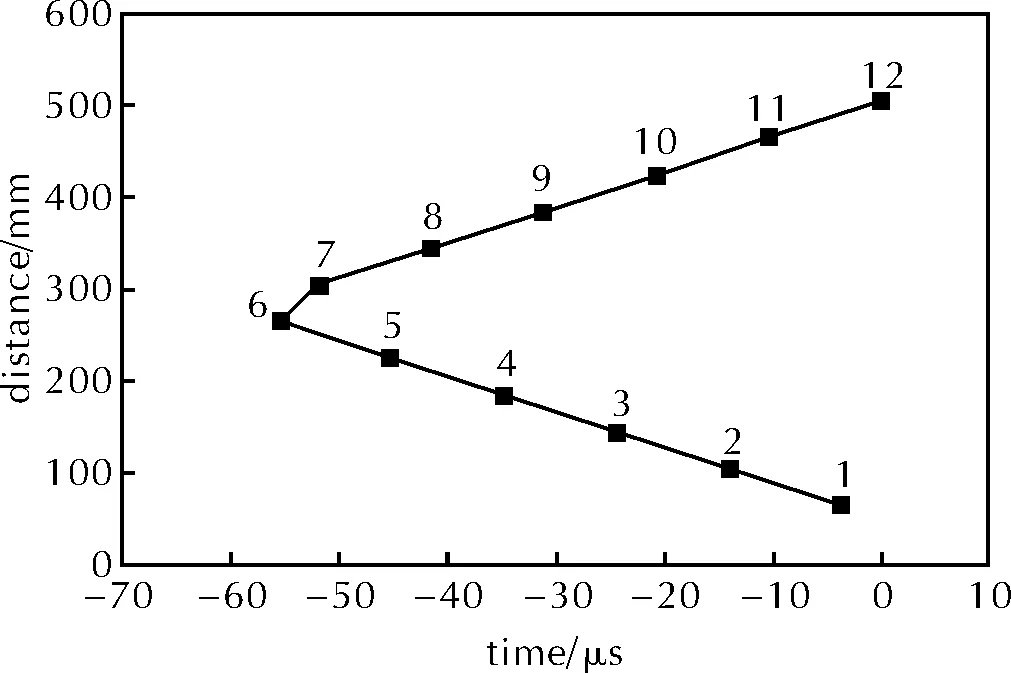
Fig.7 Relationship between chemical reaction front and time
The combustion and detonation experiments when the fiber probe is at the inner wall of the DDT tube were carried out for the loading density of 0.84 and 0.89g/cm3, respectively. The results are consistent with the previous test. The probe only measured the detonation velocity of the explosive bed. The chemical reaction front also started from the critical detonation point and propagated to both ends of the explosive bed, thereby indicating the good repeatability of the results.
2.2 Test results of fiber optic probe at the central axis of DDT tube
Based on the change in the experimental scheme (Fig.4b), the fiber optic probe was inserted into the position of the central axis of the explosive bed, and the combustion to detonation experiments were carried out on powdery emulsion explosive samples with different loading densities and average particle size of 130μm. The probe at the central axis of the DDT tube measured not only the velocity of the detonation stage but also the growth process of the combustion wave front from low speed to high speed in the entire DDT process.
Table 3 presents the fiber optic probe test results of the emulsion powder samples with the loading density of 0.78g/cm3and the particle size of 130μm.

Table 3 Results of fiber optic probe at central axis of DDT tube (drug bed density was 0.78g/cm3)
According to the data in Table 3, the relationship curve of the combustion wave front position and time in the process of DDT in the drug bed can be drawn in Fig.8.
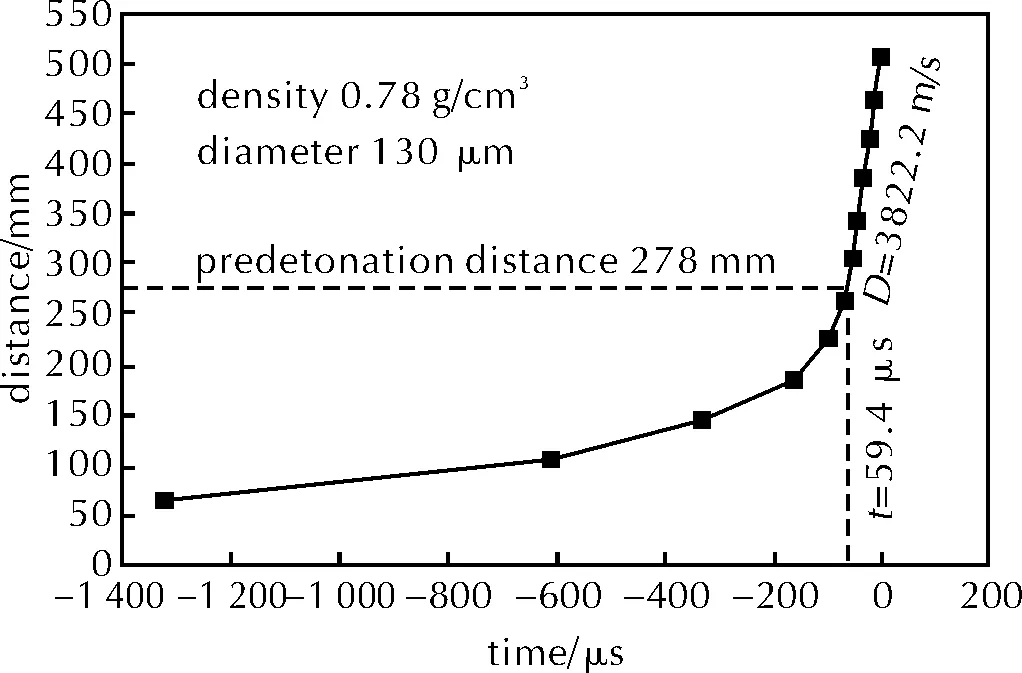
Fig.8 Relationship between combustion wave front position and time
Fig.8 shows the development trajectory of the combustion wave front in the DDT tube. In the early stage of the experiment, the combustion of the explosive bed was gradually intensified. The relationship between the position of the wave front and time was close to the exponential distribution. It was the convective combustion stage, and the combustion speed of the explosive bed increased from 56 m/s to more than 2670m/s. In the later stage of the experiment, the combustion speed of the bed increased sharply. After exceeding 3769m/s, the relationship between the position of the wave front and time was approximately linear. This stage was the steady-state detonation stage, and the corresponding average detonation speed was 3822.2m/s.
The first six points shown in Fig.8 were fitted exponentially, and the last six points were fitted linearly. The intersection of the two fitting curves was the critical detonation point. The results showed that the critical detonation point of this experiment was 278mm between the 6th and 7th probes, which was almost consistent with the result in Table 2. Hence, the positions of the critical detonation point obtained by different experiments are almost the same as those obtained by the same density and particle size.
2.3 Influence of DDT tube placement
The powdery emulsion explosive was easy to burn, and the placement angle of the DDT tube had a remarkable influence on the behavior of combustion to detonation. DDT tubes were placed in three ways in this experiment to facilitate the comparison of the combustion characteristics of the powdery emulsion explosive (Fig.5). As shown in Section 1.1 and 1.2 of the experiments, the DDT tubes were placed horizontally.
When the DDT tube was placed horizontally, the three kinds of the powdery emulsion explosives with particle sizes of 92, 130 and 150μm were tested according to different loading densities. The loading density of the explosive bed was in the range of 0.67-0.89g/cm3. No combustion to detonation was observed in the experiments with the density of less than 0.67g/cm3for the explosive bed or greater than 0.89g/cm3. Therefore, when the DDT tube was placed horizontally, as long as the loading density of the explosive bed was appropriate, the explosive bed continue to burn smoothly until detonation occurred. If the density of the bed was extremely small or large, the phenomenon of combustion to detonation was not easy to occur.
When the DDT tube was placed vertically and tilted (45°, Figs.5(b) and (c)), combustion to detonation experiments were conducted on the explosive beds with loading densities of 0.82, 0.84, and 0.89g/cm3, respectively. The explosive beds were extinguished shortly after being ignited, and no detonation occurred. Table 4 presents the DDT experimental results of the vertical and inclined explosive bed.
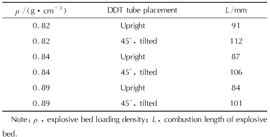
Table 4 Results of explosive beds with different loading densities when DDT tubes were placed vertically and tilted
When placed vertically, the bed burned to 84-91mm and went out. The surface of the unburned bed was concave and sagged to the axis of the DDT tube, and 8-13mm-thick unburned explosives were present on the inner wall of the tube. The unburned charge was covered with a thin layer of solid. When placed at an angle, the explosive bed burned until it was extinguished at 101-112mm. The surface of the unburned bed was approximately concave, and the deepest burned area was above the axis of the DDT tube. The inner wall of the tube was covered by 6-13mm-thick unburned explosive. The unburned charge was covered with a thin layer of solid.
As shown in the table, the combustion length and phenomena of the explosive bed in the tube were also different due to the different placement methods of the tubes. After the combustion of the explosive bed was terminated, a thin layer of solid was covered over the unburned explosive, which was the product of the powdery emulsion explosive after melting and solidifying.
2.4 Combustion characteristics analysis
The different positions of the fiber optic probe in the DDT tube resulted in varying test results, which was related to the combustion characteristics of powdery emulsion explosive. Fig.9 shows a photograph of a DDT tube whose combustion had not been converted to detonation. A layer of explosives with different thicknesses remained on the inner wall of the burned tube, indicating that the explosives in the cross-section of the explosive bed did not burn at the same time when the combustion wave passed through. The deepest burned area was above the axis of the DDT tube. After the combustion was extinguished, the melted emulsion powder solidified and coated the unburned explosive.
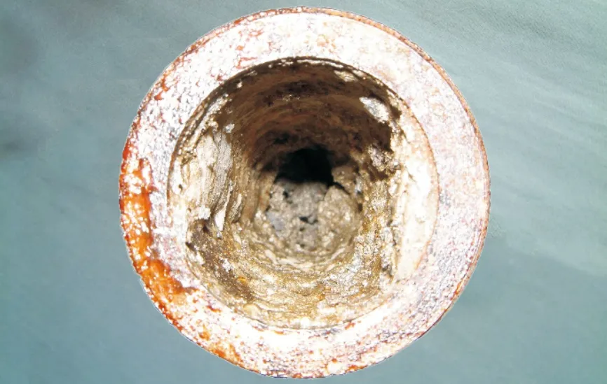
Fig.9 Photograph of DDT tube without detonation
After measurement, the thickness of the unburned explosive on the inner wall of the tube was within 6-12mm (measured at the position of 50mm from the ignition end face). The closer to the unburned zone is, the thicker the unburned explosive layer on the inner wall of the tube will be. The emulsified powder explosive started to burn in the middle of the bed and spread along the axial and radial directions. The combustion speed of the explosive in the axial direction was higher than that in the radial direction. This phenomenon could be due to two reasons. On the one hand, the radial distance of the explosive bed was less than the axial distance, and the expansion of the explosive combustion gas products quickly compacted the unburned explosive near the inner wall of the tube, which was not conducive to the convective combustion of the explosive. On the other hand, the external temperature was extremely low, and the DDT tube was not adiabatic compared to the combustion of explosives because the steel tube is a good conductor of heat. Hence, the temperature of the explosives near the wall of the tube is low, which is not conducive to combustion.
The failure of the fiber optic probe inserted into the inner wall of the DDT tube to detect the combustion signal can be easily explained by the combustion characteristics of the explosive in the explosive bed. Given that the combustion speed in the axial direction of the explosive bed is much higher than that in the radial direction, which may be caused by heat absorption of the wall or the reflection of the pressure wave at the wall. Due to the limited equipment conditions, this problem needs to be further studied. And the combustion wave accelerated forward along the axis of the explosive bed, while a certain thickness of the explosives was still present on the inner wall of the DDT tube. Thus, the fiber optic probe inserted in the inner wall of the DDT tube cannot naturally receive the combustion signal. The light probe on the inner wall of the tube did not receive the light signal until the axial combustion of the bed changed to detonation and spread to the unburned explosives at both ends of the bed, and the measured velocity was the detonation velocity of the bed.
The above experiments showed that the powdery emulsion explosive first melted before burning. Under the action of gravity, the liquid explosive had to flow downwards. When the DDT tube was placed horizontally, the explosive at the combustion wave melted and flowed continuously toward the ignition head. In this way, the explosive can receive continuous heating from the ignition head and accelerate the combustion to the point of detonation. When the DDT tube was placed vertically or tilting upward, the melted explosive was concentrated near the combustion wave. The presence of liquid explosive resulted in the difficulty of the permeation of combustion gas to the unburned explosive bed, which is not conducive to the convective combustion of the explosive. After the explosive near the ignition head burned out, the heat generated by the ignition head cannot directly act on the unburned explosives. Without sufficient energy, powdery emulsion explosive cannot self-sustain combustion[8]. Therefore, the combustion of the explosive bed is quickly extinguished.
3 Conclusions
(1) As an insensitive industrial explosive, the powdery emulsion explosive cannot burn by itself without sufficient external energy support after being ignited. Under strong energy, the explosive bed with suitable density will accelerate combustion until detonation occurred.
(2) In the process of combustion to detonation of powdery emulsion explosive, the combustion wave array propagated in the axial and radial directions of the DDT tube, and the axial propagation speed is higher than the radial velocity.
(3) In the process of combustion to detonation of powdery emulsion explosive, the combustion signal of the explosive bed cannot be obtained at the inner wall of DDT tube. Thus, the detonation signal can only be obtained. The accurate combustion speed and detonation signal can only be measured by inserting the fiber optic probe into the position of the axis of the explosive bed.
(4) The powdery emulsion explosive first melted before combustion. When the DDT tube was placed vertically or at an angle, the liquefied explosive bed was far away from the ignition head under the action of gravity. Thus, the continuous heating of the ignition head cannot be obtained, the combustion cannot be maintained, and the detonation of the explosive bed will not occur. Only the proper placement of DDT tube can ensure the continuous combustion of the explosive bed during the experiment.

