The Influence of the Casing Grooves on the Performance of An Axial Compressor
Naseem Ahmad Ghulam Ishaque Arif Aziz Zubair Ali Shah Mushayyed Muhammad Ali Khan Qun Zheng
(1.Department of Mechanical Engineering,Institute of Space Technology,Islamabad,Pakistan 2.College of Power and Energy Engineering,Harbin Engineering University,Harbin,China)
Abstract:The stable range of the gas engine compressors is reduced due to per stage maximum loading.The performance of the engine is closely associated with stable operating conditions.The instabilities of the flow occur if some rapid changes happen in the operating conditions and it leads to a rotating stall.To avoid such conditions,the proper stall margin should be maintained for the performance of the axial flow compressor.The stall margin can be enhanced by the blade tip and casing treatment.The casing treatment is commonly used to increase the stall margin of the axial compressor.The present numerical study investigated the performance of casing grooves on NASArotor 37 by discretizing 3D RANS equations with the help of the finite volume method.One passage steady simulation is carried out for validation.The simulation results agree well with the experimental data for total pressure ratio and efficiency.The stall is predicted according to convergence criteria.The rectangular grooves model has been proposed and tested numerically.The performance of rectangular grooves and smooth wall casing is evaluated.The stall margin of the rectangular grooves model is increased by 6.37%as compared to the smooth casing.TLV is minimized with the help of the installation of grooves that reduced the vortex stagnation zone and supports to improve the stall.The stall margin of the axial compressor with casing grooves is remarkably enhanced but efficiency is slightly reduced.
Keywords:Numerical Simulation;Casing Treatment;Stall Margin;Axial Compressor;Adiabatic Efficiency
Nomenclature
RANS Reynolds averaged Naiver Stokes
CGCT circumferential grooves casing treatment
SST shear stress transport
LE leading edge
TE trailing edge
SM stall margin
Pt total pressure ratio
TLV tip leakage vortex
PS pressure surface
SS suction surface
Tt total temperature
γratio of specific heat
y+non-dimensional wall distance
TCF tip clearance flow
0 Introduction
The axial compressor design is significant for gas turbine such as marine engine,aerospace engine,and jet engine.Axial compressors have high performance,high reliability and flexible operation.Axial compressor is a major part of the gas turbine engine because of these reasons.Though,unavoidable surge or rotating stall always brings severe vibration and performance deterioration when the compressor is approaching stability limitation.To grasp the utmost advantages,the flow range of the compressor should be maximized.
Numerous researchers have used several experimental and CFD techniques to investigate the stall and surge mechanism to improve the axial compressor performance.Schlechtriem and L?tzerich [1]and Yamada et al]2]investigated that stall is triggered at the leading-edge due to the breakdown of the blade tip leakage vortex (TLV).Lang et al]3]used multi passage unsteady simulations to investigate the install behavior of axial compressor.They showed that breakdown of TLV is arisen due to the interaction between detached shock wave and tip leakage at the stall.The TLV goes downstream and formed a new vortex.The blockage occurred in the blade tip region,because of these vortices.
Tip leakage vortex is the basic factor of the axial compressor instability adjacent to the blade casing region.The passive casing treatment technique controlled TLV to improve the operational range of the compressor,but adiabatic efficiency is slightly decreased with the casing treatment.Numerous approaches have been suggested to increase the stall margin of the compressor.Bailey [4]experimentally tested the solid casing wall with different casing grooves.Aluminum removable inserts grooved configurations is used for modifications.The depth,location and number of grooves were changed for circumferential grooves.The results showed that using the casing grooves is beneficial to improve the stall margin and compressor stability.
The analysis of casing grooves depth and width is conducted by Huang et al]5]to increase the performance and stall margin.They reported that the stall mechanism is significantly affected by tip clearance.Experimental work has been done by Houghton and Day [6]using single casing groove to modify the axial location for efficiency,stall margin and stability.They reported that the interaction of grooves in aft and forward location is changed.While in another research,a single groove with various depths and position have been numerically tested by Choi [7]to assess the axial compressor performance on geometric parameters.He revealed that the fixing of a groove close to blade LE is very efficient and increased the stall margin up to 3%,and reduced a small efficiency.
A single groove with changed axial position using NASA rotor 37 is investigated by Sakuma et al]8].According to their conclusion,the tip loading and TLF momentum are reduced by casing grooves.The influence of casing grooves with three different methods on the low-speed axial compressor is experimentally examined by Rolfes et al]9].He revealed that the compressor operational range is improved via casing grooves.The impact of ACG on low-speed axial compressor is reported by Hah[10]to find the compressor stall margin and efficiency.He showed that fixing the ACG improved the stall margin without any penalty of adiabatic efficiency.Multiple grooves installed in different groove axial location is numerically researched by Song et al[11].
Ross et al]12]used several tip clearances with the grooves to increase the stall margin and performance.They concluded that the stall margin is enhanced with the grooves and further explains that SME linearly increases with the momentum flux.A numerical study is conducted on a single groove by Naseem et al]13]and revealed that stall margin and stability of the axial compressor is enhanced with casing grooves.
The main objective the present research is to focuses and design three circumferential grooves to increase the compressor stability and performance using NASA rotor 37 to analyze RANS 3D equations numerically.The stall margin,adiabatic efficiency and total pressure ratio of the CGCT model are evaluated with smooth wall casing and experimental data to determine the impact of circumferential grooves on stall margin and adiabatic efficiency.
1 Detail Design Condition of NASA Rotor 37
NASA rotor 37 a high-pressure ratio axial compressor is selected for the present investigation.The ample information of the compressor design conditions is listed in Tab.1 that is taken from AGARD report [14]The compressor rotor consists of 36 blades and the rotational speed is 17188.7 rpm.The total pressure ratio of the compressor rotor is 2.106 and 88.9 % is polytrophic efficiency at the design mass flow rate of 20.19 kg/s.Mass flow rate at choked limit is 20.93 kg/s.The tip height is 0.356 mm(47%span).
NASA rotor 37 meridional plane is represented in fig.1.Measured the flow parameters,total pressure and total temperature at inlet station 1 that are linked to mass flowrate at outlet station 2 is shown in Fig.1.The upstream distance between station 1and the blade leading edge is-41.9 mm whereas station 2 is positioned at 106.7 mm downstream from blade TE adjacent to hub consequently.
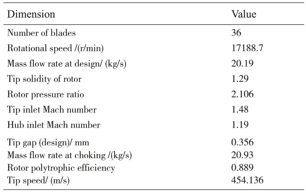
Tab.1 Design specification of Rotor 37[14]

Fig.1 Description of Rotor 37 on meridional plane
2 Design and Description of CGCT
Three rectangular CGCT for NASA rotor 37 are designed in the present study to increase the stability and performance of the compressor and it is demonstrated in Fig.2.The performance of the casing grooves model is evaluated with the normal casing.Three grooves are fixed on the compressor rotor shroud and the grooves are located from 18%58 % of the axial chord of the blade.The grooves height is five millimeters and the width of each groove comprises of 10% axial chord of the blade.There is a five percent gap between the two grooves.Basically,the CGCT technique is used to increase the performance and operating range of an axial compressor.

Fig.2 Casing grooves profile shape
3 Numerical Technique
Ansys 17 [15]is used in this study by applying a 3D steady governing flow analysis.3D RANS equations are discretized using the method of finite volume.Numeca Autogrid 5[16]and CFX are used for making mesh and simulations.Casing grooves and fluid domains are generated in design modeler and ICEM CFD is used for mesh generation correspondingly.The computational domain of single passage is used in this study by adopting periodic flow condition in the rotation of circumferential direction between two blades.Structure mesh are generated in an axial compressor flow passage and it is illustrated in Fig.3.HOH topology is adopted for structure mesh.The compressor rotor blade LE and TE are generated with O form mesh and H form grids are adopted for the main flow section.H form grids are also selected for the grooves.The number of inlet grids is 17×29×40 and for the outlet block,the number of grids is 17×33×40.The number of grids for every groove block is 20×30×60.The total number of nodes used in this study are 4.45×10⁵.The three cases used for grid dependency is shown in figure 3.The graph is made between streamwise location and pressure at mid-span.For the three cases,the number of grids is 222000,445000 and 780000.It could be notice in fig.4 that changed the number of grids from 445000 to 780000,the pattern is not changed.So,the case of 445000 is selected for the present study.This study selects shear stress transport model for numerical simulation.Bardina et al]17]and Hamza et al]18]showed that the SST turbulence model is much proper for the separation flow of adverse pressure gradient investigation.The minimum y+value is adjusted below three to seizure the wall share stress precisely.Working fluid air gas is chosen for this study.At inlet 1 atm of total pressure and 288.15 K of total temperature is selected.The blade passage interface is set periodic.At the outlet,the radial equilibrium condition is imposed.Close to stall limit,50 Pa backpressure is increased.The last stable point is considered near the stall point.GGI technique is used to connect the blade passage and grooves.The convergence criteria suggested by Huang et al]5]is used in this study.
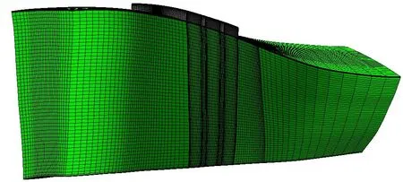
Fig.3 One passage mesh computation of rotor 37
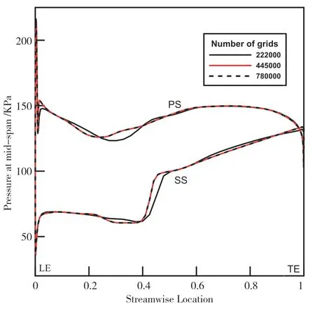
Fig.4 Grid sensitivity test
4 Result and Discussion
The validations of total pressure ratio and adiabatic efficiency is taken from the previous research,Naseem et al]19].The CFD simulations show fair agreement with the tested data for adiabatic efficiency and total pressure ratio and it is shown in Fig.5.In an axial compressor the method of casing grooves is normally used for the stability and performance enhancement.
To enumerate the axial compressor performance and stability,the SM and adiabatic efficiency parameters are chosen in the current study and these parameters are described as follows.
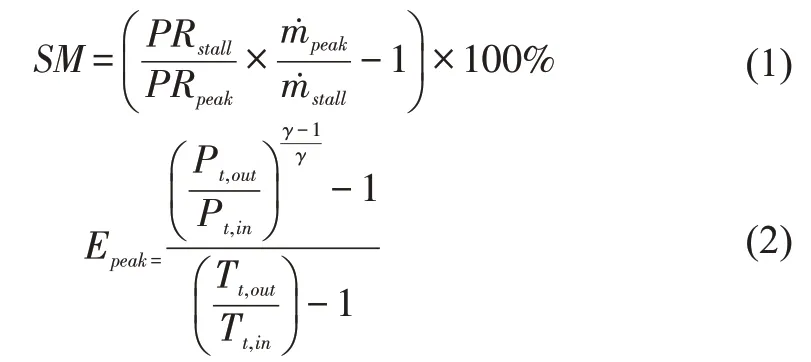
Where PR andm˙ are total pressure ratio and mass flow rate.The peak and stall subscripts pressure ratio and mass flowrate at peak and close to stall point respectively.Pt,Tt,andγrepresent total pressure,total temperature and specific heat ratio correspondingly.
Tip flow leakage and TLV guides to stagnation zone and this moves downstream to the passage shock owing to low mass flowrate,and vortex breakdown is arisen.It develops to extreme blockage in the main flow zone resulting unsteadiness in the axial compressor.The phenomena of TLV breakdown is common in NASA Rotor 37.Stall margin,adiabatic efficiency and total pressure ratio are performance parameters of the compressor.The near stall condition for normal casing and casing grooves model are 0.911 and 0.907 respectively.The total pressure ratio of the normal casing and casing groove model close to stall limit is 2.14 and 2.16 respectively.The total pressure is slightly higher for the casing grooves model,than the normal casing.This difference is shown by several scholars Sakuma et al]8]and Huang et al[5].
Adiabatic efficiencies of normal casing and casing grooves model are 88.31 percent and 88.08 percent and the efficiency are higher than efficiencies presented by Choi [7].The efficiency of the casing grooves model is slightly reduced than the smooth wall casing as there are three grooves installed between 18% to 58 % and there is no groove fixed at leading and trailing edge of the blade and the location of the grooves among the mentioned location is very efficient.The CGCT play important role by reducing mass flow close to stall limit as compared to normal casing and with this reason the stall margin is enhanced.Total pressure ratio and higher efficiency can be gained in the range between peak efficiency and close the points of the stall by fixing the CGCT but there is a minor decrease in the efficiency.So,the blade pressure surface separation that is shaped due to loss of pressure is reduced by momentum flux of the CGCT.This minimize the blockage in the grooves location which rises on the pressure surface of blade as depicted in Fig.6(a)and the separation is stifled with the CGCT installation Fig.6(b)and finally the Mach number is recovered at the blade suction surface around the blade.The Mach number is recovered in the grooves location in Fig.6 (b) which can be observed easily.With the help of CGCT momentum flux is formed on the pressure surface to blade suction surface and the same is reported by Choi [7].Due to suppressed separation at suction surface of the blade,it benefits to increase the axial compressor performance and operating stability.
The adiabatic efficiency and stall margin comparison of smooth wall and CGCT model are represented in Fig.7 and 8 respectively.The adiabatic efficiency of the CGCT model is decreased slightly with the fixing of the casing grooves.The smooth casing higher efficiency is 88.31% in Fig.7,whereas the adiabatic efficiency of CGCT model is minimized by 0.23 %.So,a small difference in the efficiency of the CGCT model and smooth wall casing.

Fig.5 Validations of rotor 37 for total pressure ratio and adiabatic efficiency[19]

Fig.6 Mach number contours at 98 percent span(close stall limit)for(a)smooth wall and(b)CGCT model
The grooves are fixed at the position of 18%to 58%of the blade chord and the grooves are much influential in the above-mentioned position,that is why there is a minor variance in the efficiencies of the CGCT model and smooth wall casing.
The model has a better influence on the axial compressor stall margin as shown in Fig.8.The stall margin gained in this research work is greater than the stall margins reported by Huang et al]5].In Fig.8 the stall margin of the CGCT model is 19.52 percent while the stall margin of the smooth wall casing is 13.15 and 6.37 percent stall margin is enhanced.It is thought that the first two grooves which are fixed at 18% and 38% of the blade chord give more input to augment the stall margin whereas the third groove gives a small role to maximize the stall margin.According to the author,the CGCT model has a decent effect on the extension and improvement in the operating condition of the axial transonic compressor.
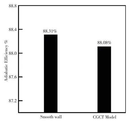
Fig.7 Comparison of adiabatic efficiency of a smooth wall and CGCT model
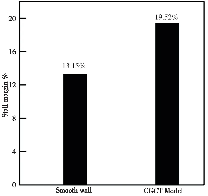
Fig.8 Comparison of the stall margin of a smooth wall and CGCT model
Entropy contours of the smooth casing and CGCT model at 98 % span (close stall limit) are illustrated in Fig.9.It can be seen in Fig.9 that the CGCT model has a higher entropy value at the tip of the blade.The CGCT model displays small values of entropy in downstream region,with the fixing of grooves except the smooth casing and this agree pretty well with the research work reported by Choi et al]7].This decreasing of entropy creation illustrates the improvement of the TLV structure.The value of entropy in the downstream region is further lesser because there is no groove to fixed blockage of the TLV.With fixing of casing grooves,the efficiency is recovered in the low flow mass zone owing to the smaller value of the entropy instigation.

Fig.9 Contours of entropy at 98%close stall condition
The static pressure contours are illustrated in Fig.10 close to stall limit at 98 percent span for smooth wall casing and CGCT model.Fig.10(a)demonstrates that there is a notable contiguous pressure gradient at the PS adjacent to the LE of the blade.This feature is more severe in the TE of the blade and the this is also the central region of the TLV.The contours of static pressure close to the blade LE at Fig.10(b)are less increased in the CGCT model due to the fixing of circumferential grooves and the grooves suppress the TLV which helps to increase the stability of the compressor.The casing grooves are installed between eighteen to fifty-eight percent so no high pressure is observed there.Slowly the pressure gradient is melted and the reduced the local pressure in the groove's position.The low static pressure transfers to the blade SS close to the blade tip.TLV and main flow combined due to leakage flow,and create more blockage close to the blade tip at trailing edge.
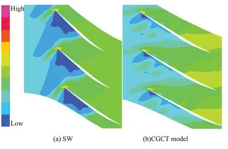
Fig.10 Contours of static pressure for(a)smooth wall and(b)model 1 at 98%span
5 Conclusions
The effect of circumferential grooves on the stall margin and adiabatic efficiency using 3D RANS is numerically studied in the present research study.Findings of the current research work are following.
1)The vortex stagnation zone is generated due to the interaction between a shock wave and TLV caused unsteadiness in the axial compressor.There is a significant impact of blade pressure surface separation on the inception of the stall in an axial compressor.
2)With the help of casing grooves,the vortex stagnation zone is reduced.The tip gap flow is reduced by fixing the circumferential grooves,which reduced the vortex stagnation zone and enhance the performance of the compressor.
3)It is observed that the first two grooves produced significant enhancement to the stall margin,whereas,the last groove has a little effect on the stall margin.
4)The efficiency of 88.08 percent and stall margin of 19.52 percent are achieved by fixing the grooves on the axial compressor.
5)The maximum adiabatic efficiency is slightly decreased with the installation of circumferential grooves.Due to corner separation entropy is produced and combine with reverse TLF causing a decrease in the efficiency of axial compressor.
- 風(fēng)機(jī)技術(shù)的其它文章
- 某二氧化碳離心壓縮機(jī)轉(zhuǎn)子次同步振動分析
- 透平機(jī)械數(shù)字孿生與智慧運(yùn)維大會暨第一屆中國國際透平機(jī)械產(chǎn)業(yè)聯(lián)盟前沿科技大會在沈陽成功召開
- Effect of Solid Heat Conduction on Accuracy and Efficiency in Steady-state Liquid-crystal Measurement of Flat Gas Film Heat Transfer Coefficient*
- 凹坑對風(fēng)力機(jī)翼型氣動性能的影響*
- 前導(dǎo)葉結(jié)構(gòu)參數(shù)對大型軸流風(fēng)機(jī)氣動噪聲的影響研究*
- 多聯(lián)空調(diào)室外機(jī)噪聲的實驗測試研究*

