Quantitative analysis of the morphing wing mechanism of raptors:IMMU-based motion capture system and its application on gestures of a Falco peregrinus
Di Tang(唐迪), Liwen Zhu(朱力文), Wenxi Shi(施文熙), Dawei Liu(劉大偉),Yin Yang(楊茵), Guorong Yao(姚國榮), Senxiang Yan(嚴(yán)森祥), Zhongyong Fan(范忠勇),Yiwei Lu(陸祎瑋), and Siyu Wang(王思宇)
1College of Mechanical Engineering,Zhejiang University of Technology,Hangzhou 310014,China
2High Speed Aerodynamic Institute,China Aerodynamics Research and Development Center,Mianyang 621000,China
3Department of Radiation Oncology,The First Affiliated Hospital,Zhejiang University,Hangzhou 310009,China
4Zhejiang Museum of Natural History,Hangzhou 310014,China
Keywords: Falco peregrinus,IMMU-based,motion capture system,flapping gesture
1.Introduction
Analysis of wing kinematics is a key technique to study the biomechanical joint motion of nature birds.However,capturing the wing movement accurately is difficult because of the complex wing structure and the changeable flapping rules.At present, the existing motion capture system can not be effectively used in the motion capture of birds.
Motion capture system has been widely used in several application areas, such as medical rehabilitation, sports, film and television production and bionics research.[1]To identify the movement posture of the creature, the position, velocity,direction,and other information of the moving subject need to be accurately measured by certain attitude capture technology.At present,there are two commonly used motion capture technologies, optical-based and contact-based devices.[2]Opticsbased devices capture video streams for analysis to determine sample motion.On the other hand,contact-based devices are precisely required to interact with the space of the sample.Based on the optical method,the sample usually does not need to install additional equipment due to the influence of external equipment on the sample motion.Samples can be more flexible with activities, but it is more susceptible to environmental disturbances such as occlusion, reflectance, and other environmental factors.[2]Furthermore, the equipment and operation process requirements are more stringent.In comparison,contact-based devices are easy to implement.Examples of contact-based devices are mobile touch screens, electromyographic (EMG)-based devices, and data gloves.The EMGbased device is portable, but the EMG signal is easily influenced by acquisition placement,individual differences,physical condition, and other factors.[3]Moreover, the movement of fine biological samples, especially birds, remains elusive.Attitude acquisition equipment such as an optical fibre sensor, pressure resistance sensor, pressure sensor, magnetometer, accelerometer, and gyroscope, to perceive movement.[4]This kind of method can well reflect the spatial motion trajectory, attitude and time series information of samples by capturing the information restricted by environmental conditions,such as the position, direction, and angle of samples.However,most products adopt wired data transmission mode,and the complex line will have a certain degree of influence on the movement of the sample itself, and the precision of the product needs to be improved.Therefore, developing a highprecision and lightweight attitude acquisition device with a wireless data transmission function for birds has become the goal of our research.As long as the frequency of data acquisition is increased, the device can obtain enough data to offset the impact of a small amount of data loss in the wireless transmission process,and the impact of the device on the attitude of the sample itself can be ignored.With the deepening of bionics research, the research requirements for the movement of biological samples are also further improved.Especially in the field of bionic aircraft, imitating and learning from the excellent flight posture of birds to obtain better flight performance is the basic idea of the design of morphological bionic aircraft.Bird flight posture has many characteristics,such as flexibility,changeability,and high frequency.Employing digital particle-image velocimetry, passerines have been found to control flight posture by coordinating tail and wing movements.[5]Three-dimensional (3D) laser scanners were used to reconstruct the shape of bird wings to analyze kinematics during flight.[6]Because birds use their wings in different ways in different flight movements,their roles in adjusting the position during complicated maneuvering remain largely unknown.At present, there are three main ways to study the flight posture of birds (as shown in Fig.1), which are wind tunnel experiment observation, bird kinematics model calculation,and optical scanning.It is difficult to fully analyze the attitude of birds with the data obtained from the existing equipment.There are a few optically based devices that can capture bird pose under harsh conditions but can seriously lose data in complex environments,such as motion capture of birds moving through dense forests.Consequently, attitude acquisition equipment is developed to obtain accurate and usable bird attitude data.The above sensors measure the relative orientation of articulated segments by mounting the sensor across the joint of interest.Sensors are installed at specific locations to measure relative positions.Moreover,recalibration is necessary to mitigate estimation errors due to sensor displacements.
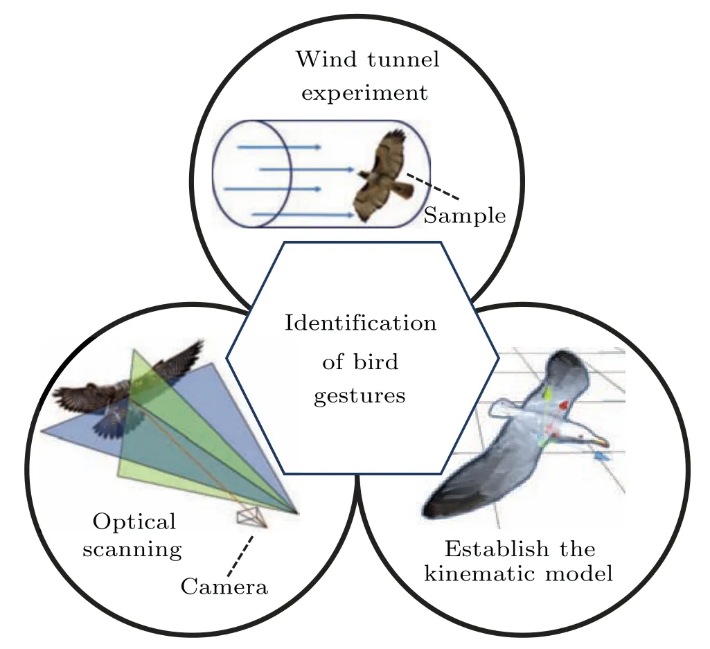
Fig.1.Methods of bird posture study.
In the recent years, micro-electro-mechanical system(MEMS) technology has made a breakthrough in development.Compared with traditional sensors, micro inertial sensors have many advantages such as high precision, low cost,and small size.Conservatively, it can be used as a sensor to measure the attitude of birds and other special situations.Meanwhile, the magnetic sensor and inertial sensor are induced for accurate azimuth estimation.The inertial magnetic measurement unit(IMMU)has proven to be an accurate method for estimating sample orientation without additional optical equipment.[7]These devices are highly accurate, simple to control and intuitive to use.Furthermore, wearable inertial sensors and magnetic sensors are becoming increasingly popular in attitude acquisition.
The application of attitude sensors in bionics is still in its infancy.Motion capture devices based on micro inertial sensors can provide more accurate attitude results than other types of devices.Motion capture systems for the human body can generally be divided into three types,which are hand-held,wrist-wearable, and glove types.The KHU-l data glove[8]consists of six three-axis accelerometers, but it can only capture several kinds of gestures.The motion-capture system developed by Bor-Shing Lin is developed based on sixteen microinertia sensors.[1]It can capture the movements of each finger and palm, but the information on the heading angle is missing.The inertial and magnetic measurement unit is used by Filippo Cavallo, but it only uses four inertial and magnetic measurement units, which is unable to obtain information about each finger joint.[9]The development of the Power glove[10]includes six nine-axis micro-inertial sensors and ten six-axis micro-inertial sensors.The above motion capture systems are difficult to be applied to bird pose capture.For birds,these capture systems are too large to ensure accurate data,and the complex electrical wiring can have a great impact on the attitude of the bird itself.Therefore,a motion capture system using low low-power 9-axis motion tracking device has been developed,which can fully capture the movement information of birds during flight.
On the other hand,the IMMU-based device should be focused on the following two main aspects: calibration and fusion algorithm.Calibration is an important means to improve the performance of IMMU.Due to the differences in external signals,materials and other environmental factors,attitude sensors will inevitably produce errors, so calibration methods should be designed to improve accuracy.Therefore, the measurements of magnetometers are the combination of the earth’s magnetic field and the extra magnetic field caused by the environmental effects.Hence, magnetometer calibration should be implemented to lessen the disturbance and improve the azimuth angle.The Kalman filter is a useful tool for sensor fusion.The extended Kalman filter is an efficient azimuth estimation method, which has been applied to many kinds of devices.Kalman filters have been shown to improve the estimation accuracy of data in wireless sensor networks with less computation.[11]Complementary filters are the high-pass signals provided by gyroscopes and the data from low-pass accelerometers and magnetometers which provide relatively accurate measurements at low frequencies fused to estimate the true orientation.[2]
Although systematic investigations of ornithopters for bionic bird flight have been undertaken for decades,[12]no aircraft can perfectly replicate the movements of birds.Part of the problem is that it is difficult to obtain precise and quantitative information about bird wing posture.[13]A broad consensus confirms that bird wing shapes are coordinated under the cooperation of muscles,skeletons,and nerves.[14]The motion capture device proposed is developed to capture bird motion data based on the IMMU-based motion capture system.The paper is organized as follows.Section 2 presents the designs of tiny motion capture devices with high accuracy.Section 3 describes the sensor calibration and attitude estimation algorithms, as well as the bird motion capture method.Section 4 reports calibration results, and bird motion capture experiments, which verify the accuracy of the proposed device.Section 5 gives the conclusions of the paper.
2.Hardware of IMMU-based motion capture system
2.1.Design of IMMU-based sensor
The development trend of the wireless measuring unit is higher precision with a small size in the current research.A control module and a transceiver module are always contained in a unit.However, the large geometry size will make it difficult to put the unit on the bird wing surface.Moreover, it is difficult to add more IMMUs with small distances to benefit from redundant measurements or gain more accurate measurements of wing motions.Here,The ICM-20948,with its 9-axis integration,on-chip digital motion processor(DMP),and runtime calibration firmware, is the world’s lowest-power 9-axis motion tracking device.The devices are all integrated in a small 3 mm×3 mm×1 mm quad flat no-lead(QFN)package.Hence,it is suitable for the light-weight IMMU with high precision and low power consumption.Both the size and weight of the measuring unit can be dramatically reduced by introducing ICM-20948.Also,all electronic components are carefully arranged on the 4-layer PCB board.As a result, the developed tinny devices can be securely attached to the bird’s wing,which makes it more accurate and easier to use.The reduction in equipment size also means that the equipment is less susceptible to external interference.The ICM-20948 sensor is welded on a solid PCB with dimensions of 20 mm×22 mm and a weight of 2.5 g,as shown in Fig.2.
Connectivity is another important issue in the design.The wired networking approaches for the connections are convenient.However, it requires many electrical lines to be connected,and the complex electrical lines of the system will inevitably affect the wing posture and data authenticity.Thus,a wireless network approach is adopted in the system.Each sensor node contains a measuring module, a control module and a transceiver module.All measured data are transmitted from child sensor nods to the hub node in sequence through the transceiver module to ensure that each group of data is in the same moment of motion.Meanwhile,The microcontroller unit (MCU) only needs to read and send data from a single IMMU, reducing the complexity of the system and increasing the data transmission rate.Here the STM32F411 microcontroller and NRF52 microcontroller are used.Since all the sensor nodes operate independently and have no spatial connection, the sample can restore the gesture to the maximum extent.
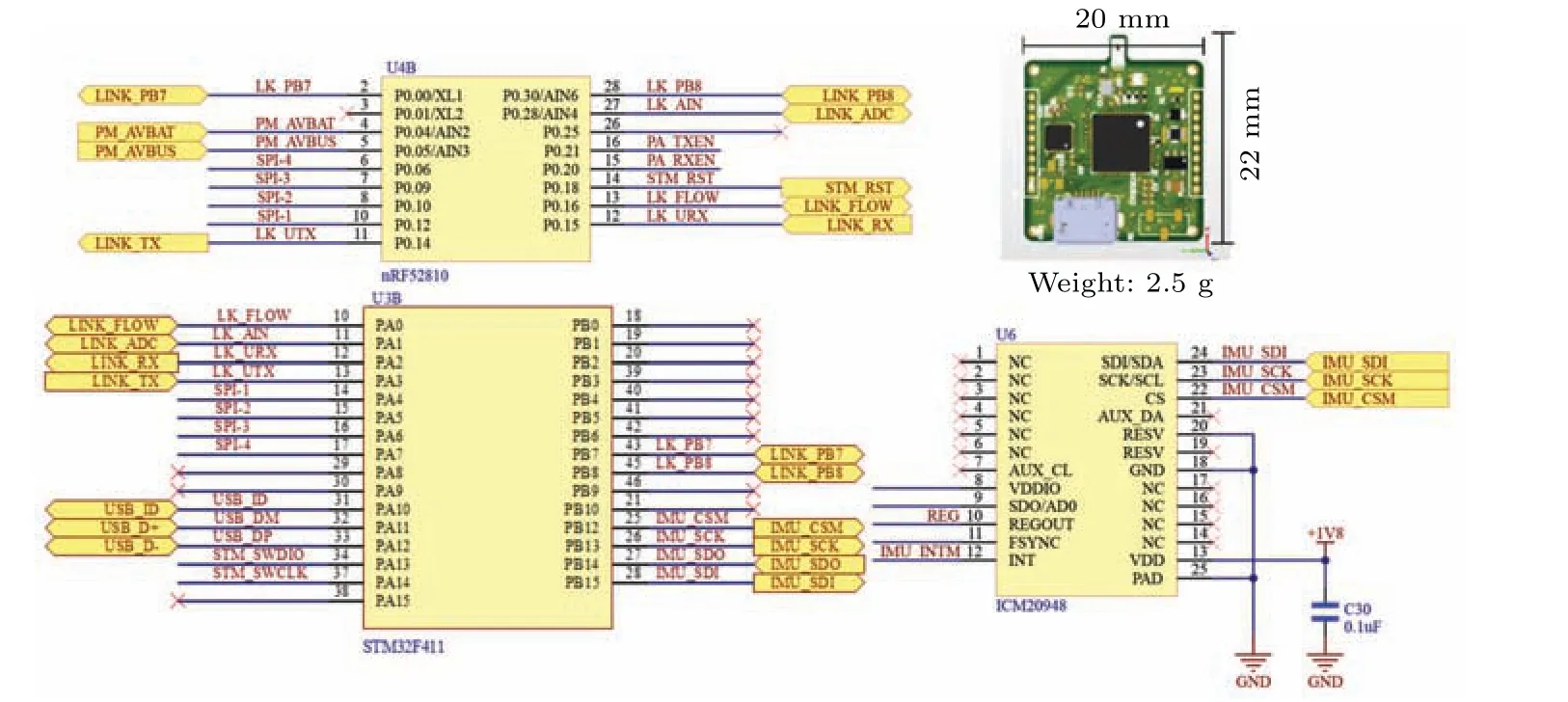
Fig.2.The connection between the chips and the overall size.
2.2.Hardware of the motion capture system
After determining the IMMU-based measuring unit, the design of the motion capture system can be determined.There are several sending nodes and one receiving hub node in the motion capture system.Each node has an IMMU,which can be installed on the torso,head,humerus,radius,carpometacarpus, and tail feathers, depending on research requirements.The trunk node is used as the reference coordinate system,and the other nodes are used to measure the motions of the corresponding wing bone.The Li-pro battery is connected to the PCB board and separated by an insulating cooling layer.The block diagram of the motion capture system is shown in Fig.3.The IMMUs’ data was sampled, collected and computed by the MCU, and subsequently transmitted via bluetooth to the hub node.The MCU processes the raw data, and the quaternion obtained from each measurement node is encapsulated and sent to the PC.The baud rate for transmitting data was 115200 bps.Through this design, the motion capture system can display the bird’s wing attitude change angle in real-time.
At present,there is no public report on the application of a motion capture system based on the nine-axis sensor to collect flight attitude information of birds in relevant research fields.The motion capture system with high accuracy but small size is designed to measure the natural wing motions.It is more compact,more durable,and more robust.
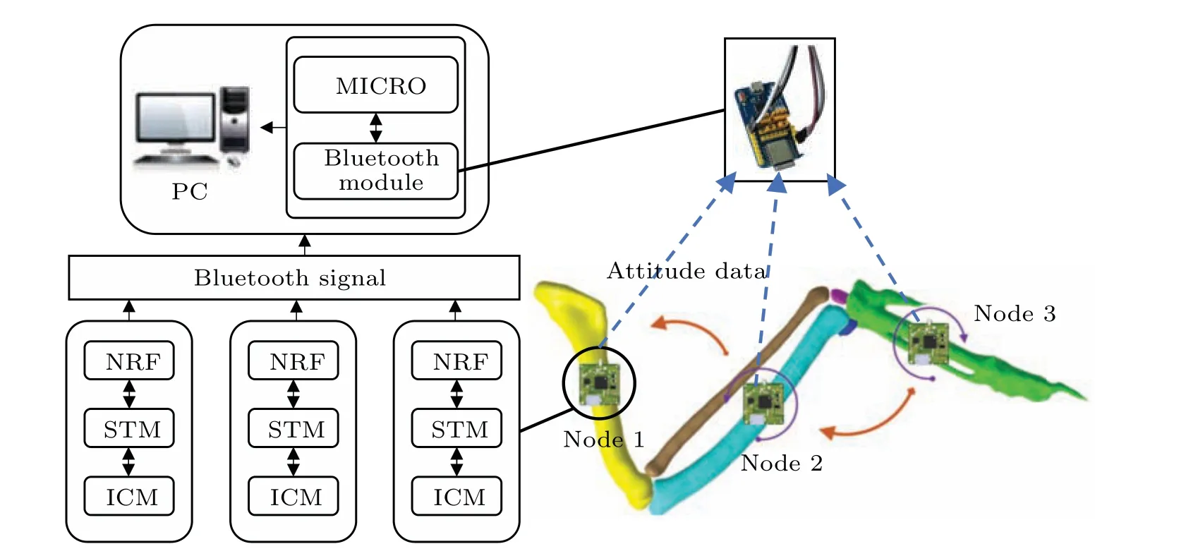
Fig.3.System block diagram and 3D skeleton.Sensor nodes are installed on the 3D-printed bionic bone.
3.Measuring methods of the motion capture system
In this section, the capture methods are presented for the motion capture system.Sensor measurement method,calibration method and absolute orientations filter based on quaternion-based extended Kalman filter are described to implement the measurements of each unit.Thereafter, all the nodes are integrated to establish the motion capture system.
3.1.Models of the sensors
To fuse the inertial sensor and magnetic sensor,it is necessary to establish two coordinate systems.The orientations of a rigid body in the space are determined when the axis orientation of a coordinate frame attached to the body frame with respect to the navigation frame is specified.[2]The sensor models to be built include rate gyros,accelerometers,and magnetometers.
Because the MEMS rate gyros do not have enough sensitivity to measure the earth’s angular velocity, the rate gyros model can get rid of the earth’s angular vector.The output signal of a rate gyro is influenced by noise and bias:
whereωmis measured by the rate gyros,ωis the true value,bgis the gyro’bias,andwgis the noise that is supposed to be Gaussian with zero means.
As the accelerometers model, the measurements of accelerometers in the body framebcan be written as follows:
whereamis 3×3 matrixes measured by the accelerometers,Cbndenotes the orientation cosine matrix representing the rotation from the navigation frame to the body frame,ganda ∈R3are the gravity vector and the inertial acceleration of the body,respectively,expressed in the navigation frame,andg=9.81 m/s2denotes the gravitational constant;Mais 3×3 matrixes that scale the accelerometers outputs;bais the vector of accelerometers’bias;wa∈R3is the vector of Gaussian with zero-means.Commonly,the absolute acceleration of the rigid body in the navigation frame is supposed to be weaka ?gor the rigid body is static.Then,the model of accelerometers can be simplified as follows:
As the magnetometers model,the unit vectorHhrepresents the ideal magnetic vector in the navigation frame.The measurements in the body framebare defined
3.2.Extended Kalman filter
White noise,disturbance,etc.,are usually included in the measured data which will affect the accuracy of data.Therefore, calibration and filter design are needed.An extended Kalman filter is designed to estimate the orientation of bird wing bones.This approach has gained a high degree of recognition for vehicle and satellite[15]azimuth estimation, and more recently, MEMS-based IMMS tracking.[16–19]It is advantageous to ordinary extended Kalman filtering because differences in estimated and true orientation are assumed to be much smaller than the actual one,which eventually results in a smaller linearization error.[10]The multiplicative error quaternion method is used,and the error quaternion is represented as an unconstrained vector where the filter acts on the quaternion.Parameterization of the true quaternionqi jis given by
where ˉqijis the nominal quaternion andδqis the error quaternion,⊙is the quaternion multiplication operator.The helix angleδθijcan approximate the error quaternion:
whereθijis the unit vector indicating a rotation axis andδis the magnitude of the rotation around the axis.Filters are deployed at each sensor node.The sensor is updated according to the measured accelerometer,magnetometer and biomechanical dimensional information.The filter uses a general state space model for dynamicsxk+1and measurementsyk:
wheref(xk)denotes the transition function andh(xk)denotes the measurement function.After the sensor status is initialized, the filter receives data from each sensor node and performs an iterative calculation of updates.Measurement updatesyvectorare differentiated from accelerometers and magnetometers, while biomechanical information is represented byybiomech.In each iteration calculation, the Kalman gain is calculated, the error state and its covariance are updated according to Ref.[20].
where the minus and plus sign denote the a-priori and aposteriori estimate respectively,Hdenotes the linearized matrix of the measurement equationh(δx),Iis an identity matrix,Ris the measurement covariance corresponding to the measurement uncertainty,δyis the difference between estimated and measured sensory input.
3.3.Motion capturing system
For bird body structure, the articular wing skeleton can be modelled as a closed chain,originating from the trunk and ending at the carpometacarpus, as illustrated in Fig.4.Hummers, radius, ulnar, and carpometacarpus are included in the wing skeleton.The four main bones are modelled as rigid bones with four sensors mounted on the covered feathers.The trunk sensor lies on the torso dorsal with theXaxis directing ahead, and theYaxis directing from the torso to the wingtip.All the other sensors are placed and aligned with the trunk sensor at the initial state.The relative orientation between the two neighbouring bones can be obtained by solving the following differential equation:
whereqijis the unit quaternion describing the orientation of frameΨjwith respect to frameΨi,[21]andωis the angular velocity of bodyjwith respect toΨiexpressed in frameΨj.The relative angular velocityis determined by subtracting the absolute angular velocity of the two bones.The angular velocity of a single body is measured using a 3D rate gyroscope,[10]whose outputy?can be modelled as
Before measuring the bird’s posture,sensor 1 was fixed on the torso,and sensors,2,3,and 4 were fixed on the left humerus,ulnar,and carpometacarpus,and were as close to the centre of the bone as possible.The increase in the number of sensors is helpful to the improvement of data accuracy to some extent.In this experiment, the size of the sample limits the number of sensors.If it is used for large birds,the number of sensors can be appropriately increased.Similarly, sensor units 5, 6,and 7 were fixed on the right wing.It should be noted that the small size of the radius makes it difficult to be identified by the developed sensor, thus, only ulna motion is measured in the current research.The bird wing is simplified as a set of linked mechanisms, where the humerus is modeled as part 1,the union of radius and ulna are modeled as part 2,and the carpometacarpus is modeled as part 3,as shown in Fig.4.
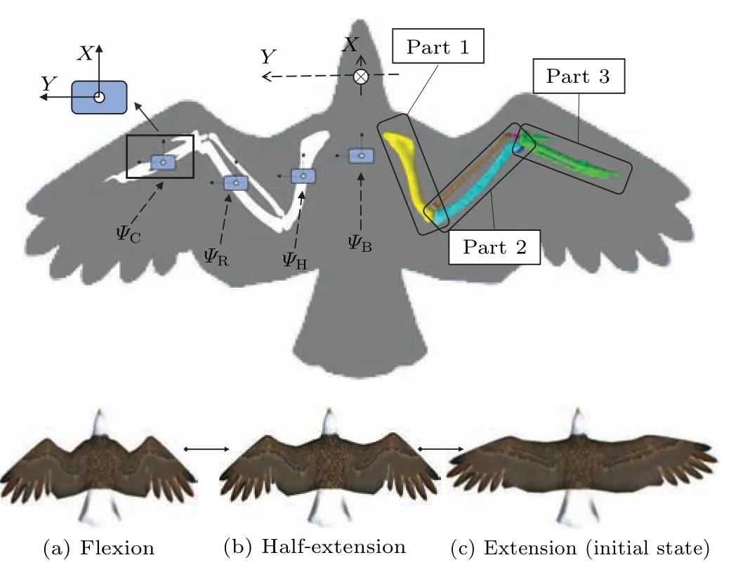
Fig.4.Illustration of sensor arrangement.Sensors are installed on the skin above the humerus(H,part 1),radius(R,part 2),carpometacarpus(C,part 3)and body(B).
3.4.Sensor accuracy verification
To verify the measurement data of the motion capture system,the static angle accuracy and dynamic angle accuracy of the motion capture system were tested.The sensor node was tested on an Instrumentation System TVP-352A with a measuring range of 0°–360°and angular accuracy of±1''.An electronic timer with a deviation of±0.1 s/h was also used for angular accuracy.During the test,the ambient temperature in the laboratory was 21°C and the air humidity was 55%.The sensor was mounted tightly on the testing platform and moved in sync with the platform, as shown in Fig.5.Both the measured data of the sensor and standard data of the TVP-352A were transmitted from the MCU to the computer at the same time.
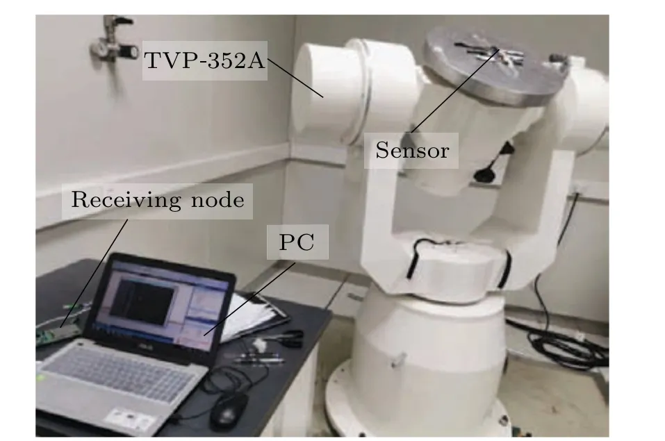
Fig.5.Arrangement of the precision measurement for the developed sensor.

Table 2.Dynamic angle measurement results.
As the angular accuracy test,the sensor was rotated from 0°to 90°,and angular was recorded at 9 critical stations.Deviations of the measured data from the standard data are illustrated in Table 1.It is shown that the maximum deviation is?0.1°.As the angular velocity accuracy test, four test cases were performed under 10.00°/s.A maximum deviation of?0.46°/s was found as shown in Table 2.The maximum deviations of both angular and angular velocity are small and the tested data match with the standard data well.Above all, the accuracy of the developed sensor has been verified.
4.Morphing experiment of a Falco peregrinus
4.1.Experimental arrangement
Motion capture experiments ofFalco peregrinuswere conducted because it is one of the world’s fastest birds.They are strong, fast, and ferocious, they hunt by clenched talons and kill by impact using their high speed and maneuverability.[22]Many investigations have contributed to the avian anatomy of the muscles and bones.[23–26]A carcass ofFalco peregrinuswas donated by the Zhejiang Museum of Natural History as detailed in our previous research.[22]
In our previous studies, bird specimens were carried out in a fixed posture using a CT scan approach.Detailed gestures,including bone shapes, and relative rotations,etc., were all obtained with high precision.However,the previous postures were measured in several discrete positions,and no continuous motions have been obtained.To estimate the wing motions in a continuous manner,the developed motion capture system was used to implement this measurement.The specimen was suspended in a developed suspension system which was detailed in our previous research.[22]Pairs of nylon wires were used to suspend each wing to maintain the exact flying pose.The specimen shapes were manually adjusted to morph under the professional directions of the ornithologists of the Zhongyong Fan team.The flapping and extending movements ofFalco peregrinuswere recorded by each sensor unit,and the corresponding critical postures were also scanned by the CT approach,as shown in Fig.6.The bird wing was simplified as a set of linked mechanism and motions of ulna and carpometacarpus were obtained.After the experiment, the testing bed was cleaned and disinfected to guarantee biosafety.One limitation of this experiment is that the motion of the sample is different from its natural state, only the geometric pose data has reference value, and the dynamic information such as acceleration and frequency cannot be reproduced through the dead body sample.More valuable dynamic information needs to be collected in future studies involving live samples for a more complete understanding.In this regard,experiments have verified the applicability of the developed sensor,and it is planned to be applied to the live motion capture of small birds such as pigeons and parrots.To obtain reliable dynamic data such as acceleration and frequency.

Fig.6.Experimental arrangement of Falco peregrinus.(a)The specimen was suspended in the suspension system with the sensor mounted,(b)critical postures were scanned.
4.2.Extending motion
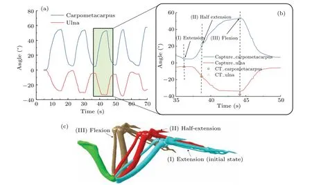
Fig.7.Captured motion and scanned shape of the falcon wing: (a)continuous rotations of ulna and carpometacarpus,(b)scanned bone shape,(c)comparison of scanned angle and captured motion.
The continuous extending motions of theFalco peregrinuswing were recorded, as shown in Fig.7(a).Sinusoidal function appeared in both ulna and carpometacarpus rotations.The roll angle (rotate aroundXaxis) and pitch angle (rotate aroundYaxis)of the skeleton remained almost the same during the extension.Rotation around theZaxis is the main factor to change the wing shape.Only a minus rotation was found for the humerus which always fluctuated by the cover feathers.Thus, it was not discussed in the current research.The measurement results show that the motion of the carpometacarpus is the key factor in wing shape during the extending/contracting motion.It is shown that the extreme rotation of the ulna is?35.1°and the one of carpometacarpus is 57.7°.During extension, three critical postures, extension,half-extension and extraction, were also scanned by CT approach, as shown in Fig.7(c).Thereafter, the orientation of each bone was extracted from the scanned shape and then compared in Fig.7(b).It is shown that the two results are consistent with each other, and the validity of the measured data is verified.
4.3.Flapping motion
A typical flapping motion ofFalco peregrinuswas discussed in the current research.A three-jointed arm system is usually adopted for avian wing geometry and kinematic analysis.However, the cover feathers were stacked up and the orientation of the sensor above the humerus severely fluctuated when the wing was fully contracted.Thus, a discussion about humerus motion was not presented, and a simple double-jointed arm system was used to estimate wing flapping motions as shown in Fig.8(a).In detail, the humerus, radius and ulna were integrated as arm 1,while the carpometacarpus was simplified as arm 2.The study focused on rotations of arm 1 and arm 2 which reflected the manoeuvre ring motions of theFalco peregrinus.On the other hand, no experimental motion data has ever been reported for natureFalco peregrinus.Tianshu Liu once extracted and estimated the flapping wing movement data of the seagull by optical means.[27]In consideration that the body length, weight, and wingspan ofFalco peregrinusare similar to those of a seagull,the motions of theFalco peregrinuswere compared according to the seagull’s motions.[27]
During the test, the wing shape ofFalco peregrinuswas found to change dramatically during a flapping cycle, which was mainly contributed by the rotation of the shoulder joint,the angle between the ulna and carpometacarpus was also found to oscillate with an impressive amplitude.The recorded periodic movements ofFalco peregrinuswere consistent with those of the seagull as well as each bone.In downstroke,the wing extends as far as possible to attain a large surface which is beneficial to promote more air.During the downstroke, more lift and thrust were generated to resist gravity and drag.As the wing was raised during the upstroke, the carpometacarpus was slightly contracted towards the torso to reduce the surface area and minimize air resistance.[28]
Based on the experimental results, the established raptor model was used to restore the wing posture.Figure 9 illustrates the changes in flapping wing attitude over one cycle.By coupling the data to the model,we can directly observe the posture of the wings when they flutter.During the downstroke,the wings are extended as far as possible to expand the wing area, and secondary flight feathers are stacked in sequence to cover the trailing edge of the wings, which helps to increase the lift and thrust obtained.During the upstroke, the wing humerus and ulna(arm 1)lift first,while the carpometacarpal(arm 2) folds downward and contracts inward.When arm1 lifts near the highest point, arm 2 lags behind arm 1 and extends.At the same time,the gap between the secondary flight feathers is enlarged, which increases the air leakage rate during the upstroke.Therefore, the air resistance during the upstroke is greatly reduced.Thanks to a series of variants, the wings gain lift and sustained thrust for flight during the entire flapping cycle.

Fig.9.Raptor model and flapping posture recovery.
5.Conclusion
No wing motion experiment has been reported for natureFalco peregrinuswhich is critical for studying bird flights and bionic design.Thus,a novel tinny motion capture system was developed for birds, and wing motions of aFalco peregrinuswere recorded.In this study,we evaluated the performance of the sensors as well as the flight attitude of the peregrine falcon.
Both hardware and software of measurement sensor that is made up of micromachined gyroscopes,accelerometers,and magnetometers have been designed and implemented.The measured data of each sensor node is fused to obtain quaternions based on an extended Kalman filter and then transmitted to the hub node using a Bluetooth module.All the nodes are integrated to establish the motion capture system with high accuracy verified on an instrumentation system TVP-352A.
Thereafter, wing motions of aFalco peregrinuswere measured using the developed motion capture system.The extending/contracting motions were recorded in a continuous manner to study the morphing process from cruising to diving.Three critical postures of the wings,extension,half-extension and extraction were verified using a CT scan approach.Then,the flapping cycles of the falcon were also studied based on a two-jointed arm model.Combined with the model and data,the flapping wing cycle was reconstructed, and the causes of high and low lift in the process of peregrine falcon flapping were verified.The results of the motion capture experiment meet the expected standards.Therefore,the lightweight IMMU-based motion capture system is considered suitable for the movement data collection of living birds such as pigeons and parrots.The next stage is to test motion capture on live pigeons with the capture system developed.This helps to advance the study of the flight mechanism of birds and can be mutually verified with optical motion capture methods.
The attitude capture system designed in this article is available in the future of the natural action of birds.In addition,the wing kinematics given in this paper can be used for the preliminary design of flapping MAVs, and they provide a foundation for further experimental and computational studies to understand the aerodynamic aspects of flapping flight.
Acknowledgements
Project supported by the National Natural Science Foundation of China (Grant Nos.52175279 and 51705459), the Natural Science Foundation of Zhejiang Province, China(Grant No.LY20E050022),and the Key Research and Development Projects of Zhejiang Provincial Science and Technology Department(Grant No.2021C03122).
- Chinese Physics B的其它文章
- High responsivity photodetectors based on graphene/WSe2 heterostructure by photogating effect
- Progress and realization platforms of dynamic topological photonics
- Shape and diffusion instabilities of two non-spherical gas bubbles under ultrasonic conditions
- Stacking-dependent exchange bias in two-dimensional ferromagnetic/antiferromagnetic bilayers
- Controllable high Curie temperature through 5d transition metal atom doping in CrI3
- Tunable dispersion relations manipulated by strain in skyrmion-based magnonic crystals

