Disturbances rejection optimization based on improved two-degreeof-freedom LADRC for permanent magnet synchronous motor systems
Chenggang Wang, Jianhu Yan, Wenlong Li, Liang Shan, Le Sun
School of Automation, Nanjing University of Science and Technology, Nanjing 210094, China
Keywords:Permanent magnet synchronous motor(PMSM)Active disturbance rejection control (ADRC)Disturbance observer Two-degree-of-freedom control Anti-disturbance
ABSTRACT Permanent magnet synchronous motor (PMSM) speed control systems with conventional linear active disturbance rejection control (CLADRC) strategy encounter issues regarding the coupling between dynamic response and disturbance suppression and have poor performance in suppressing complex nonlinear disturbances.In order to address these issues,this paper proposes an improved two-degree-offreedom LADRC(TDOF-LADRC)strategy,which can enhance the disturbance rejection performance of the system while decoupling entirely the system's dynamic and anti-disturbance performance to boost the system robustness and simplify controller parameter tuning.PMSM models that consider total disturbances are developed to design the TDOF-LADRC speed controller accurately.Moreover, to evaluate the control performance of the TDOF-LADRC strategy, its stability is proven, and the influence of each controller parameter on the system control performance is analyzed.Based on it, a comparison is made between the disturbance observation ability and anti-disturbance performance of TDOF-LADRC and CLADRC to prove the superiority of TDOF-LADRC in rejecting disturbances.Finally, experiments are performed on a 750 W PMSM experimental platform, and the results demonstrate that the proposed TDOF-LADRC exhibits the properties of two degrees of freedom and improves the disturbance rejection performance of the PMSM system.
1.Introd uction
Permanent magnet synchronous motor (PMSM) has received significant attention in various fields, including transportation systems, aerospace, and geographical explorations, because of its simple structure, high torque density, high efficiency, and affordable costs [1,2].In mainstream PMSM drive systems, the proportional-integral (PI) controller has been applied widely [3].However, as a single-degree-of-freedom controller, any parameter changes in the PI controller will simultaneously affect the system's dynamic performance and disturbance rejection performance,resulting in a complex controller parameter tuning process [4].Additionally, an excessive feedback error can induce saturation in the integral component of the PI controller, resulting in output fluctuations and potential system destabilization [5].Considering the disturbances such as electrical parameter mismatches,magnetic saturation, dead zone voltage, and current sampling errors in the PMSM system, it is challenging for the PMSM control system based on the PI controller to meet the requirements of eminent robustness and high precision [6].
Aiming to enhance the anti-disturbance performance of PMSM control systems, numerous anti-disturbance strategies, such as disturbance observer-based control (DOBC), disturbance adaptive control (DAC), equivalent input disturbance (EID), and active disturbance rejection control (ADRC), were introduced [7,8].Among these strategies, ADRC, proposed by Han, exhibited excellent disturbance suppression performance and model-free characteristics, making it highly suitable for PMSM systems [9].Han regarded the controlled object's internal,external,and unmodeled disturbances as total disturbances.In order to dispel these disturbances, a nonlinear extended state observer (NESO) was proposed to estimate them in real time and eliminate them in the control law[10].It was evident that the NESO plays a key role in nonlinear ADRC, so improving the observer's estimate capacity(ability) was critical to enhancing the control performance of the ADRC strategy.In Ref.[11],a modified ADRC strategy based on cascaded NESO was proposed by L.Zhu et al.and successfully applied to the PMSM sensorless control system,which effectively enhanced the system's capability to suppress load disturbances.In Ref.[12], Q.Hou et al.introduced the finite-time technique to improve NESO, which improved the robustness while maintaining the noise rejection capability of the system.
The nonlinear ADRC strategy exhibited excellent disturbance rejection performance but was limited in industrial applications due to its numerous parameters and complex tuning[13].To tackle these challenges, Z.Gao et al.proposed the linear extended state observer (LESO), which formed the theory of linear active disturbance rejection control (LADRC), commonly referred to as conventional LADRC(CLADRC)[14].The CLADRC strategy preserves the model-free property of the nonlinear ADRC strategy and reduces the complexity of controller parameter tuning through the bandwidth scale method, facilitating its digital implementation [15].However,LESO was limited to providing error-free observations for constant or slowly varying disturbances, which restricted its applicability in systems with high-frequency or higher-order function disturbances [16].Although increasing the bandwidth of the LESO can effectively reduce observation errors,it also amplifies the impact of sampling noise on control performance [17].In addition,the PMSM system with CLADRC strategy failed to achieve complete decoupling of dynamic and anti-disturbance performance, where changing the proportional controller gain will simultaneously impact both aspects[18].Therefore,achieving rapid dynamic response and steady-state accuracy in practical applications required a complex controller parameter tuning process[19].
To address the issue of undesirable anti-disturbance performance in CLADRC, various advanced control strategies, including adaptive control,fuzzy control,and sliding mode control,have been integrated with the LADRC strategy, resulting in the proposal of numerous improved LADRC strategies [20-22].These enhanced LADRCs strengthened the system's disturbance rejection ability but did not modify the structure of LESO, so they could not fundamentally solve the existing issues in the CLADRC strategy.In Ref.[23], a cascaded LESO was proposed to realize error-free observation of ramp disturbances but still exhibits significant static observation error when observing higher-order power function disturbances.In Ref.[24], a higher-order ESO was introduced,effectively improving the system's robustness.Compared to the LESO, the higher-order ESO has enhanced observation capability for time-varying disturbances, but it faced challenges due to its susceptibility to sampling noise.L.Feng et al.introduced a variable gain LESO (VGLESO) to utilize disturbance observation capability fully.However, the parameter tuning for VGLESO is significantly more challenging than LESO [25].
Considering the analysis conducted above, although numerous studies have discussed various methods for improving LADRC control performance, few focused on enhancing the disturbance rejection capability of LADRC while achieving a complete decoupling of dynamic performance and disturbance rejection performance.However,researching an improved LADRC with prominent disturbance rejection performance and two-degree-of-freedom(TDOF) characteristics is significant to building PMSM control systems with a fast dynamic response and excellent disturbance rejection.Therefore,this paper proposes an improved two-degreeof-freedom LADRC(TDOF-LADRC) strategy to completely decouple the system's dynamic response and disturbance rejection performance while enhancing its anti-disturbance capability.To overcome the insufficient disturbance observation capability of the LESO, an improved LESO (ILESO) that incorporates a correction function is proposed to achieve a more accurate observation of complex nonlinear time-varying disturbances.Moreover, the dynamic response performance of the PMSM speed control system with the TDOF-LADRC speed controller is solely determined by the proportional controller gain, while the anti-disturbance performance solely relies on the observer bandwidth.Thus,the ILESO and the control law of TDOF-LADRC can be adjusted independently to reduce the challenges with tuning controller parameters and enhance the system's flexibility.Furthermore, the experimental results demonstrate that the proposed TDOF-LADRC strategy exhibits excellent robustness and further enhances the disturbance rejection performance of the PMSM system.
The remaining sections of this paper are organized as follows:Section 2 presents the design process of the TDOF-LADRC speed controller.Section 3 analyzes the control performance of the TDOFLADRC, demonstrates its stability, and compares it with CLADRC.Experiments are presented in Section 4.Finally,Section 5 provides the conclusion for this paper.
2.PMSM speed control system based on TDOF-LADRC
2.1.PMSM mathematical model with total disturbances
In the PMSM speed control system, various disturbances occur during their operation to reduce the performance of the speed controller.According to the source of the disturbances in the system, it can be classified into internal disturbances, external disturbances, and unmodeled disturbances, as illustrated in Fig.1.Typical nonlinear disturbances in the PMSM system include cogging torque Tcogand friction torque Tfs.Additionally, PM flux harmonics Δψfalso cause the disturbance torque Tflux, whereas sampling errors from current sensors result in the disturbance torque TA.Furthermore, other undesirable factors such as deadzone voltage, parameter mismatch, and inverter nonlinearity can generate unmodeled dynamics fM, thereby directly affecting the operational performance of the PMSM.
Taking all these disturbances into account, the PMSM mathematical model can be formulated as follows

Fig.1.Categories of PMSM system disturbances.
where, t is the time variable; idand iqare the d-axis and q-axis stator currents;udand uqare the d-axis and q-axis stator voltages;θeis the electrical angle;θmis the mechanical angle;Rsis the stator resistance; Ldand Lqare the d-axis and q-axis stator inductances,for surface-mounted PMSM (SPMSM) Ld=Lq=Ls; ψfis the flux linkage; ωmis the rotor speed; J is the inertia of motor; Pnis the number of pole pairs; ktis the electromagnetic torque coefficient;when the PMSM system adopts the field-oriented control (FOC)scheme with idref=0,kt=1.5Pnψf;Bvis the frictional coefficient;Teis the electromagnetic torque; TLis the load torque; b0=kt/J is the intrinsic system constant; f is the total disturbances.
2.2.TDOF-LADRC design
Let y(t) = ωm(t), u(t) = iq(t), x(t) = [x1(t) x2(t)]T=[y(t) f(t)]T.Considering the total disturbance f(t)in Eq.(1)as an extended state variable, the mechanical dynamics of the PMSM with the total disturbances can be expressed as [26]
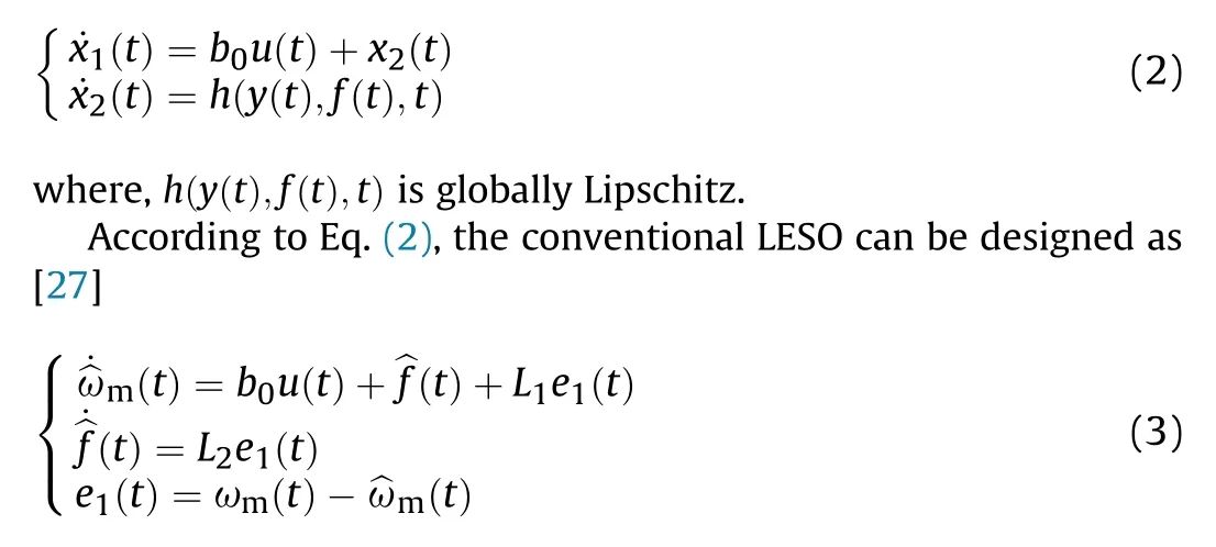
where the observation value is represented by the symbol "^"; L1and L2are the observer gains,the integral value of e1(t)is regarded as the observation of total disturbances.Insufficient observer gains can decrease the convergence speed of LESO and lead to noticeable observation errors.Nevertheless, excessive observer gains can result in integration saturation that causes the observer to diverge.Additionally,the integrated term only focuses on speed observation error and neglects some factors like acceleration,which are directly related to disturbance torques.Consequently, conventional LESO demonstrates inadequate capability in observing uncertain timevarying nonlinear disturbances.Furthermore, conventional LESO does not consider L1e1(t) as a fraction of the disturbance observations.Although this approach effectively prevents output oscillations, it fails to entirely eliminate the total disturbances while tracking the time-varying reference signal.Hence,it is necessary to improve CLADRC's performance in disturbance rejection.
In order to achieve accurate observation of uncertain nonlinear time-varying disturbances,a compensated disturbance observation term, denoted as ?f(t), has been incorporated in the design of the observer.According to Eq.(2), the following observer can be designed to observe ωmand f.
where L1is the observer parameter that requires tuning.When^ωm(t) tracks ωm(t) closely, ?f(t) will also track f(t) closely, which indicates that ?f(t)is also the observation of f(t).Consequently,?f(t)is referred to as the compensated disturbance observation term.Subtraction of Eqs.(2) and (4) produces that,
where,e2(t) = f(t)-?f(t).
According to Eq.(5),the observation error and fluctuation rate of the ^ωm(t)are directly impacted by the e2(t).For optimal reduction of observation error and fluctuation, ?f(t) should observe f(t) as precisely as possible.
Given that both ?f(t)and^f(t)are observations of f(t),a correction function denoted as D(s) can be employed to establish the connection between them,
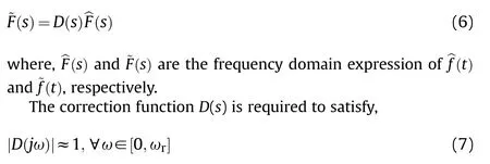
where ωris the highest frequency selected for disturbance estimation.
The low-pass filter D1(s)=β/(β+s)is a typical correction function that connects ?f(t) and ^f(t), where β denotes the filter coefficient proportionate to the cutoff frequency[28].However,when the total disturbance frequency exceeds the cutoff frequency, the observation value of disturbance exhibits amplitude attenuation and phase lag.Consequently,the low-pass filter cannot efficiently accomplish the connection task.In order to address this problem,an improved correction function D2(s) is devised,

Fig.2.Bode diagrams of D1(s) and D2(s).
where,Tfrepresents the time constant of the correction function.
Fig.2 illustrates the bode diagrams of low-pass filter D1(s) and improved correction function D2(s).It can be observed from Fig.2 that the D2(s) exhibits neither attenuation nor phase lag over a considerable frequency range.Therefore,D2(s)is better suited as a correction function.
By combining Eqs.(4), (6) and (8), the expression of the LESO with the improved correction function (ILESO) is as follows
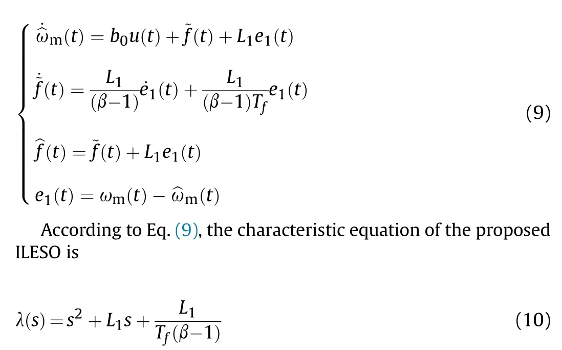
Using the bandwidth method,Eq.(10)is set as λ(s) = (s+ωo)2,and both poles of the ILESO are set as -ωoat this time [14].By equating the corresponding coefficients on both sides of the equation,the parameters of ILESO can be simplified as follows:L1=2ωo, Tf= 1/ω3o,β= 2ω2o+ 1.When ωo>1, Tf<1 and β>1 are established.Notably,ωois the sole parameter that requires tuning, representing the observer's bandwidth.
Let z1(t) = ^ωm(t),z2(t) =?f(t),z3(t) =^f(t),e1(t) = x1(t)-z1(t),e2(t) = x2(t)- z2(t), Eq.(9) can be reformulated as
Subsequently, the observations are utilized for the implementation of the linear state error feedback (LSEF), which is expressed as
where,kpis the controller gains;ωmref(t) is the reference speed.
According to Eqs.(11)and(12),the block diagram of the PMSM control system, which is based on the FOC scheme with the proposed TODF-LADRC, is shown in Fig.3.The PMSM control system utilizes the cascade dual closed-loop structure that consists of the current loop and the speed loop.The proposed TDOF-LADRC generates the q-axis reference current iqrefin the speed loop,while the current loop utilizes PI controllers to generate the dq-axis reference voltages.
3.Performance analysis of the TDOF-LADRC
3.1.Analysis of stability
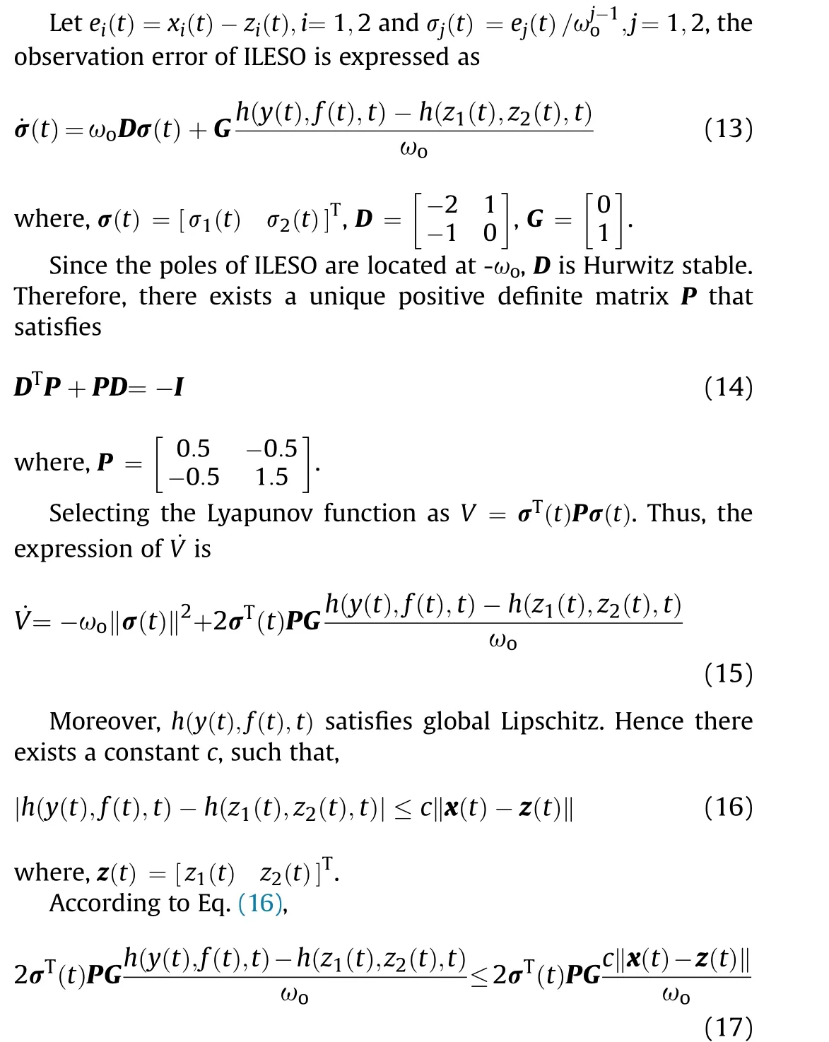
Besides, Eq.(18) is established when ωo≥1.
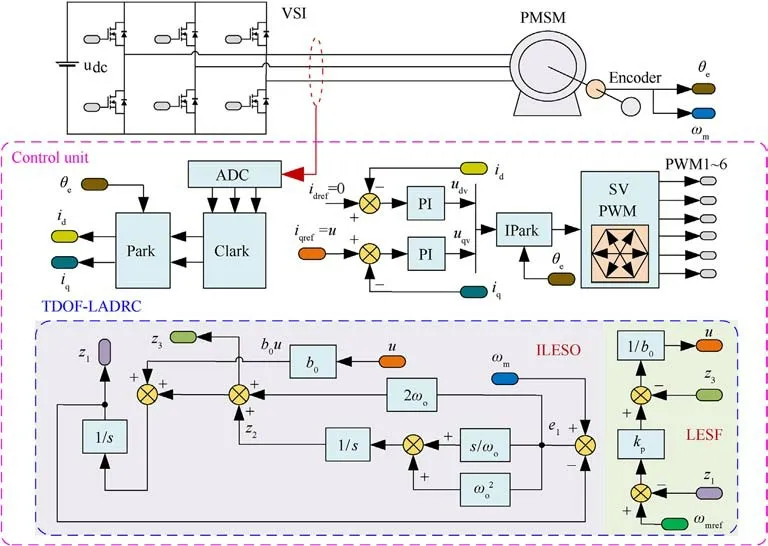
Fig.3.Block diagram of the FOC-based PMSM system with the proposed TDOF-LADRC.
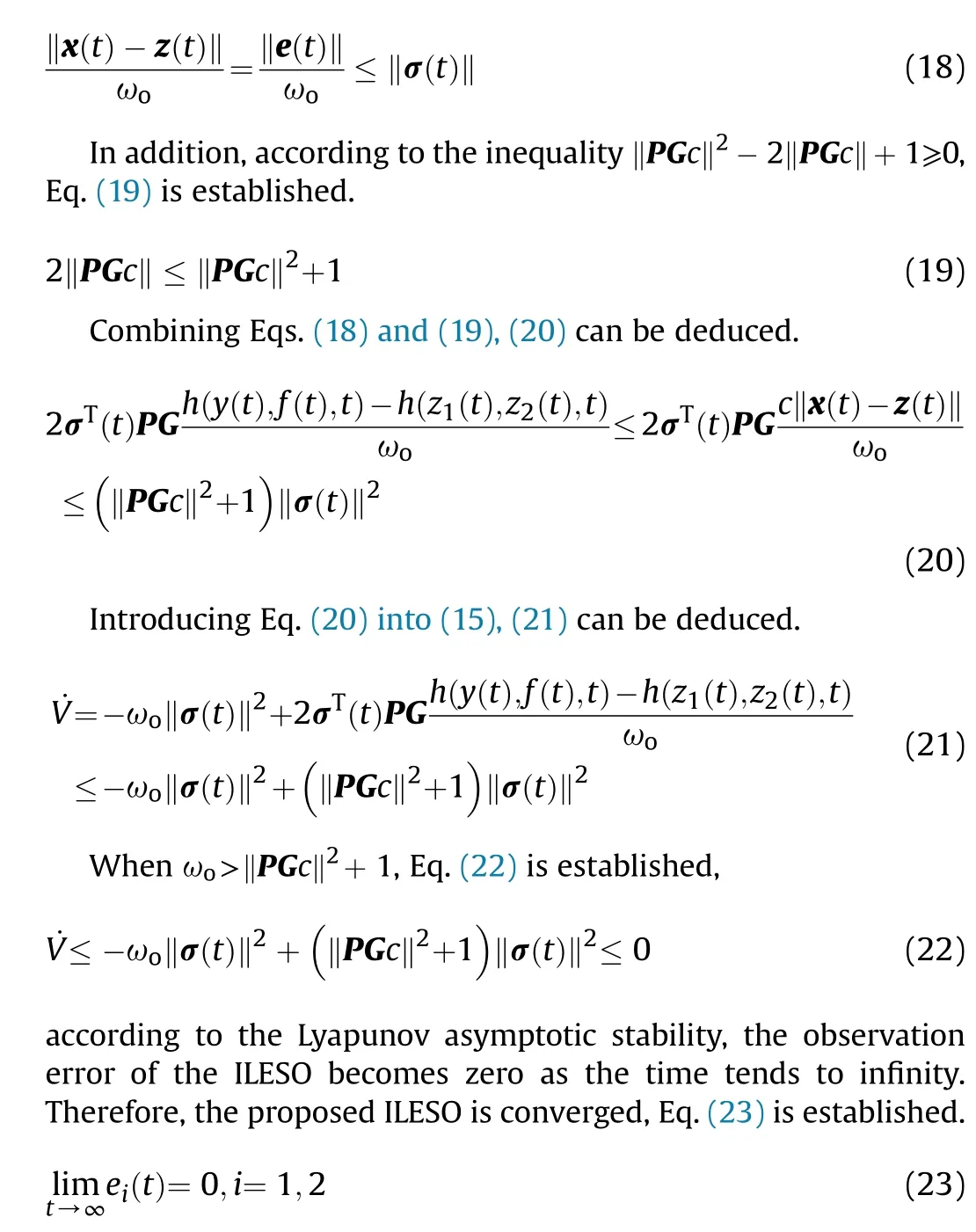
Assume that the primary aim of controller design is to ensure the output of the controlled object tracks a bounded reference signal r(t)whose derivatives are bounded.From Eqs.(12) and (24)can be obtained,

3.2.Proof of two-degree-of-freedom characteristics
Applying the Laplace transform in Eq.(11), the frequency domain expression of the ILESO is,

Combining Eqs.(25)and(12),the output of the TDOF-LADRC can be deduced as
where,Λ4=ω3o+ 2kpω2o+ kp.
In PMSM control systems, the current controller typically exhibits a faster dynamic response than the speed controller.When the response of the current controller is sufficiently fast, the dynamic process of the current is negligible, so the controlled object of the speed controller is the PMSM mechanical dynamics model[3].In order to simplify the analysis process,it is assumed that the current controller in the PMSM system responds quickly enough.According to Eqs.(26)and(2),the PMSM speed closed-loop system based on TDOF-LADRC can be restructured as Fig.4 [26].
In Fig.4,the total disturbances f,reference signal r,and sampling noise δnare all external inputs,while y represents the output of the closed-loop system.In order to analyze the impact of a specific external input on output y,other external inputs can be set as zero,and then the analysis can be performed using the deduced transfer function [27].Furthermore, since the total disturbances f includes all nonlinear components and parameter perturbations in the system,the closed-loop system is a linear system[26].According to the superposition principle, the overall output of the closed-loop system is the algebraic sum of the responses caused by each external signal acting independently.Therefore,according to Fig.4,the transfer functions between the output y and each external input, as well as the expression for y, can be represented as
where,Gr(s)characterizes the system's dynamic performance,Gf(s)characterizes the anti-disturbance performance of the system,and Gn(s) characterizes the noise suppression performance of the system.

Fig.4.The restructured block diagram of TDOF-LADRC.
It can be seen from Eq.(27) that Gr(s) only contains the proportional controller gain kp, while Gf(s) is only related to the observer bandwidth ωo.Besides, the Gn(s) is only impacted by the observer bandwidth ωoand independent of the kp.This distinctive characteristic indicates that the dynamic performance depends solely on the parameters kpand is independent of the observer bandwidth, while the disturbance rejection performance solely depends on the parameters ωoand is independent of the parameters of kp.Therefore, the LESF and ILESO of TDOF-LADRC can be tuned independently, which eliminates the requirement for the complex controller parameter tuning process in CLADRC to facilitate the attainment of both rapid response and accurate motion concurrently.Overall, the proposed TDOF-LADRC is a two-degreeof-freedom controller that completely decouples the dynamic performance and disturbance rejection performance.
3.3.Relationships between controller parameters and control performance
In order to evaluate the impact of different controller parameters on the control performance of TDOF-LADRC, bode diagrams were generated for Gf(s) and Gn(s) under various ωoconditions,along with Gr(s)under different kpconditions,which are presented in Fig.5.
As depicted in Fig.5(a), the tracking performance of TDOFLADRC can be improved with an increase in the value of kp.Similarly, Figs.5(b) and 5(c) reveal that the low-frequency disturbance rejection performance of TDOF-LADRC improves as ωoincreases.However, Fig.5(c) demonstrates that increasing ωoamplifies the influence of sampling noise on the system's control performance.It is also worth noting that enormous kpvalues can result in overshoot during startup and, in severe cases, lead to fearful oscillations.Therefore, it is crucial to select appropriate values for the parameters ωoand kpbased on the specific control performance requirements of the system rather than mindlessly increasing their values.
3.4.Comparison of disturbance observation capability between ILESO and LESO
In order to assess and compare the disturbance observation capabilities of ILESO and LESO,it is necessary to derive the transfer function that describes the relationship between the disturbance observation error and the disturbance.
Let the ILESO's disturbance observation error is ef(t) = f(t)-z3(t).By combining Eqs.(2) and (11), the transfer function that describes the ILESO's disturbance observation performance,Gef1(s),can be deduced as
Moreover,from Ref.[27],the transfer function that describes the LESO's disturbance observation performance, Gef2(s), can be expressed as
According to the inverse Laplace transformation theorem, the disturbance observation error expressions for ILESO and LESO can be derived from Eqs.(28) and (29), respectively.

Fig.5.Bode diagrams of Gr(s), Gf (s), and Gn(s): (a) Gr (s); (b) Gf (s); (c) Gn(s).
where φ1(t) and φ2(t) are the disturbance observation error expression of ILESO and LESO,respectively.Besides,φ1(t)and φ2(t)are only related to t and ωo.
Four different typical disturbances are selected with ωo∈[100,400] and t∈[0, 0.1]: a constant disturbance f (t)=1, a ramp disturbance f (t)=t, a quadratic disturbance f (t)=0.5t2and a periodic disturbance f (t)=sin(20πt).The surfaces of φ1(t) and φ2(t) with different disturbances are shown in Fig.6 to compare the observation capability of the two observers.
From Fig.6(a), with the same ωo, both ILESO and LESO can achieve error-free observation for the constant disturbance,but the ILESO converges faster.As can be seen from Figs.6(b)and 6(c),the LESO fails to achieve error-free observation of the ramp and quadratic disturbances.While increasing ωocan reduce the observation error, it cannot eliminate it, and the error increases significantly over time.In contrast,the proposed ILESO can realize errorfree observation for the ramp and quadratic disturbances.Moreover, from Fig.6(d), it can be seen that the ILESO has a minor observation error for periodic disturbances, which exhibits its superior disturbance observation capability compared to LESO.
In order to compare the observation capabilities of LESO and ILESO for different frequency disturbances,ωo=100 is selected,and the Bode diagrams of Gef1(s) and Gef2(s) are plotted, as shown in Fig.7.Fig.7 indicates that the ILESO can observe disturbances without static error across a wider frequency range, proving that ILESO exhibits a superior observational capacity for disturbances in the high-frequency range.
According to the above analysis,it is evident that the ILESO has a more precise disturbance observation capability,and it can achieve error-free observation of some disturbances that cannot be accurately observed by the LESO,which verifies the superiority of ILESO in observing complex disturbances.
3.5.Comparison of anti-disturbance performance between TDOFLADRC and CLADRC
The effects of various types and frequencies of disturbances on the output of two closed-loop systems, namely TDOF-LADRC and CLADRC,are compared to demonstrate the superior ability of TDOFLADRC in suppressing complex nonlinear time-varying disturbances.
According to Ref.[29], the transfer function that describes the relationship between the output y and the total disturbances f in the CLADRC closed-loop system is,

where yFI1(t) and yFI2(t) represent the output responses of the closed-loop systems TDOF-LADRC and CLADRC affected by the total disturbances f, respectively.Besides, yFI1(t) and yFI2(t) are only related to t and ωo.
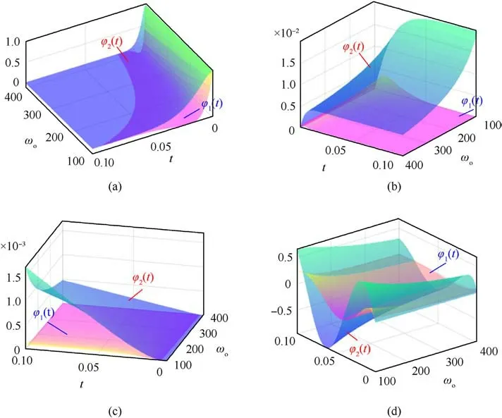
Fig.6.Surfaces of φ1(t) and φ2(t) with different disturbances: (a) f (t) = 1.(b) f (t) = t.(c) f (t) = 0.5t2.(d) f (t) = sin(20πt).

Fig.7.Bode diagrams of Gef1(s) and Gef2(s).
Four typical time-varying disturbances, identical to those described in subsection 3.4, are selected for comparing the disturbance rejection performances between the TDOF-LADRC closedloop system and the CLADRC closed-loop system under various disturbances.In order to ensure fairness,performance comparisons are carried out under conditions where the characteristic equations of both systems are identical.Thus, the controller parameters are configured as kp=50 and ωo∈[100, 400].Fig.8 shows the surfaces of yFI1(t) and yFI2(t) under various disturbances.
It can be seen from Fig.8 that while CLADRC can effectively suppress constant disturbances, it fails to achieve complete suppression of time-varying disturbances such as ramp disturbances and quadratic disturbances.Moreover, quadratic disturbances result in a progressively increasing output error in the closed-loop system of CLADRC.In comparison to CLADRC, the closed-loop system of TDOF-LADRC completely suppresses ramp disturbances and considerably mitigates the effect of quadratic disturbances on the system's output, showcasing its more substantial capability in suppressing time-varying disturbances.While TDOF-LADRC cannot completely eliminate the system's output response caused by periodic disturbances, it exhibits a significantly smaller fluctuation amplitude than CLADRC's.Consequently, the comparative results demonstrate that the TDOF-LADRC strategy achieves a superior level of disturbance suppression, leading to a substantial enhancement in the disturbance rejection performance of the PMSM system.
Then, TDOF-LADRC and CLADRC anti-disturbance performance for different frequency disturbances is compared.According to Eqs.(27)and(31),selecting ωo=200 and kp=100,the comparison results for the disturbance rejection performance of TDOF-LADRC and CLADRC under varying frequency disturbances are shown in Fig.9.From Fig.9,it is evident that TDOF-LADRC and CLADRC have similar capabilities in suppressing high-frequency disturbances when subjected to the same observer bandwidth condition.However,TDOF-LADRC outperforms CLADRC in suppressing low-frequency disturbances.In conclusion, TDOF-LADRC achieves complete decoupling of dynamic and disturbance rejection performance and superior disturbance rejection capabilities.
4.Experimental results and analysis
In order to validate the effectiveness and theoretical analysis of the proposed TDOF-LADRC, an experimental platform, as depicted in Fig.10, is established.The experimental platform comprises PMSM, motor driver, DC power supply, magnetic powder brake,oscilloscope, current probe, DSP emulator, serial-USB communication device,and host computer.The PMSM serves as the controlled object, and its specific parameters are listed in Table 1.The motor driver operates at a power supply voltage of 48 V and utilizes the TMS320F28335 as the processor.Lastly,the magnetic particle brake is employed to apply load to the PMSM.
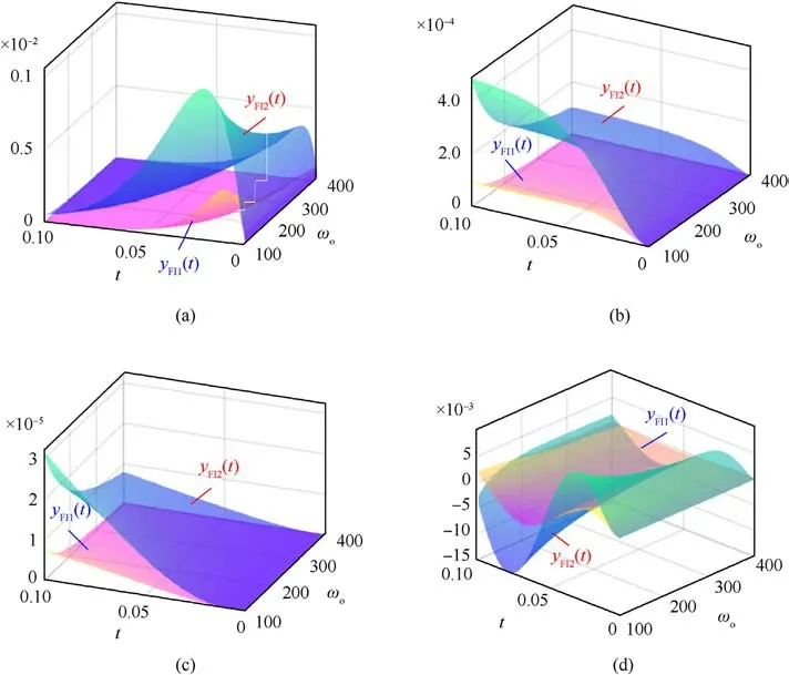
Fig.8.Surfaces of yFI1(t) and yFI2(t) with different disturbances: (a) f (t) = 1.(b) f (t) = t.(c) f (t) = 0.5t2.(d) f(t) = sin(20πt).

Fig.9.Disturbance rejection comparison of CLADRC and TDOF-LADRC.
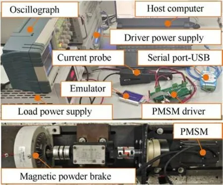
Fig.10.PMSM experimental platform.
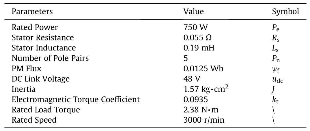
Table 1 Main PMSM parameters.
The PMSM control system operates on idref=0 FOC scheme.The power MOSFET, BSC0702LS, is selected as the switching device for the three-phase voltage source inverter (VSI), and the DRV8301 is utilized as its driver chip.Phase current sampling is facilitated using the DRV8301's internal integrated current shunt amplifiers.Both the sampling and VSI switching frequencies are maintained at 10 kHz.The PI controller, employed for current control, is configured with kp=12 and ki=360.The TDOF-LADRC and CLADRC strategies are used respectively for the speed control to evaluate their control performance.

Fig.11.Step response experimental results: (a) Speed; (b) Q-axis current; (c) D-axis current.
4.1.Step response experiments
Step response experiments were conducted to compare the dynamic performance of TDOF-LADRC and CLADRC using identical controller parameters.The speed controller parameters for TDOFLADRC and CLADRC are kp=50, ωo=100, and b0=603.18.At 0.2 s,the program starts with an initial reference speed ωrefof 2000 r/min, which then transitions to 3000 r/min at 2.2 s and changes to 1500 r/min at 6.2 s.The PMSM operates under no-load conditions throughout the experiment,and experimental results are depicted in Fig.11.According to Fig.11, the PMSM system with the TDOFLADRC method can accurately track ωrefwithout overshooting,demonstrating that the TDOF-LADRC speed controller exhibits excellent dynamic response performance.
Notably,the ILESO considers L1e1(t)as a component of the total disturbance observation ^f(t).Therefore, at the moment of sudden reference speed change,^f(t)exhibits a spike,resulting in a spike in the output of the TDOF-LADRC speed controller, namely iqref, ultimately leading to a spike in the q-axis current response of the PMSM system.In practical applications, if it is necessary to eliminate the spike in the q-axis current response,it can be achieved by appropriately adjusting b0or smoothing the step reference speed by adding the tracking differentiator(TD).
4.2.Load experiment results
Next, the load experiment is conducted to compare the disturbance rejection performance of TDOF-LADRC and CLADRC,and the experimental results are presented in Fig.12.The ωrefis set to 3000 r/min,and the TDOF-LADRC and CLADRC speed controllers are configured with kp=50, ωo=100, and b0=603.18.The PMSM system starts in an unloaded state, and the program execution begins at 0.2 s.At 4.0 s, the magnetic powder brake applies a load torque, as shown in Fig.12(b), to the PMSM system.
Fig.12 indicates that the response time of the PMSM system,from a standstill to the rated speed, is approximately 0.25 s.Moreover,in terms of load disturbance rejection,the speed drop of CLADRC amounts to 77.52 r/min,whereas the speed drop of TDOFLADRC is only 45.66 r/min.Compared to CLADRC,TDOF-LADRC has a 41% reduction in speed drop.Consequently, TDOF-LADRC more effectively preserves the system's speed stability compared to CLADRC and significantly improves the PMSM system's disturbance rejection performance.
The phase-A current waveforms of the PMSM system using CLADRC and TDOF-LADRC are shown in Figs.12(d) and 12(e),respectively, at a speed of 3000 r/min.A comparison between Figs.12(d) and 12(e) clearly reveals there are certain levels of harmonic distortion in the phase-A current for the PMSM system using CLADRC.These harmonics can result in PMSM heating, leading to deviations in parameters like inductance and resistance from their standard values, which reduces the operational performance and efficiency of the PMSM system.In contrast,the PMSM system using TDOF-LADRC reduces harmonic distortion in the phase-A current.To further evaluate the effect of different speed controllers on current quality,a fast Fourier transform(FFT)analysis is conducted on the phase-A currents of each system.The corresponding results are presented in Figs.12(f) and 12(g).Comparing Figs.12(f) and 12(g) reveals that the TDOF-LADRC-based PMSM system exhibits more minor harmonics in each current component than the CLADRC-based PMSM system.Hence, it can be inferred that the TDOF-LADRC speed controller contributes to the improvement of the current quality of the PMSM system.
4.3.Experimental verification of the two-degree-of-freedom characteristic
Fig.13 illustrates the speed response results of the PMSM system employing the TDOF-LADRC speed controller,where the parameter b0is held constant at 603.28,while ωoand kpare varied.In addition,Table 2 displays the setting time from stillness to 3000 r/min and the speed drop when the load applies to the PMSM under different controller parameters.When ωois set to 100, the system's setting times are 0.252 s,0.314 s and 0.426 s for kpvalues of 50,40 and 20,respectively.The corresponding speed drops are 45.66 r/min,44.38 r/min and 45.91 r/min.As kpdecreases, the setting time increases,whereas the speed drop remains nearly unaffected by kp,remaining around 45 r/min.Similarly,with kpset to 50,the speed drops for ωovalues of 100,60 and 30 are 45.66 r/min,74.42 r/min and 146.93 r/min, respectively.The corresponding setting times amount to 0.252 s,0.256 s and 0.261 s.Based on the phenomena,modifying ωoprimarily affects the system's disturbance rejection performance while having minimal impact on its dynamic performance.In summary, the aforementioned experimental results validate that the proposed TDOF-LADRC strategy achieves complete decoupling of the dynamic response performance and disturbance rejection performance in the PMSM control system, aligning with the theoretical analysis results presented in Section 3.
4.4.Parameter mismatch results
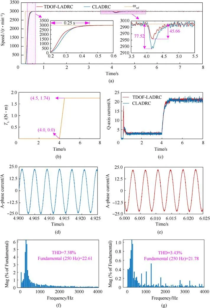
Fig.12.Load experimental results:(a)Speed;(b)Load torque;(c)Q-axis current;(d)Phase-A current of CLADRC;(e)Phase-A current of TDOF-LADRC;(f)FFT results of CLADRC;(g)FFT results of TDOF-LADRC.
Parameter mismatch in the PMSM system is a typical source of uncertain disturbances.Therefore, parameter mismatch experiments are conducted to evaluate the ability of the proposed TDOF-LADRC strategy to suppress uncertain disturbances[30].The inductance value and resistance value of PMSM in the program are adjusted to ±50% deviation from their standard values, and both no-load and load experiments are conducted.The experimental results are shown in Fig.14.From Fig.14, it is evident that the impact of inductance and resistance mismatches on the dynamic performance, steady-state performance, and disturbance rejection performance of the PMSM system is relatively negligible.Moreover,the speed curves with and without motor parameter mismatches are nearly identical.The experimental results indicate that the TDOF-LADRC inherits the advantage of CLADRC in effectively suppressing uncertain disturbances.
4.5.Sinusoidal reference speed tracking experiment results
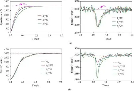
Fig.13.The experimental results of different controller parameters: (a) Changing kp; (b) Changing ωo.

Table 2 Setting times and speed drops with different controller parameters.

Fig.14.Parameter mismatch experimental results.
While tracking the sinusoidal reference speed, the PMSM system is influenced by frictional disturbances that vary with speed.Additionally,the friction torque displays pronounced non-linearity at zero speed points.Therefore, performing the sinusoidal reference speed tracking experiment is an effective method to evaluate the PMSM system's performance in rejecting nonlinear time-varying disturbances, and the accuracy of tracking the sinusoidal reference speed reflects the system's ability to suppress these nonlinear time-varying disturbances.The sinusoidal reference speed is set to 3000 r/min with a frequency of 1 Hz, and the parameters for TDOF-LADRC and CLADRC speed controllers are configured as follows: kp=50, ωo=100, and b0=603.18.The experimental results are presented in Fig.15.
From Fig.15, it is evident that PMSM systems employing different speed controllers can accurately track the sinusoidal reference speed without noticeable phase lag or speed decay.The speed error range for CLADRC is±150 r/min,while the speed error for TDOF-LADRC is only ±60 r/min.Compared to CLADRC, TDOFLADRC exhibits a 60% reduction in the speed error range.Furthermore,TDOF-LADRC demonstrates significantly smaller speed error fluctuations than CLADRC, particularly at peak speeds and zero speed points.The experimental results powerfully demonstrate that TDOF-LADRC significantly outperforms CLADRC in rejecting nonlinear time-varying disturbances.
4.6.Quantitative analysis and comparison between TDOF-LADRC and CLADRC
In order to quantitatively compare the enhancement of antidisturbance performance and TDOF characteristics between TDOF-LADRC and CLADRC, a comprehensive analysis is performed on the experimental outcomes of both controllers.The analysis covered four aspects:maximum speed drop during load mutation,waveform quality of phase currents, sinusoidal reference speed tracking error, and decoupling of dynamic and anti-disturbance performance.Direct comparison of the maximum speed drop under sudden load increase allows for evaluating the anti-load disturbance performance of PMSM systems utilizing TDOF-LADRC and CLADRC, thereby indicating the extent of improvement in suppressing constant and slowly varying disturbances by employing TDOF-LADRC in the PMSM system.Moreover,comparing the waveform quality of phase currents allows for a direct comparison of the steady-state performance between TDOFLADRC and CLADRC, further reflecting the performance and efficiency of the PMSM system in steady-state.Additionally, the sinusoidal reference speed tracking error reflects the ability of the two controllers to suppress nonlinear time-varying disturbances.The average absolute error eAVGand root mean square error eRMSare defined to quantitatively analyze the tracking error of sinusoidal reference speed,

Fig.15.Sinusoidal reference speed tracking experiment results: (a) Speed; (b) Speed error.

Table 3 Quantitative analysis and comparison between TDOF-LADRC and CLADRC.
where,e(i)represents the sinusoidal reference speed tracking error.
The results presented in Table 3 are obtained based on load experiments, sinusoidal tracking experiments, and verification experiments of the characteristics of TDOF.Analysis of Table 3 reveals that the PMSM system utilizing TDOF-LADRC exhibits a reduced speed drop of 31.86 r/min compared to the PMSM system employing CLADRC,indicating a 41.1%improvement in suppressing constant and slowly varying disturbances as achieved by TDOFLADRC.Moreover, the THD of phase-A current in the PMSM system employing TDOF-LADRC is reduced by 4.15%, signifying a 54.74%enhancement in the steady-state performance of the PMSM system with TDOF-LADRC.Additionally,the PMSM system utilizing CLADRC demonstrates eAVGand eRMSvalues of 62.43 r/min and 74.04 r/min, respectively, whereas TDOF-LADRC reduces these values to 24.34 r/min and 27.84 r/min, respectively.The reduction in eAVGand eRMSamounts to 61.01% and 62.40%, respectively,implying that TDOF-LADRC enhances the disturbance suppression capability of the PMSM system for nonlinear time-varying disturbances by 60%.Furthermore, the PMSM system with TDOF-LADRC achieves complete decoupling between dynamic and antidisturbance performance, as ωoand kpindependently tune them.Therefore,the proposed TDOF-LADRC can be considered a genuine TDOF controller.In conclusion, the proposed TDOF-LADRC comprehensively improves the disturbance rejection performance of the PMSM system while achieving a complete decoupling of dynamic performance and disturbance rejection performance.
5.Conclusions
The highlights and contributions of this paper can be summarized as follows:
(1) An improved TDOF-LADRC is proposed to address unsatisfactory disturbance rejection performance and incomplete decoupling between dynamic performance and disturbance rejection performance in the PMSM system with CLADRC speed controller, which achieves a powerfully robust speed control outcome and reduces the difficulty of tuning controller parameters.
(2) A comparison of disturbance observation capability and antidisturbance performance between the TDOF-LADRC and CLADRC strategies is performed with identical controller parameters.The comparison results demonstrate that the proposed TDOF-LADRC strategy exhibits more precise disturbance observation and superior disturbance rejection performance.
(3) The stability and robustness of the proposed TDOF-LADRC strategy are proved through theoretical analysis and experimental research, demonstrating that it can achieve stable convergence and present excellent anti-disturbance performance to deal with complex time-varying nonlinear disturbances in the PMSM system.
Declaration of competing interest
The authors declare that they have no known competing financial interests or personal relationships that could have appeared to influence the work reported in this paper.
- Defence Technology的其它文章
- Explosion resistance performance of reinforced concrete box girder coated with polyurea: Model test and numerical simulation
- An improved initial rotor position estimation method using highfrequency pulsating voltage injection for PMSM
- Target acquisition performance in the presence of JPEG image compression
- Study of relationship between motion of mechanisms in gas operated weapon and its shock absorber
- Data-driven modeling on anisotropic mechanical behavior of brain tissue with internal pressure
- The effect of reactive plasticizer on viscoelastic and mechanical properties of solid rocket propellants based on different types of HTPB resin

