
A NEW METHOD FOR NUMERICAL SIMULATION OF TWO TRAINS PASSING BY EACH OTHER AT THE SAME SPEED*
2010-05-06 08:22:25ZHAOXiaoli
水動(dòng)力學(xué)研究與進(jìn)展 B輯 2010年5期
ZHAO Xiao-li
School of Aerospace, Tsinghua University, Beijing, China, E-mail: zhao-xl@mails.tsinghua.edu.cn
SUN Zhen-xu
State Key Laboratory for Turbulence and Complex Systems, College of Engineering, Peking University, Beijing, China
A NEW METHOD FOR NUMERICAL SIMULATION OF TWO TRAINS PASSING BY EACH OTHER AT THE SAME SPEED*
ZHAO Xiao-li
School of Aerospace, Tsinghua University, Beijing, China, E-mail: zhao-xl@mails.tsinghua.edu.cn
SUN Zhen-xu
State Key Laboratory for Turbulence and Complex Systems, College of Engineering, Peking University, Beijing, China
(Received February 26, 2010, Revised May 6, 2010)
A new method is proposed to numerically simulate problems of trains passing by each other at the same speed, and is implemented in UDF language of commercial software Fluent. Because only a half of the computational domain is required and the dynamic mesh technique is avoided, the computational efficiency is greatly improved. A two-dimensional test case is used for validation, which shows that the flow field and the pressure wave during the train-passing events can be correctly calculated by this new method. This method can be easily extended to three-dimensional simulations, to deal with practical problems.
trains passing by each other, rotational symmetry, dynamic mesh, pressure wave
1. Introduction
Aerodynamic loads in train-passing problems are becoming more and more important due to the booming development of high speed railways and their effects on the surrounding buildings. Among them the most serious and typical cases are that trains pass by each other at the same speed in a tunnel. Recent investigations mainly focus on real vehicle tests, scaled model experiments and numerical simulations. A series of real vehicle tests were carried out by Takizaw (2 000), Li[1]and Yang[2], during which the basic aerodynamic loads, pressure waves and train winds were measured. Compared to real vehicle tests, numerical simulations require shorter investigation period and lower cost, and most of all, have better ability to simulate extreme conditions which would not occur often in everyday life.
In terms of the computational efficiency, the numerical simulation approaches can be classified into three kinds. The first kind concerns simplified approaches, used for a rapid estimation by solving simplified governing equations or by using engineering empirical formulas, as done by Wang[3]to calculate the pressure pulse on high-speed trains passing by each other. The pressure waves generated by high-speed trains passing by each other in a tunnel were studied by Mei[4,5]with a one dimensional unsteady compressible non-homentropic flow theory. Train-passing problems were simulated by Hermanns[6]through solving the Laplace equation governing the potential flow with the boundary element method. Solutions can be obtained rapidly with this kind of methods, but they are always used in a qualitative instead of quantitative nature as an engineering estimation.
The second kind of methods is to solve the whole computational domain, in which the dynamic mesh technique is also used[7-13]. The dynamic mesh technique was used by Tian[10], Bi[11], Clarke[12]and Liu[13]to study train-passing problems by solving the whole computational domain. Commercial software Fluent was used by Clarke in his study. Results fromLiu reveal no big difference between a compressible flow computation and an incompressible flow computation, and the results from an incompressible flow computation are even much closer to those of real vehicle tests. Quantitative results from a complicated flow field are usually obtained by this kind of methods, but they always require a very large computational domain, the real time grid updating and a sophisticated computer hardware.
A rotational symmetric point can be found in the above train-passing problems, and with this point being set as the pole point, the flow field of the whole domain is periodic in the circumferential direction, with the period of π. Calculations can be performed in one period only, which means that one can consider only a half of the domain in train-passing problems.

The third kind of methods still suffers from slightly low efficiency due to the use of the dynamic mesh technique, especially when the skewness of the grid is sufficiently big. In the present work, a new method is proposed to improve the computational efficiency in simulating trains passing by each other at the same speed. With this method, the dynamic mesh technique is avoided, while only a half of the computational domain is considered, so a better performance can be achieved. For a good applicability, this method is implemented in UDF language by a secondary development of the commercial software Fluent. In order to save computational time but not to lose the generality of this method, a two-dimensional train is considered in this article. Results from two-dimensional test cases show that reasonable pressure waves and flow fields are obtained, which indicate the high efficiency and accuracy of this method.
2. Governing equations
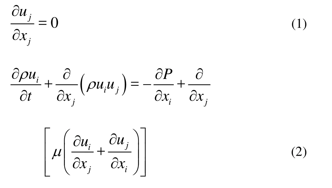
The computational model under consideration is a two-dimensional incompressible flow. The primary transport variables are the flow velocity uiand the pressureP. They are governed by the conservation equations of mass and momentum:
3. Numerical algorithms
For incompressible Navier-Stokes equations, a SIMPLEC algorithm is adopted in the present work, with an implicit scheme for temporal discretization.
3.1 Boundary conditions
A basic rotational symmetry exists in the problem of trains passing by each other at the same speed, with the rotational symmetric Point O at the middle of the trains and with the period of π. As shown in Fig.1, with origin of the inertial coordinate system at Point O, Point A and Point A' are the corresponding points and the flow variables and coordinates of Point A and Point A' will satisfy the following relationships:
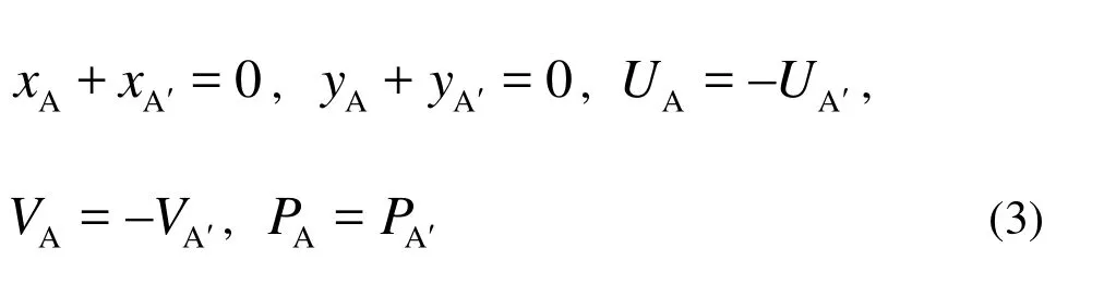
where x, y , U , V ,P are x coordinate, y coordinate, the velocity in x direction, the velocity in y direction and the pressure, respectively.

Fig.1 Schematic diagram of trains passing by each other used in literature[14-16]
Based on the above relationships, a new boundary condition can be specified to consider only a half of the computational domain. A ghost grid line outside the center line is used in the half-domain simulation. Flow variables on the ghost grid line can be deduced from the variables on the interior grid line based on Eq.(3). Studies were carried out in thisdirection in literature[14-16], but the efficiency remains not satisfactory due to the use of dynamic mesh technique.
In order to avoid the use of dynamic mesh technique and further improve the computational efficiency, a new boundary condition is proposed here. Rather than using the inertial coordinate system, a moving coordinate system fixed on the train is used such that the rotational symmetric Point O is moving towards the train in the opposite direction, as shown in Fig.2.
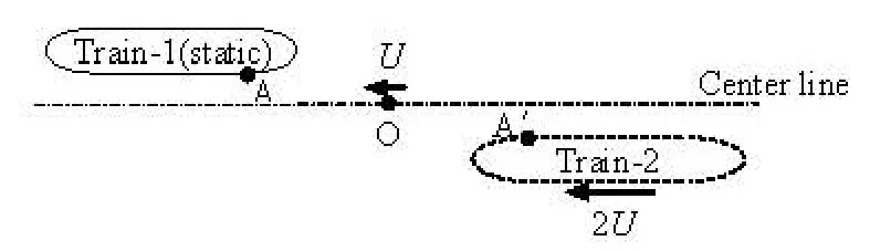
Fig.2 Schematic diagram of trains passing by each other in the approach of this article
Based on the moving coordinate system, the relationships of flow variables and coordinates between Point A and its corresponding Point A' are as follows:
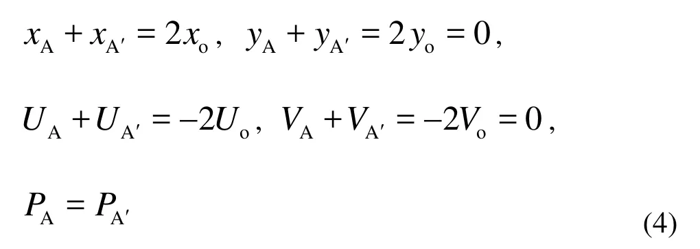
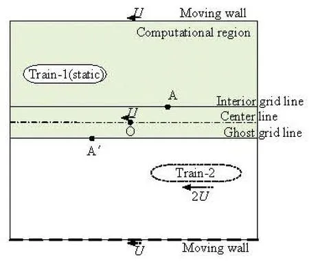
Fig.3 Computational domain and the rotational symmetric boundary
As shown in Fig.3, the shaded area is the computational domain, which is just a half of the whole domain. In the new coordinate system, the upper boundary is a moving wall, and the three lines at the bottom of the domain are the ghost grid line, the center line and the interior grid line, respectively. Variables at the ghost grid line and the interior grid line exchange data at the beginning of every iteration. The rotational symmetric Point O lies on the center line and moves at the train’s speed in the opposite direction. In order to simplify the task of the settings in the inlet and outlet boundaries of the domain, a periodic condition is used, because for incompressible viscous flow, the influence of the trail vortexes can be neglected as long as the computational domain is long enough.
3.2 Solution procedure
For the secondary development of commercial software Fluent, a schematic diagram of the procedures is shown in Fig.4. The shaded area is implemented in UDF, while the non-shaded area is completed by Fluent itself. At the beginning of each iteration, the velocity distributions are extracted from the interior grid line and sent to corresponding points on the ghost grid line according to the relationships in Eq.(4). After that a new temporal iteration can be continued with this new velocity inlet boundary condition.
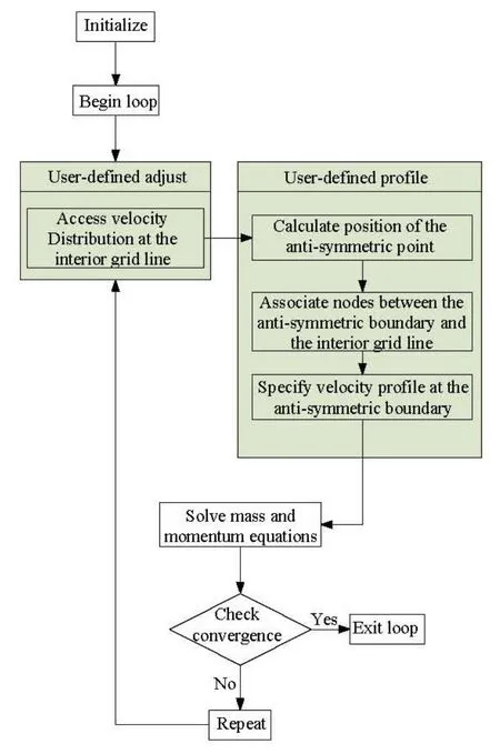
Fig.4 Schematic diagram of solution procedure
4. Numerical results
A simulation of trains passing by each other at the same speed of 10 m/s is carried out. The model used in this case is 25 m long and 3m wide, and the vertical distance between the center lines of the trains is 4 m. As shown in Fig.5 and Fig.6, a structural meshis used with a total number of meshes of 1.04×10⁶. The mesh around the train has refined to achieve a better numerical result.

Fig.5 The whole grid
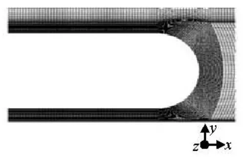
Fig.6 Grid around the train
The characteristic time during the trains passing by each other is shown in Fig.7.
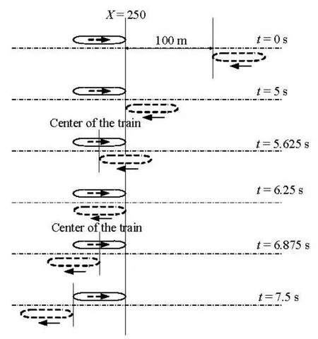
Fig.7 Schematic diagram of trains passing by each other
A transformation of coordinate systems is made for post-processing to return to the traditional observation ways, and the other half of the computational domain is filled with its flow variables obtained by Eq.(4). With the origin of the inertial coordinate system fixed on the rotational symmetric Point O, streamlines at different places at t=4s are plotted. Streamlines around the train in the computational domain are shown in Fig.8. Figure 9 shows the streamlines between the two trains. Streamlines around the rotational symmetric Point O are shown in Fig.10. As seen in these figures, streamlines are well connected when crossing the center line. The vortex around the rotational point and the trail vortexes are all well captured by this method. The former is a typical feature during the trains passing by each other as a result of the strong velocity shear layer around the rotational point, while the latter is a typical result of flow around a bluff body. Above results indicate that this new method performs well in the train-passing problems and typical flow features can be captured by this method.
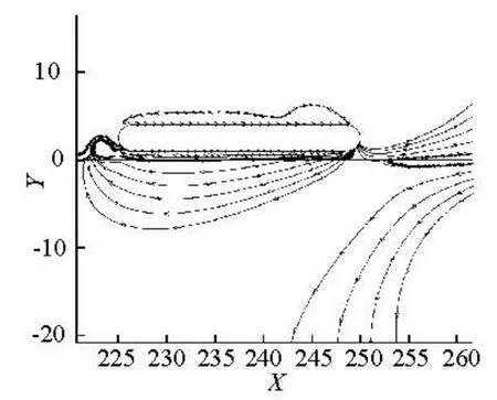
Fig.8 Streamlines around the train at t=4s
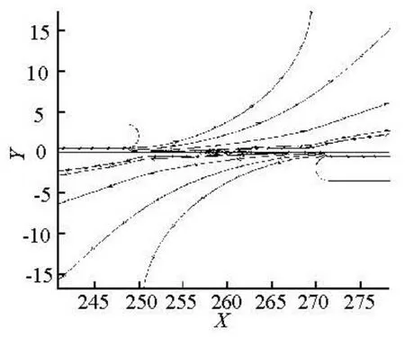
Fig.9 Streamlines between the two trains at t=4s
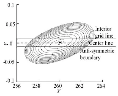
Fig.10 Streamlines around the rotational point at t=4s
Another remarkable feature during trains passing by each other is the pressure wave. Four pressure monitoring points are fixed on the side of the train, as shown in Fig.11. Time histories of pressure at these points are given in Figs.12-15. The train out of the computational domain is approaching these points from t=5.1s, then a positive pressure wave appears at these points successively due to the compression of air. When the trail of the train passes by these points, a negative pressure wave appears as a result of the opening area. The pressure nearly keeps a constant value before the positive pressure wave and after the negative pressure wave, which means that thedisturbance from the train outside the computational domain is very little when they are at a long distance. These are the basic features for pressure wave in train-passing problems, as demonstrated in Figs. 12-15.
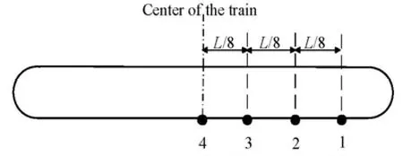
Fig.11 Locations of pressure monitoring points

Fig.12 Time history of pressure at Point 1
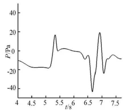
Fig.13 Time history of pressure at Point 2
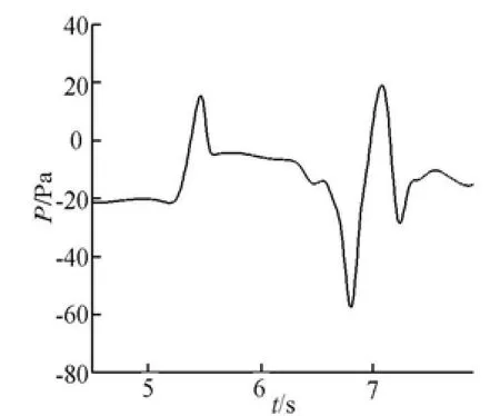
Fig.14 Time history of pressure at Point 3
In order to study the influence of the train-passing process on the surrounding buildings, a pressure probe is placed in front of the train in the inertial coordinate system, as shown in Fig.16. And a single-train case is also shown there. Figure 17 shows the time history of the pressure variation on the pressure probe. If only one train passes by this probe, the pressure keeps constant before the train arrives and after the train leaves. A pressure wave appears when the head of the train or the trail of the train passes by this probe. The increase of the positive pressure is restrained by a negative pressure zone on the shoulder of the train, so that the positive peak of the pressure waves is always a little smaller than the negative part. On the other hand, if trains pass by each other, a higher positive peak of the pressure waves appears due to the much stronger compression of air, while the negative part nearly keeps the same as in the former case. Because of the interaction of the trail vortexes from the two trains, oscillations occur at the pressure probe. It can be deduced from the above analysis that a worse damage to the surrounding buildings will be caused by trains passing by each other than a single-train, which can be correctly described by the method proposed in this article.
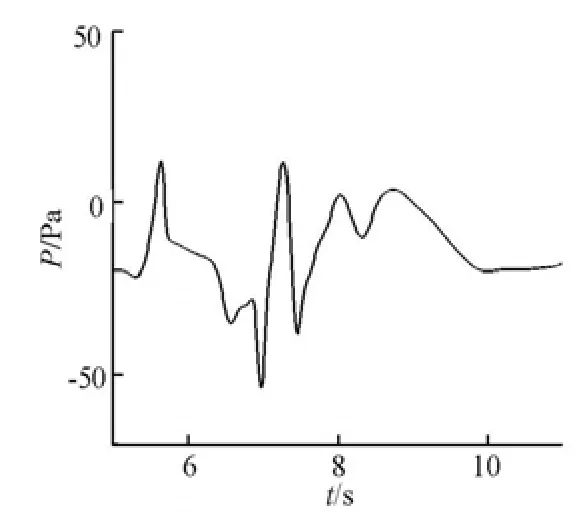
Fig.15 Time history of pressure at Point 4
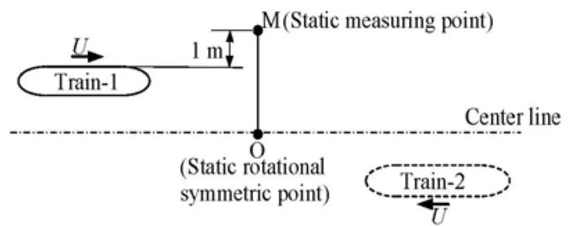
Fig.16 Schematic diagram of the pressure probe in front of the train
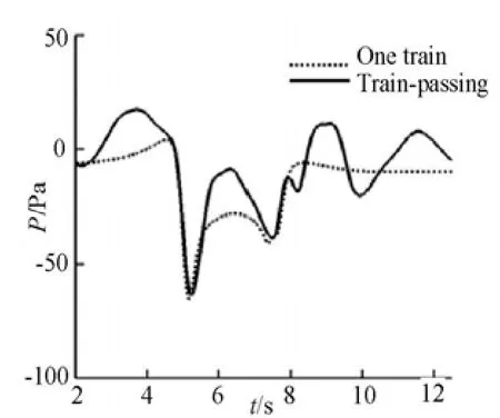
Fig.17 Time history of pressure variation on the pressure probe
5. Conclusions
For the solution of train-passing problems, thehuge amount of computational cost and inevitable dynamic mesh technique are always the most important issue for traditional approaches, and the latter would greatly lower the computational efficiency. Based on the basic features of train-passing problems, a new method is proposed to solve these problems. Using the rotational symmetric boundary condition, the flow variables on the ghost grid line can be obtained from the interior grid line through specific relationships. Only a half of the computational domain needs to be solved and the dynamic mesh technique can be avoided by this method at the same time. The key procedure in this method is the transformation of the coordinate system. Besides, the periodic conditions used in the inlet and outlet boundaries of the computational domain greatly improve the independency from the initial flow field, which avoids the incorrect use of the rotational symmetric boundary condition for a steady initial flow field in literature[14-16]. Theoretically speaking, an accurate flow field will be achieved after several computational periods. To insure the applicability, the UDF language coupled with Fluent is used for this method. The basic function of UDF is to exchange data between an interior grid line and a rotational symmetric boundary before each iteration and the solution of train-passing problems shows a great benefit of this method. With small computational cost, basic flow features can all be captured by this method without the use of dynamic mesh technique.
Cases of two-dimensional incompressible flow are studied in the present work, and the feasibility to use this method to simulate train-passing problems is verified. An extension to three-dimensional problems of this method can be expected, which means that this method can be easily used to solve real train-passing problems.
Acknowledgements
The authors would like to thank Professor Chen Yao-song and An Yi-ran for their great support and precious advice for this article.
[1] LI Ming-shui, LEI Bo and LIN Guo-bin et al. Field measurement of passing pressure and train induced airflow speed on high speed maglev vehicles[J]. Acta Aerodynamica Sinica, 2006, 24(2): 209-212(in Chinese).
[2] YANG Ming-zhi, YUAN Xian-xu and XIONG Xiao-hui et al. Experiment study of pressure pulse caused by trains passing each other on Guangzhou-Shenzhen railway for the sixth speed-up[J]. Journal of Experiments in Fluid Mechanics, 2008, 22(2): 56-60(in Chinese).
[3] WANG Xun-cun. Study on pressure pulses on highspeed trains passing each other[J]. Railway Locomotive and CAR, 2000, (4): 1-4(in Chinese).
[4] MEI Yuan-gui, YU Nan-yang. Boundary conditions for train crossing pressure waves in a tunnel[J]. Journal of Lanzhou Railway Institute, 1999, 18(1): 61-65(in Chinese).
[5] MEI Yuan-gui, YU Nan-yang and ZHAO Hai-heng et al. Numerical method on transient pressure with high speed trains crossing through a tunnel[J]. Journal of the China Railway Society, 2002, 24(2): 21-25(in Chinese).
[6] HERMANNS L., GIMéNEZ J. G. and ALARCóN E. Efficient computation of the pressures developed during high-speed train passing events[J]. Computers and Structures, 2005, 83(10-11): 793-803.
[7] LI Li, DU Guang-sheng and LIU Zheng-gang et al. The transient aerodynamic characteristics around vans running into a road tunnel[J]. Journal of Hydrodynamics, 2010, 22(2): 283-288.
[8] HUANG Yuan-dong, GAO Wei and KIM Chang-Nyung. A numerical study of the train-induced unsteady airflow in a subway tunnel with natural ventilation ducts using the dynamic layering method[J]. Journal of Hydrodynamics, 2010, 22(2): 164-172.
[9] JIANG Bo, TIAN Mao-cheng and LENG Xue-li et al. Numerical simulation of flow and heat transfer characteristics outside a periodically vibrating tube[J]. Journal of Hydrodynamics, 2008, 20(5): 629-636.
[10] TIAN Hong-qi, HE De-xin. 3-D numerical calculation of the air pressure pulse from two trains passing by each other[J]. Journal of the China Railway Society, 2001, 23(3): 18-22(in Chinese).
[11] BI Hai-quan, LEI Bo and ZHANG Wei-hua. Numerical study of the pressure load caused by high-speed passing maglev trains[J]. Acta Aerodynamica Sinica, 2006, 24(2): 213-217(in Chinese).
[12] CLARKE J., FILIPPONE A. Unsteady computational analysis of vehicle passing[J]. Journal of Fluids Engineering, 2007, 129(3): 359-367.
[13] LIU Jie, LI Ren-xian and ZHAO Jing. Simulation analysis of aerodynamic force for high speed trains passing at the same speed[J]. Rolling Stock, 2009, 47(3): 5-9(in Chinese).
[14] HWANG J., LEE D. Numerical simulation of flowfield around high speed trains passing by each other[C]. AIAA 17th Applied Aerodynamics Conference. Norfolk, VA, USA, 1999, AIAA-1999-3156.
[15] HWANG J., YOON T. and LEE D. et al. Numerical study of unsteady flowfield around high speed trains passing by each other[J]. JSME International Journal Series B-Fluids and Thermal Engineering, 2001, 44(3): 451-464.
[16] KOZO F., TAKANOBU O. Aerodynamics of high speed trains passing by each other[J]. Computers and Fluids, 1995, 24(8): 897-908.
10.1016/S1001-6058(09)60105-0
* Biography: ZHAO Xiao-li (1983-), Male, Ph. D.
SUN Zhen-xu, E-mail: sunzhenxu@gmail.com
 水動(dòng)力學(xué)研究與進(jìn)展 B輯2010年5期
- 水動(dòng)力學(xué)研究與進(jìn)展 B輯的其它文章
- NUMERICAL SIMULATION OF THE ENERGY DISSIPATION CHARACTERISTICS IN STILLING BASIN OF MULTI-HORIZONTAL SUBMERGED JETS*
- ANALYSIS OF EDL EFFECTS ON THE FLOW AND FLOW STABILITY IN MICROCHANNELS*
- EXPERIMENTAL INVESTIGATION ON THE DRAG REDUCTION CHARACTERISTICS OF TRAVELING WAVY WALL AT HIGH REYNOLDS NUMBER IN WIND TUNNEL*
- NUMERICAL MODELING PURIFICATION PERFORMANCE OF POT TEST*
- NUMERICAL STUDY OF CAVITATION ON THE SURFACE OF THE GUIDE VANE IN THREE GORGES HYDROPOWER UNIT*
- THE COMPARATIVE STUDY OF VENTILATED SUPER CAVITY SHAPE IN WATER TUNNEL AND INFINITE FLOW FIELD*