
EXPERIMENTAL INVESTIGATION ON THE DRAG REDUCTION CHARACTERISTICS OF TRAVELING WAVY WALL AT HIGH REYNOLDS NUMBER IN WIND TUNNEL*
2010-05-06 08:22:31YAOYan
水動(dòng)力學(xué)研究與進(jìn)展 B輯 2010年5期
YAO Yan
Department of Engineering Mechanics, Shanghai Jiao Tong University, Shanghai 200240, China
Beijing Electromechanic Engineering Institute, Beijing 100074, China, E-mail: yaoyanyy@163.com
LU Chuan-jing
Department of Engineering Mechanics, Shanghai Jiao Tong University, Shanghai 200240, China
State Key Laboratory of Ocean Engineering, Shanghai Jiao Tong University, Shanghai 200030, China
SI Ting
Department of Modern Mechanics, University of Science and Technology of China, Hefei 230027, China
ZHU Kun
Beijing Electromechanic Engineering Institute, Beijing 100074, China
EXPERIMENTAL INVESTIGATION ON THE DRAG REDUCTION CHARACTERISTICS OF TRAVELING WAVY WALL AT HIGH REYNOLDS NUMBER IN WIND TUNNEL*
YAO Yan
Department of Engineering Mechanics, Shanghai Jiao Tong University, Shanghai 200240, China
Beijing Electromechanic Engineering Institute, Beijing 100074, China, E-mail: yaoyanyy@163.com
LU Chuan-jing
Department of Engineering Mechanics, Shanghai Jiao Tong University, Shanghai 200240, China
State Key Laboratory of Ocean Engineering, Shanghai Jiao Tong University, Shanghai 200030, China
SI Ting
Department of Modern Mechanics, University of Science and Technology of China, Hefei 230027, China
ZHU Kun
Beijing Electromechanic Engineering Institute, Beijing 100074, China
(Received March 29, 2010, Revised July 10, 2010)
Drag reduction experiments of the traveling wavy wall at high Reynolds number, ranging from 1.46×10⁶to 5.83×10⁶based on the free-stream velocity and the model length, were conducted. A suit of traveling wavy wall device was developed and its characteristics of drag reduction at high Reynolds number were investigated. The drag forces of the traveling wavy wall with various wave speeds (c) were measured at different wind speeds (U) in the FL-8 low-speed wind tunnel and compared with the drag force of the flat plate. The results show that the mean drag force of the traveling wavy wall decreases as the value of c/ U increases, at different wind velocities, the values of c/ U corresponding to minimal drag force of the traveling wavy wall are different, when the values of c/ U are larger than 0.6, the mean drag forces of the traveling wavy wall are smaller than those of the flat plate, and the drag reduction can be up to 60%. The drag reduction effectiveness of traveling wavy wall is thus achieved. Furthermore, as the value of c/ U increases, the traveling wavy wall can restrain the separation and improve the quality of flow field.
flow control, drag reduction, traveling wavy wall, wind tunnel test
1. Introduction
Minimizing the surface friction of aircraft and ships is a long-term goal in engineering design. Generally, the surface friction accounts for as large as 50% of the total resultant drag. For submarines, the ratio can be up to 70%. In recent years, the research of drag reduction becomes more and more attractive.
Conventional methods for the drag reduction make use of the low-resistance streamline shape and decrease surface protruding structures as far as possible. The examples can be taken for the car of the streamline body and the submarine of water droplet shape and so on. However, these methods are all passive and the effect of its drag-reducing has been proved limited. Contrarily, more and more active flow control technologies for drag reduction have been developed, one of which is based on the traveling wavy wall. In this method, a smooth wavy wall undergoes the motion in the form of a streamwise traveling wave and is found to exhibit restraining turbulence intensity and separation as the phase speed of the traveling wave is increased to reach somevalues comparable to the free stream velocity. Reynolds number by using the large eddy simulation.
It must be pointed out that most of previous experiments were conducted at low Reynolds number. In the present work, we perform experimental investigation of the traveling wavy wall at h6igh Reynold6s number, which ranges from 1.46×10 to 5.83×10 based on the free-stream velocity U and the experimental model length L. The drag forces of the traveling wavy wall, flat plate and fixed wavy wall are also measured in the wind tunnel. The article is organized as follows. In Section 2 the experimental method is described. The experimental device to generating traveling wavy wall with high phase speed is developed and is placed in the wind tunnel to measure the drag force. In Section 3 the experimental results and related discussions are presented. Finally the main conclusions are drawn in Section 4.
2. Experimental apparatus and method
The motion equation of the traveling wavy wall is described in the following
where A is the reciprocating movement distance of the pole, f the frequency and Φ the phase of the gas cylinder. In this way, if a number of gas cylinders with the same frequency are placed equidistantly and two neighboring ones have an equal phase difference ΔΦ , the vertices of the poles will move along an approximate sine curve. Note that the shape of this curve is mainly determined by the frequency and the responsive time of the gas cylinders.
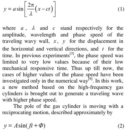
Following this consideration, we developed an experimental device as shown in Fig.1, consisting of aflexible plate, seven knightheads, seven air cylinders, seven electromagnetic valves, a control circuit, some fixed supports and a number of windpipes. The seven air cylinders (ISO standard, with compressed air as working medium) with A=100 mm were placed in the fixed support at the same interval l =300 mm. A flexible plate with width of 300 mm was connected to the poles of seven air cylinders by seven metal knightheads. Seven electromagnetic valves controlled by a control circuit system were fixed on the support and connected one by one with the gas cylinders by a number of windpipes. When the gas cylinder was working, air was compressed into one gate and extruded from the other gate of the gas cylinder. Either in or out was decided by the signals of the electromagnetic valve. When the valve was opened, the pole was moving upwards, while when the valve was closed, the pole was moving downwards. The control circuit system could set the frequencies and switches of seven electromagnetic valves. The phase difference ΔΦ of two neighboring gas cylinder was settled to be π/2, and then the flexible plate was moving approximately in the form of Eq.(1). Note that the forehead and the tail of the flexible plate were located in the center line of the whole wave, the forehead is fixed on the support while the tail is free.
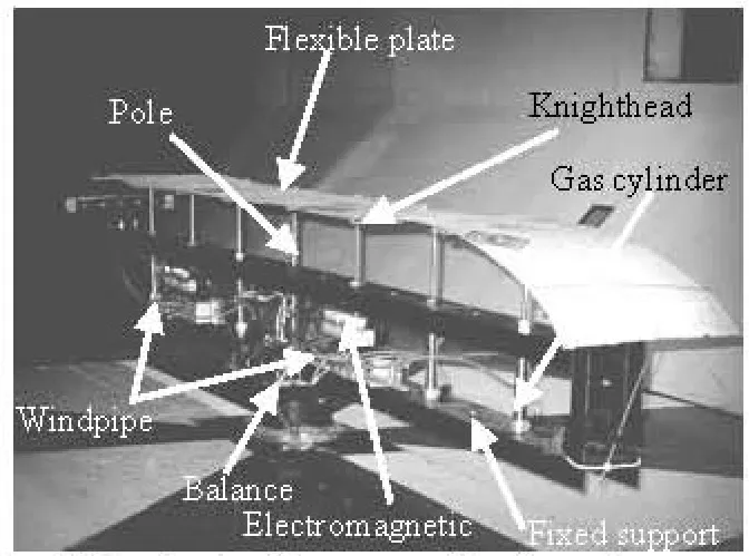
Fig.1 The device for generating traveling wavy wall
The experiment was conducted in the FL-8 low-speed wind tunnel, which is a single flat circular wind tunnel with the maximum speed up to 72 m/s and the average turbulence degree 0.1745%. The size of the test section is 3.5 m×2.5 m×5.5 m. The experimental device was supported by an 8BM03-01 semi-mode balance in the test section (see Fig.1). Although the balance was designed to measure six components of the load, the drag force in the horizontal direction was especially concerned in order to obtain the drag of the traveling wavy wall.
In the experiment, how to measure the drag of the flexible plate separately is a difficult problem. In order to prevent the influence of the resistance of the device, the device was vertically placed on the balance, and a set of oriented equipment consisting of boards and organic glasses was fixed in the wind tunnel as shown in Fig.2. The front of the oriented equipment was designed to be triangle shape, the upper surface of which was plane with the same height as the forehead of the flexible plate. Note that the oriented equipment surrounding the experimental device was not linked with it but has a little spacing. Then the measured force in the streamwise direction is mainly the drag force of the flexible plate.
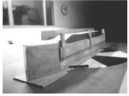
Fig.2 The photo of experimental models in the wind tunnel
The experimental data were collected by a VXI data acquisition system. Collecting a data point cost 0.02 s. Then in each case we spent more than 6 s to collect 300 data points for analysis.
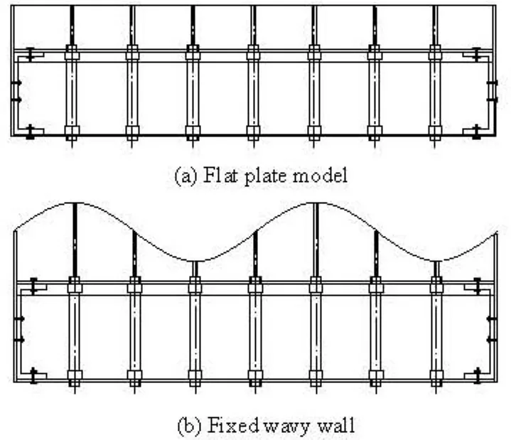
Fig.3 Configuration of experimental models
3. Results and discussions
In the experiment, the drag force of the traveling wavy wall as well as the flat plate and the fixed wavy walls (i.e., c=0) under five oscillation frequencies were measured. Figure 3 show the shape of the two fixed model, Flat plate model is flat, that is, the height of the air cylinders are its 1/2 of its maximum stroke, the same level as the fixed support. Fixed wavy wall model takes on the fixed wavy shape, similar to sinusoidal wave. The first air cylinder is at the highest point of its stroke.
3.1 Drag force of the flat plate and fixed wavy wall
To identify flow is turbulent or laminar flow, the key parameter is the Reynolds number. The critical
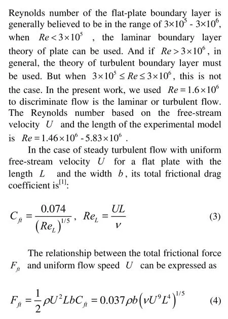
Figure 4 shows the drag forces for of flat plate and fixed wavy wall at different free-stream speeds. From the figure, it can be seen that with the increase of the free-stream speed, the drag force increases by the square of the speed.
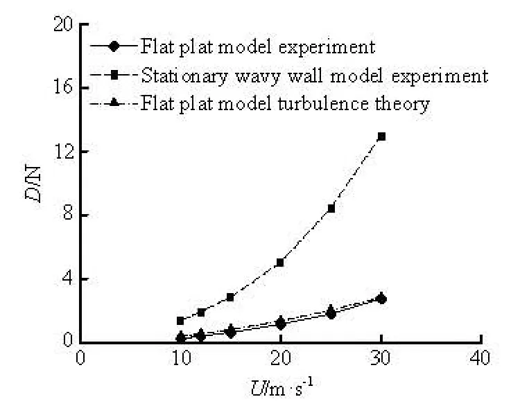
Fig.4 Drag forces for flat plate and fixed wavy wall versus the free-stream speed
The drag force for the flat plate is significantly smaller than that for the fixed wavy wall. The fixed wavy wall not only bears the frictional resistance, but also endures the pressure drag, and behind of the crest of fixed wavy wall there is apparent flow separation. Meanwhile, the experimental data for drag force of flat plate are in good agreement with the theoretical values from turbulent boundary.
3.2 Drag force of the traveling wavy wall at different wave velocities
The ratio of the traveling wave speed, c, to the free-stream speed, U, c/ U , is an important parameter, and different values of c/ U correspond to the different characteristics of the flow field. In unsteady flow, the Strouhal number St, is generally introduced to describe the feature of the unsteady flow field. For the two-dimensional traveling wavy wall problem, the Strouhal number is characterized by the length of the wavelengthλ:
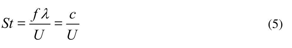
which implies the Strouhal number determines the character of the flow field.
In the present work, the amplitude of the traveling wave is constant. By adjusting the oscillation frequency of air cylinder to change the phase speed of the traveling wavy wall. Under different oscillation frequenciesf=2 Hz, 3 Hz, 4 Hz, 5 Hz, 6 Hz, the corresponding phase speeds are c = λf =2.4 m/s, 3.6 m/s, 4.8 m/s, 6 m/s, 7.2 m/s. Table 1 gaves a list of c/ U corresponding to different frequencies and free-stream velocities.flow pattern and dynamics depend strongly on the phase speed c. as c increases, the friction force increases, the pressure force decreases monotonically, and the total drag force decreases. The present measurement results are in good agreement with their computational conclusion.
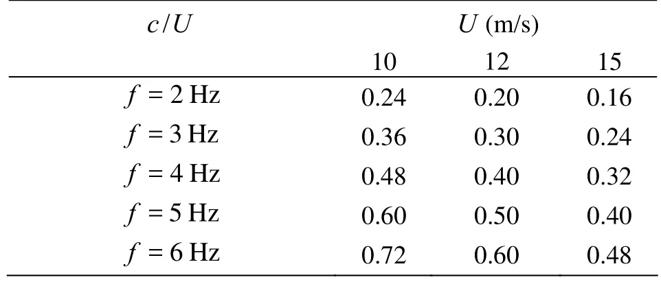
Table 1 c/ U forer different frequencies and free-stream velocities
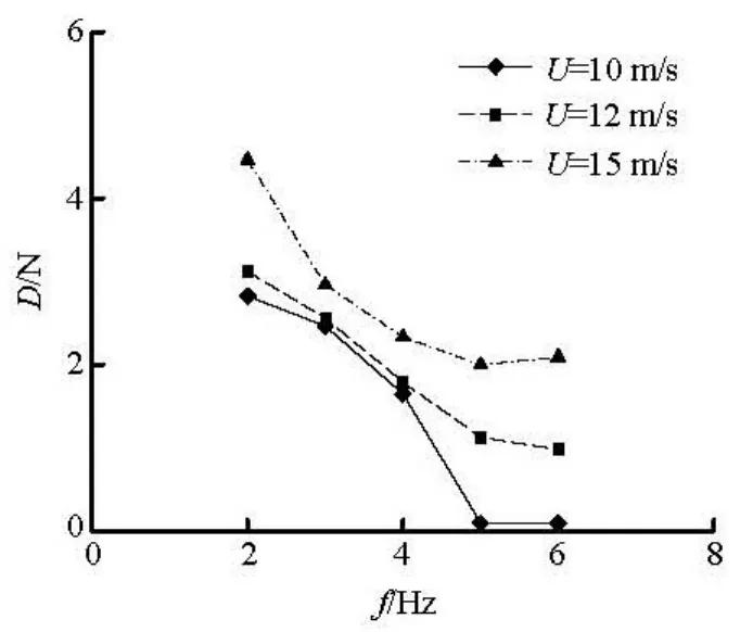
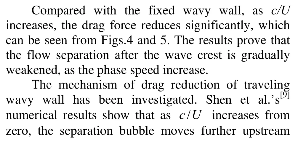
Fig.5 The curve of drag force of traveling wavy wall versus frequency
3.3 Comparison of flat plate of drag force for fixed wavy wall and traveling-wavy wall
Figure 5 shows that the drag force of traveling wavy wall reaches its minimum, at the free stream velocity U=10m/s and the oscillation frequency f=6 Hz. Table 2 gives the comparison of drag forces for the flat plate, the fixed and traveling wavy plate. It can be seen that traveling wave indeed plays a crucial role in reducing the drag force. For the ratio U , c/ U ≥ 0.6 ( U=10 m/s ), the drag force reduction is about 60%.

Table 2 Drag forces for flat plate,fixedand traveling wavy walls (Unit: N)
4. Conclusions
A suit of smooth flexible traveling wavy wall devices have been designed and experimentally examined for turbulent flows over the wall undergoing streamwise traveling-wave and transverse motions. The Reynolds number based on the free-stream velocity U and the experimental length L is O(106), and the traveling wave amplitude a is given by2 πa/λ=0.26.
By changing the ratio of the traveling wave phase speed c to the free-stream velocity U, it is found that the wall oscillations can be optimized to achieve separation suppression and turbulence reduction, and to reduce drag force.
At the same free-stream velocity U,with incresing oscillation frequency, the wavy wall drag force decreases. That is to say, as c/ U increases, the drag force for traveling wavy wall is generally reduced. At different free-stream velocity, when the traveling wavy wall gives minimal drag force, the corresponding values of c/ U are also different.
Compared with the flat plate, experimental results show that the traveling wavy wall indeed plays the role of drag reduction, as c/ U ≥0.6. And the drag reduction is about 60 %.
With c/ U ingrom zero, experimental studies show that the traveling wavy wall has the mechanisms of separation elimination and turbulence reduction.
[1] SCHLICHTING H., GERSTEN K. and KRAUSE E. et al. Boundary-layer theory[M]. 8th Edition, New York: Springer, 2000.
[2] KENDALL J. M. The turbulent boundary layer over a wall with progressive surface waves[J]. Journal of Fluid Mechanics, 1970, 41: 259-281.
[3] TANEDA S., TOMONARI Y. An experiment on the flow around a waving plate[J]. Journal of the Physical Society of Japan, 1974, 36: 1683-1689.
[4] TANEDA S. Visual study of unsteady separated flows around bodies[J]. Prog. Aerosp. Sci., 1977, 85: 287-348.
[5] SAVCHENKO Y. N. Hydrodynamic effects of a traveling wave[R]. Kyiv, Ukraine: USSR Bionics Trans., JPRS L/ 9420, 1980.
[6] WU Jian-ming, WU Chui-jie and WU Jie-zhi et al. Preliminary study of nonlinear flow over traveling wavy wall[C]. International Symposium on Nonsteady Fluid Dynamics. Toronto, Canada, 1990, 359-368.
[7] WU Jie-zhi, WU Jian-ming. Vorticity dynamics on boundaries[J]. Advances in Applied Mechanics, 1996, 32: 119-275.
[8] TECHET A. H. Experimental visualization of the near-boundary hydrodynamics about fish-like swimming motion[D]. Ph. D. Thesis, Cambridge, MA, USA: MIT, 2000.
[9] SHEN Lian, ZHANG Xiang and YUE D. K. P. et al. Turbulent flow over a flexible wall undergoing a streamwise traveling wave motion[J]. Journal of Fluid Mechanics, 2003, 484: 197-221.
[10] LU Xi-yun, YIN Xie-zhen. Propulsive performance of fish-like traveling wavy wall[J]. Acta Mechanica, 2005, 175: 197-215.
[11] WU Chui-jie, XIE Yan-qiong and WU Jie-zhi. “Fluid roller bearing” effect and flow control[J]. Acta Mechanica, sinica 2003, 19(5): 476-484.
[12] DONG Gen-jin, LU Xi-yun. Numerical analysis on the propulsive performance and vortex shedding of fish-like traveling wavy plate[J]. Int. J. Num. Methods Fluids, 2005, 48(12): 1351-1373.
[13] YANG Zhu, WU Jie-zhi. Drag reduction by axisymmetric traveling wavy wall[J]. Journal of University of Science and Technology of China, 2005, 35(4): 471-479.
[14] TRIANTAFYLLOU M. S., TECHET A. H. et al. Vorticity control in fish-like propulsion and maneuvering[J]. Integr. Comp. Biol., 2002, 42: 1026-1031.
[15] ZHANG Zhi-xin, LUO Zhen-ou. Numerical calculation of three-dimensional boundary layers over moving wavy wall[J]. Journal of Hydrodynamics, Ser. A, 2000, 15(3): 287-292(in Chinese).
[16] CAI Shu-peng, JIN Guo-yu and LI Da-mei et al. Drag reduction effect of coupling flexible tubes with turbulent flow[J]. Journal of Hydrodynamics, 2008, 20(1): 96-100.
[17] ZOU Lin, LIN Yu-feng. Numerical simulation of turbulent flow around wavy cylinders at a subcritical Reynolds number and the investigation on drag reduction[J]. Chinese Journal of Hydrodynamics, 2010, 26(1): 31-36(in Chinese).
10.1016/S1001-6058(09)60108-6
* Biography: YAO Yan (1978-), Female, Ph. D. Candidate, Engineer
 水動(dòng)力學(xué)研究與進(jìn)展 B輯2010年5期
- 水動(dòng)力學(xué)研究與進(jìn)展 B輯的其它文章
- NUMERICAL SIMULATION OF THE ENERGY DISSIPATION CHARACTERISTICS IN STILLING BASIN OF MULTI-HORIZONTAL SUBMERGED JETS*
- ANALYSIS OF EDL EFFECTS ON THE FLOW AND FLOW STABILITY IN MICROCHANNELS*
- NUMERICAL MODELING PURIFICATION PERFORMANCE OF POT TEST*
- NUMERICAL STUDY OF CAVITATION ON THE SURFACE OF THE GUIDE VANE IN THREE GORGES HYDROPOWER UNIT*
- A NEW METHOD FOR NUMERICAL SIMULATION OF TWO TRAINS PASSING BY EACH OTHER AT THE SAME SPEED*
- THE COMPARATIVE STUDY OF VENTILATED SUPER CAVITY SHAPE IN WATER TUNNEL AND INFINITE FLOW FIELD*