
Design of Non-contact On-load Automatic Regulating Voltage Transformer
2015-12-29 01:22:38ZhaoQi
Zhao Qi
Substation Maintenance Room, State Grid Harbin Power Supply Company, Harbin 150036, China
Design of Non-contact On-load Automatic Regulating Voltage Transformer
Zhao Qi
Substation Maintenance Room, State Grid Harbin Power Supply Company, Harbin 150036, China
At present, an automatic-mechanic contact tap-changer is widely used in power system, but it can not frequently operate. In addition, arc will occur when the switch changes. In order to solve these two problems, this paper presented an automatic on-load voltage-regulating distributing transformer which employed non-contact solid-state relay as tap-changer, and mainly introduced its structure, basic principal, design method of each key link and experimental results. Laboratory simulation experiments informed that the scheme was feasible. It was a smooth and effective experiment device, which was practical in application.
solid-state relay, on-load tap-changer, non-contact, distributing transformer design
Introduction
Automatic on-load voltage regulation of a transformer is an effective measure to stabilize power network voltage. At present, an automatic-mechanic contact tap-changer is widely used in power systems, but it cannot sustain operation. In addition, arc will occur when the switch changes, so it must be installed in an independent oil tank. Cooke (1992) solved the problem of arc occurring when the switch changed by using an on-load, voltage-regulating, tap-changer in which the thyristor acts as its auxiliary switch (Zhang, 2009; Li et al., 2006). But this device also had mechanical part and could not operate consistently, so drawbacks still remained. Zhu et al. (2002) connected the primary side of the auxiliary transformer with the main transformer and used the thyristor to change the secondary tap joint of the auxiliary transformer to regulating voltage (Wang et al., 2006; Zhao and Song, 2013; Li et al., 2012; Zhao et al., 2010; Zhang et al., 2010). This method could operate quickly, but arc did not occur. But this method required a complex auxiliary transformer and large-capacity thyristor, adding to the cost of the transformer and limiting the switch's application field. Therefore, it is not fit for a distributing transformer, due to its cost and performance (Huang and Li, 2011; Ning et al., 2010).
The power electronic component can be easily controlled and switched quickly. In addition, arc will not occur in the process of switching. If used as an on-load tap-changer of the transformer, the switch would have a low cost and long lifetime and could be regulated frequently. This paper introduced an automatic on-load voltage-regulating distributing transformer which employed non-contact solidstate relay as tap-changer, and mainly introduced its structure, basic principal, design method of each key link and experimental result.
Main Circuit and Operation Process of Transformer
Main circuit of transformer
The device was comprised of a transformer, noncontact tap-changer, circular current-limiting circuit,and a control unit. Its wiring diagram is shown in Fig. 1.
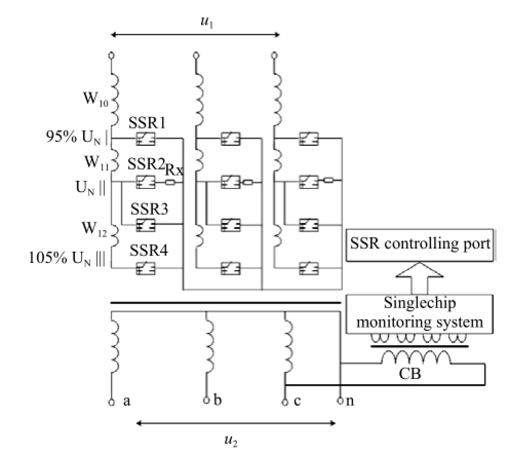
Fig. 1 Wiring diagram of main circuit
Automatic voltage-regulating process of transformer
The storage battery supplied power for the monitor-ing system before the distributing transformer was powered to put SSR3 in "ON" state. When the transformer was switched on, the output voltage of the transformer was automatically detected by a single-chip monitoring system. If the voltages exceeded the permitted range of fluctuation, the automatic on-load voltage-regulating program would be operated. As shown in Fig. 2, the current-limiting resistance Rx was connected to the tap joint switching circuit first, and then was switched to the tap joint. This could limit the value of the circular current.
The whole layout of transformer
Solid-state relay as a non-contact tap-changer, arc would not occur when it changed, so it could use the same oil tank with transformer winding. The sample used a S9-50 kVA-10/0.4 kV, energy-saving distributing transformer with a conservator. For the convenientce of commissioning, the sample had changed the conservator a bit, that was, put the noncontact tap-changer which made up of solid-state relay and the controller which made up of AT89C52 (AT89C52 was a low-voltage, high-performance CMOS 8-bit microcontroller) into the conservator. Primary winding tap joint and phase voltage of secondary side were introduced into the conservator by the oil passage to link with SSR and CB. Thus, not only reduced the transformer volume, but also resolved the question about electronic components which might out of control in cold winter. The specific install diagram is shown in Fig. 3.

Fig. 2 Flow chart of automatic on-load voltage regulation
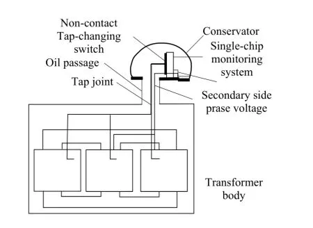
Fig. 3 Structure picture of automatic on-load voltage distributing transformer
Choose of Non-contact Tap-changer Parameter
Choose of solid-state relay
When chose solid-state relay, we should mainly consider the factors of endure voltage, current and the question that current should match with transformer overcorrect protection. According to these, the sample transformer adopted 40 A/660 V AC solid-state relay as tap-changer.
Choice of current-limiting resistance
By literature (Zhao and Dong, 2010) analysis, we could know the reactance of this loop was very light. The circumfluence was determined by the electromotive force and current-limiting resistance in series with the loop. The current-limiting resistance of the sample transformer was 10 Ω, and the power was 20 W. This choice completely met the demand of safety, reliable and smooth transition was proven by laboratory and running in locale.
Design of computer monitoring unit
According to the design idea of safe, reliable, the precision of automatic steady voltage was good, the response was fast, and the system was steady, economy, and applicable, the sample transformer adopted AT89C52 as the core of the controller, C language programming, and three-phrase trigger the monitoring unit, respectively.
Choice of current-limiting resistance
When the distributing transformer primary side occurred single-phase ground fault, non-grounded phrase voltage raised the line voltage. From Fig. 1, we could see if the insulation resistance between SSR direct and AC loop was very high, under the voltage SSR easy breakdown. The sample adopted the method of adding 0.01 μF condenser between AC loop side of the solid-state relay and the secondary sides of the CB to protect the solid-state relay and control circuit. The experiment proved that this method to use was feasible.
Experimental and Circulating Result
In order to further verify the sample of automatic onload regulating voltage transformer based on noncontact solid-state relay working performance's stability and dependability, we had carried on the simulation experiment in the laboratory for the sample transformer, run it in locale and examined .
Simulation experiment content and purpose in laboratory
To validate the ability of the bearing voltage for the solid-state relay and movement dependability, we had carried imitate experiment in the laboratory. On the basis that it was operated in sound conditionally, we could do the automatic steady voltage function experiment of the non-contact on-load automatically regulating voltage device.
Experiment connection
In the laboratory, connected the regulator whose outputting voltage was 0-450 V with the step-up transformer gotting the necessary voltage of AC source simulation power network 0-11000V. Emploied the resistance box and the motor as the load of experiment transformer. The simulation experiment connection in the laboratory is shown in Fig. 4.
In Fig. 4, Ttwas regulator, T1was a step-up transformer, T2was sample, M was 7.5 kW electromotor, R was 5 kW resistance box, K1and K2were load switches, V1was the output voltage of regulator to calculate the high voltage of sample, V2was the output line voltage of the sample, and SC was DS5202CA style digital oscillograph.
Examination experiment ability of bearing voltage of solid-state relay
Through regulating the regulator to make the primary voltage of sample V2=8 056-11 582 V, make SSR1 and SSR4 turn on separately, the switch whichendured the highest voltage SSRmax, the calculated the highest voltage Umax, and endure time T are shown in Table 1.
From Table 1, we could know under the unloaded state, no matter which tap-changer was on, it was normal for the device to work, SSR could not be damaged, it indicated that the ability of the bearing voltage of 660 V solid state relay could meet the demand of the peak voltage during the switch changing for non-contact on-load automatically regulating voltage distributing transformer.
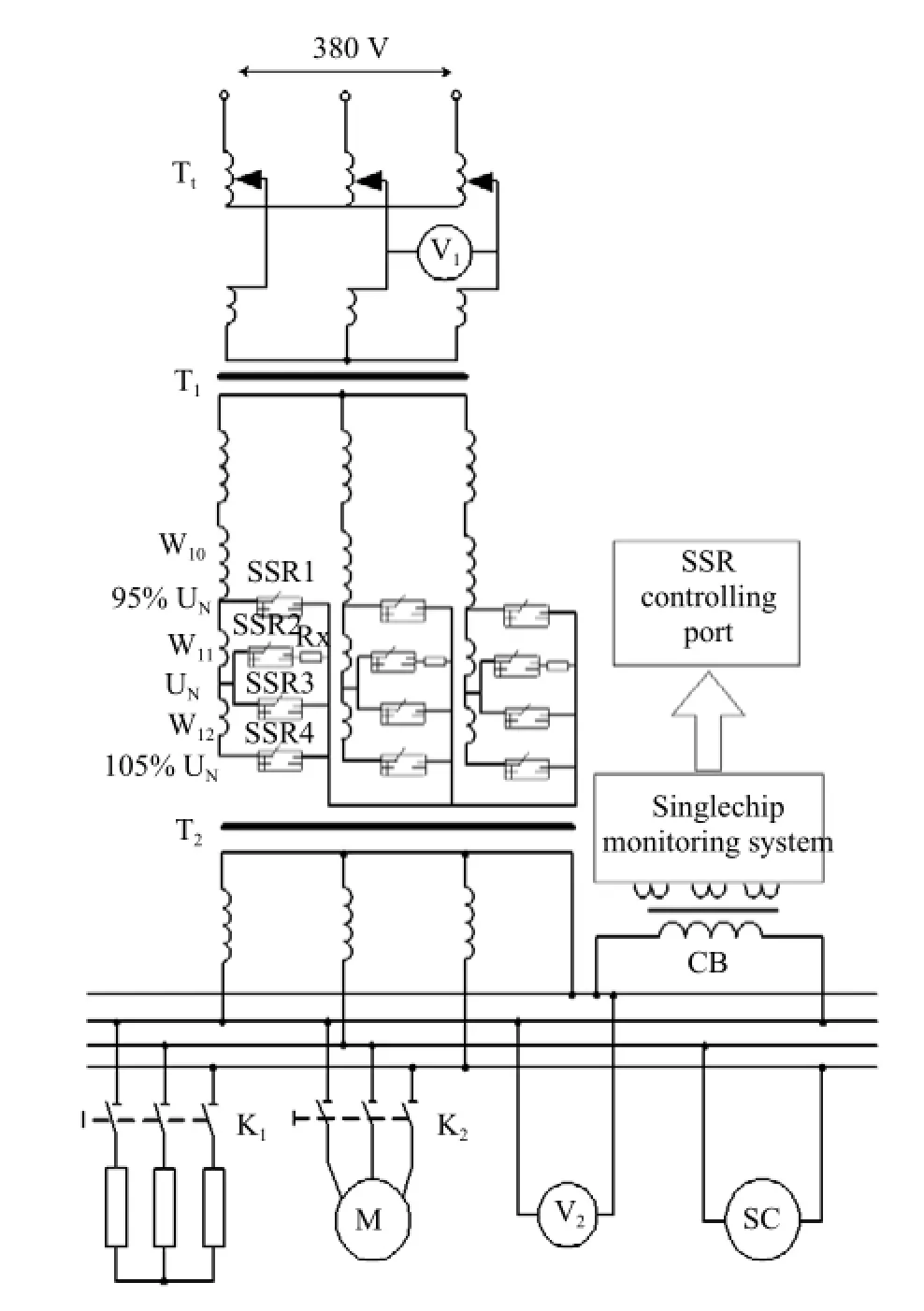
Fig. 4 Wiring diagram of simulating experiment

Table 1 Endured the highest voltage SSRmax, calculated the highest voltage Umax, and endured time T of switch
Circumfluence experiment
During the experiment, changed primary side voltage of the sample many times, made it regulate in 9-11 kV repeatedly, SSR changed repeatedly, it was reliable to operate and did not occur overcurrent, SSR damage phenomenon, it was proved that adopt 20 Ω currentlimiting resistance could limit the current in allowable scope, the dependability of SSR met the requirement of the transformer.
Start-up experiment of non-contact on-load automatically regulating voltage device
When turned on the switch, power was transmited to primary side, because there was no voltage at the secondary side, and the control circuit had no power, so all the SSR would be off, SSR broken down because of the bearing voltage of the power network. This project adopted the battery to start, that was to say the battery supplied power for the control unit before running, making SSR3 be on. When primary side turned on the switch, SSR3 made three phases neutral link together, made secondary side output the voltage, then the control circuit was supplied power by the power transformer, the device entered the state of on-load automatically regulating voltage.
Turned on the switch repeatedly in the laboratory to transmit power for the transformer, SSR could not be damaged. After turning on the switch, we regulated the input voltage, the sample entered the state of onload automatically regulating voltage, which proved that this kind of method was feasible.
Experiment of automatic steady voltage function
Regulating Ttunder the load state, output voltage of sample changing with the input voltage, by regulating voltage seven times, when output voltage Ttchanged between 355 V and 445 V, the sample corresponding output voltage. Changing curve is shown in Fig. 5.
From Fig. 5, we could easily find when the output voltage of regulator changed from 360 V to 440 V,output voltage of the sample changed from 378 V to 412 V. It proved that the automatic had steady voltage function.

Fig. 5 Comparision photo of automatic steady voltage function
Detection of harmonic aberrance
In the experiment of automatic steady vltage function, the output waveform had been recorded by DS5202CA type digital oscillo graph, as shown in Fig. 6. It showed that the non-contact on-load automatically regulating voltage distributing transformer did not produce harmonic aberrance.

Fig. 6 Output voltage waveform of sample
Withstanding voltage test for sample
Between primary winding and secondary winding with tap-changer applied 30 000 V AC voltage, for one minute, the tap-changer and windings were not damaged. It proved that the protective measure of SSR and control unit was feasible.
Result of running in locale
The experiment sample began running at 16 o'clock on October 15, 2014 in Heilongjiang Province of China. So far, it had been operating safety. The power consumer voltage recorded by computer which before and after the sample run is shown in Fig. 7

Fig. 7 Comparision photo of automatic steady voltage function
Fig. 7 indicated that the voltage quality had been improved after the sample operation. If in the area of large fluctuating range of the voltage, the result would be more obvious.
Conclusions
Theory analysis, experimental and running results indicated that adopting the solid-state relay as the on-load tap-changer of distributing transformer was feasible. The waveform distortion was small, and it could effectively stabilize output voltage. If took suitable protection method, it woud meet the demand of safe, steady and reliable operation. The characteristics of this sample were quick operation, non-arc, frequent operatior, small volume, long lifetime and low cost.
Cooke G H. 1992. New thyristor-assisted diverter switch for on-load transformer tap changers. IEE Proceedings,139(6): 507-511.
Huang J J, Li X M. 2011. Contactor-less OLTC system based ondynamic model. Electric Power Automation Equipment,31(8): 52-57.
Li X M, Wang W Q, Zhang S C, et al. 2006. An arcless OLTC model based on arm-bridge structure. Automation of Electric Power Systems,30(7): 55-59.
Li M C, Su T, Wu J H, et al. 2012. Based on the research of transformer on-load tap-changer. Transformer,49(2): 59-60.
Ning Z H, Luo L F, Zhang J, et al. 2010. Design of optical fiber trigger system for thyristor in medium-high voltage static reactive power compensation. Electric Power Automation Equipment,30(6): 31-34.
Wang J L, Li J Y, Xu L Y, et al. 2006. Scheme of arcless on-load voltage regulation for distribution transformer using high power electronic switch. Automation of Electric Power Systems,30(15): 97-102.
Zhao Y L, Dong S T. 2006. Study on non contact automatic on-load voltage regulating distributing transformer based on solid state relay, Conference Proceedings IPEMC2006 306EX1405 Vol1. pp. 484-488.
Zhao Y L, Dong S T, Liang Q Y. 2010. Research and implementation of non-contact on-load automatic regulate voltage distribution transformer based on solid-state relay. Electrical Engineering,8: 178-181.
Zhao Y L, Song W. 2013. Optical trigger scheme of inverse-parallel thyristor in contactless on-load tap-changing voltage for distribution transformer. Automation of Electric Power Systems,37(20): 97-101.
Zhu G R. Li M Z, Liu X D, et al. 2002. Voltage regulation method in series thyristor of distribution transformer. Transformer,22(5): 1001-8425.
Zhang P X. 2009. Study on on-load automatic tap-changer based on thyristor. Northeast Agriculture University, Harbin.
Zhang W, Zhang Z J, Song X Y, et al. 2010. Development of new onload tap changer. Transformer,47(9): 34-36.
TM4
A
1006-8104(2015)-03-0091-06
Received 11 June 2015
Zhao Qi (1988-), male, assistant engineer, engaged in the research of high voltage testing technology. E-mail: zyl5631@163.com
 Journal of Northeast Agricultural University(English Edition)2015年3期
- Journal of Northeast Agricultural University(English Edition)的其它文章
- Chinese Comprehensive Rural Reform: Institutional Vicissitude, Theoretic Framework and Content Structure
- Acceptability of Bush Meat as a Source of Animal Protein in Delta State, Nigeria: Implication for Extension Services
- Preparation of Mouse Embryonic Stem Cells and Cardiomyocyte Differentiation Induced with Retinoic Acid and Ascorbic Acid
- Contents of Trace Metal Elements in Cow Milk Impacted by Different Feedstuffs
- Predatory Efficacy of Cotton Inhabiting Spiders on Bemisiatabaci, Amrascadevastans Thripstabaci and Helicoverpa armigera in Laboratory Conditions
- Effect of Bacillus subtilis and Pseudomonas fluorescens on Growth of Greenhouse Tomato and Rhizosphere Microbial Community