
Shortcut Method of Design and Energy-Saving Analysis of Sargent Dividing Wall Column
2019-01-18 02:51:18FangJingChengXiaominLiXiaochunXiangNingLiChunli
中國煉油與石油化工 2018年4期
Fang Jing; Cheng Xiaomin; Li Xiaochun; Xiang Ning; Li Chunli
(School of Chemical Engineering, Hebei University of Technology, Tianjin 300130)
Abstract: The Sargent dividing wall column can implement four products separation sequences in one column based on Fully Thermally Coupled Distillation Column. The initial design parameters are required for the design optimization or dynamic control of the Sargent dividing wall column, and in order to make the rigorous simulation of the Sargent dividing wall column more conducive to convergence, a ten column model for complex Sargent column is established in this paper, and the shortcut design method of this model is proposed. The internal minimum vapor and liquid f low are obtained by the Underwood equations and the mass balance method and the V-min method. The separation for a 4-component shortcut mixture of pentane, hexane, heptane and octane was considered, while the initial values of design parameters and the ratio of vapor-liquid distribution of each column were calculated by using the shortcut design method of a ten column model. And by comparing the shortcut calculations with rigorous simulation results, the practicality and reliability of shortcut calculations were verified. The reason for energy saving was analyzed based on back-mixing. A virtual heat exchanger is proposed to make the Sargent dividing wall column more energy efficient.
Key words: Sargent dividing wall column; shortcut design method; energy saving; virtual heat exchangers
1 Introduction
Distillation is the most commonly used separation operation in the chemical process, and its energy consumption accounts for about 60% of the total energy consumption of the chemical equipment, so it is very essential to save the energy of distillation separation process in order to reduce the total energy consumption of the chemical equipment[1]. Therefore on the premise of the separation requirements, reducing the energy input or the consumption of energy is the primary task of the distillation process. Currently, the main energy saving technology in distillation process can be divided into the following two categories: (1) the improvement of the distillation column equipment, such as the use of highly efficient structured packing in place of the column stage or inefficient packing, etc.; (2) the unit process coupling, such as the dividing wall column (DWC), the multi-effect distillation[2], the heat pump distillation[3], the reactive distillation, the thermally coupled distillation[3-4], etc.
Actually DWC[5]is a completely heat coupled distillation column equipped with a condenser and a reboiler, and it can achieve multi-product separation task in one shell which usually needs conventional multi-column distillation sequences. It has the advantages of avoiding the back-mixing, reducing energy consumption, and decreasing the equipment investment cost[6]. In recent years, as a typical equipment capable of reducing the energy consumption of distillation system, DWC has received wide attention. So far, only the single-partition wall DWCs have found wide application in practice[7]. However, by adopting the non-welded partition wall technology[8-9], it becomes possible not only to expand the application window for three products columns, but also to think of implementing four and more products separation in one DWC. Two feasible options for the four-product dividing wall columns mainly include the Kaibel dividing wall column[10]and the Sargent dividing wall column[11]. The Kaibel column has two side-draws with one partition wall and longitudinal sections in offcentre position. The Sargent column (Figure 1) has three partition walls and is divided into three sections in parallel, it saves energy by 17.4% compared to the Kaibel column and by 50% compared to the conventional distillation sequences[12]. Sargent column is a more attractive option for industrial implementation.

Figure 1 Schematic illustration of Sargent dividing wall column
At present, the research of the Sargent column is mainly based on the V-min diagram[13]and the Petlyuk column[14]. This paper upon analyzing the structure of the Sargent column and considering the effect of vapor and liquid split ratios on the vapor and liquid f low rate in the whole column, proposes a relatively viable shortcut calculation method of ten column model in order to separate the mixture of four components.
2 Ten Column Model
2.1 Structural analysis
Fully thermally coupled Petlyuk column (Figure 2) for separating a four-component mixture consists of two prefractionators and a main-column, while a prefractionator delivers two products as the feed streams to the three-product middle-column for feeding the maincolumn, which acts as a product column[15]. The Sargent column (Figure 1) includes three vapor and liquid split ratios, respectively. Two prefractionators are installed in the main-column in conf iguration and three longitudinal partitions are structurally set up into the column which is divided into three sections connected in parallel. The feed in the prefractionator is a mixture of four components A, B, C and D, where A is the lightest component and D is the heaviest component based on their boiling points. The prefractionator performs a sharp split between A and D f irstly, while allowing intermediate components to be distributed in both streams. The streams of ABC and BCD from the two ends of the prefractionator enter the middle-column, where the streams ABC are separated in the upper portion while the streams BCD are separated in the lower portion. Finally, the more difficult binary splits are performed in the main-column, and then the products A and D are collected at the top and the bottom of the Sargent column, respectively, while the products B and C are gathered, respectively, in the side section at their maximum concentration. Thus the mass transfer and heat transfer of multi-streams between the three columns are realized in one column shell.
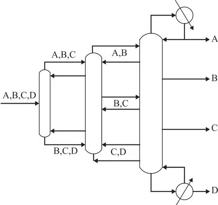
Figure 2 Fully thermally coupled Petlyuk column for separation of a four-component mixture
2.2 Ten column model
In the shortcut calculation of the Sargent column for separating the four-component mixture (A, B, C, and D), the ten column model (Figure 3) is regarded as an equivalent to the Fully Thermally Coupled Distillation Column (FTCD). The ten column model is divided into four parts:
Prefractionator is a shortcut non-sharp splitting column to perform the easy separation of the light key component A and heavy key component D.
PartⅠ includes column C21, C22, C31, and C32. C21 and C22 are the rectifying section and the stripping section, respectively, to achieve non-sharp A/C split. Similarly, C31 and C32 can perform a more difficult sharp A /B split.
PartⅡ includes column C23, C24, C34, and C35. C23 and C24 are the rectifying section and the stripping section, respectively, to achieve non-sharp B/D split. Similarly, C34 and C35 can perform a more difficult sharp C/D split.
C33 performs a more difficult sharp B/C split.
The method proposed by Carlberg and Westerberg[16-17]is applied to simplify the design freedom of the system, and the difference of vapor and liquid f low connecting two columns is assumed to the net product f low rate that is a fixed value which is determined by internal mass balance of each column. This shortcut method is based on assumptions of constant molar flows and constant relative volatilities, therefore it holds for (near) ideal mixtures.
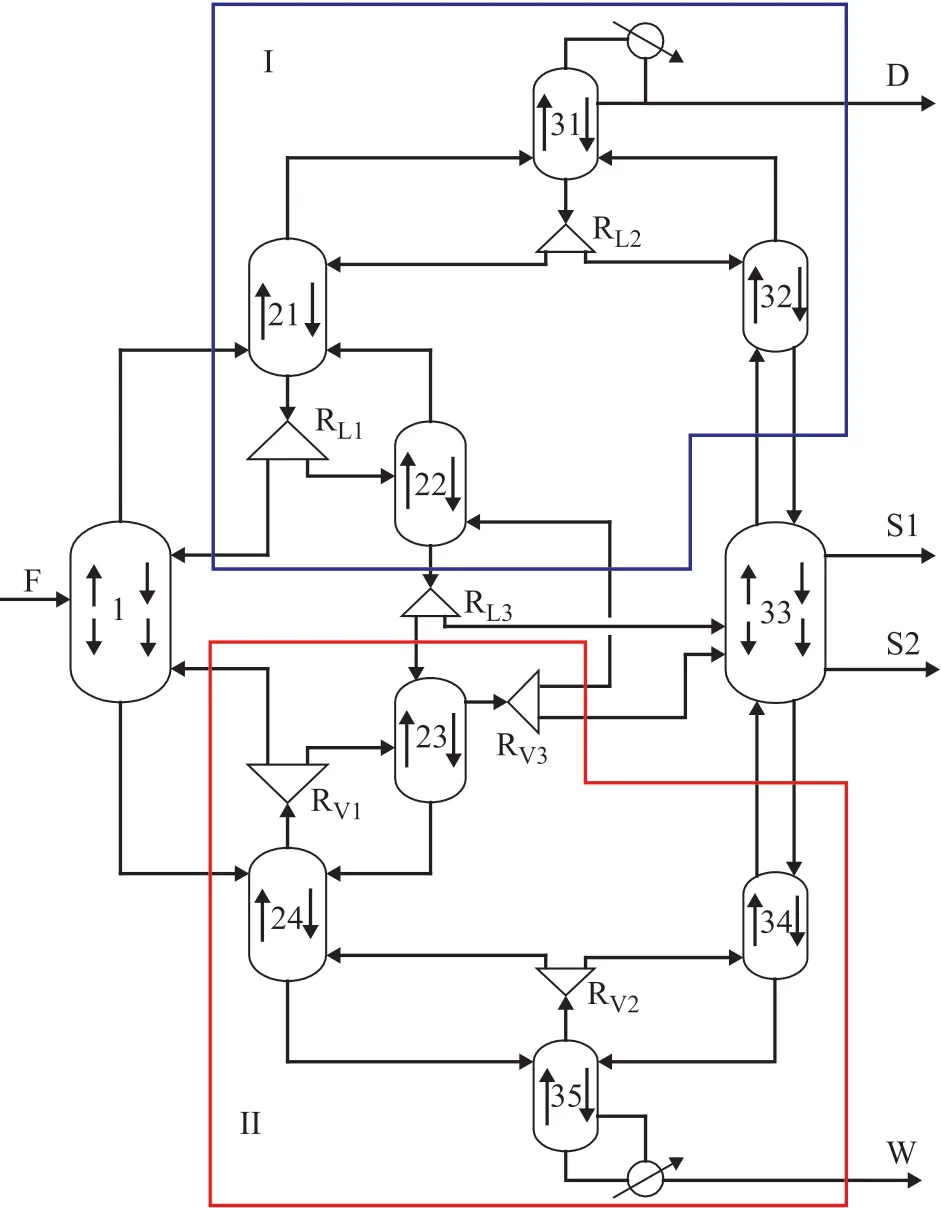
Figure 3 Ten column model for Sargent column obtained by the shortcut design
3 Shortcut Design Method
3.1 Mass balance
By analyzing the Sargent column, the quantitative relationship between the feed and the product can be calculated by the following equations.

By writing the total and component mass balances for the whole column to get the minimum allowable flows inside each section, there will be 8 equations (component balances) and 20 unknowns, which means that 12 variables should be specified in order to solve the mass balance equations. This paper assumes that the composition of the component in two sections is away related with each other. For example, the composition of the lightest component in side stream 2 and bottom stream is nearly zero. According to the quality of the products required by the industry, we set the compositions of D, B, S1, and S2.
3.2 Distributing components and product recoveries
Our task is to f ind the product recoveries (or component flows) and the vapor flow by given a series of feasible specifications. The key of this solution is to identify the distributing components. A component in the feed is distributing ifit appears in all products or is exactly at the limit of becoming distributed if the vapor f low is reduced with an inf initesimal amount. The computation procedure is as follows:
Suppose there areNddistributing components, denoted as {d1,d3, …,dNd-1,dNd}. The recoveries in the top areri,T=1 for all non-distributing light components (i<N1) andri,T=0 for the non-distributing heavy components (i>Nd). The recoveries of the non-distributing componentsNC-Ndare obtained by giving split set, whileNCis the total number of components in a column.
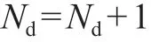
The common Underwood roots of equation (4) will be those values in the range of the volatility of the nondistributing components (αd1-1>θk>αdNd-1) when a given column is operated according to the preferred split. This implies that, withNddistributing components, the number of common roots is:
The minimum vapor f low in equation (5) for a given set of component splits ( or ) is obtained by substituting the common roots of equation (4).
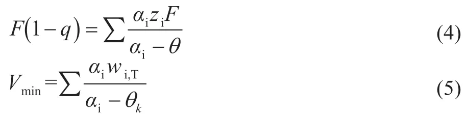
wherewiis defined as the net product flow rate of componenti. For example, in column C1, the difference between V1and L1is equal to the net product f low rateD1at the top of the column.
There areNaequations by substituting different rootsθkinto equation (5), the unknown quantities can be solved from the linear equation set in the following equation:

To specify the product split, we introduce the following extra equation:

ForV>Vminand an inf inite number of stages, there are no common Underwood roots. Thus, at most one component may be distributing and its recovery is independent of the actual value ofV, it is uniquely related toDthrough the equation (8).

3.3 Preferred split
The characteristic of the preferred split is that the heaviest component is removed from the top and the lightest component is removed from the bottom, which is the minimum-energy solution.
For the prefractionator C1 operating at the preferred split, with the four feed components A, B, C, and D, there are three common roots (θA,θB, andθC) that will be active in other related columns respectively. The peaks and nodes corresponding to the solid lines in Figure 4 are in the pre-fractionation operation of all columns, and the minimum energy consumption of the column depends on the separation between the binary components, which corresponds to the highest peak. The minimum vapor f low and liquid f low can be obtained by the following V-min diagram[13](Figure 4).
3.4 Minimum energy of Sargent column
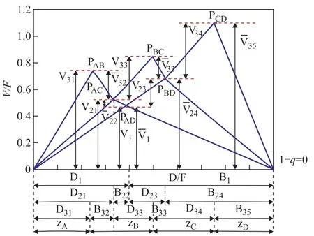
Figure 4 V-min diagram for a given four-component feed (note that the subscript min should be on every vapor f low)
The minimum vapor flow in each column section is calculated by the Underwood equations. Constant molar f low rate and constant relative volatility are assumed for the equations, so the relative volatility (αA,αB,αC,αD) and feed quality (q) are needed.
It can be known that all of the possible common roots from the feed equation depend only on feed composition and quality and not on how the column is operated[13]. The method for calculating the minimum vapor flow of each column section has been explained in Section 3.2. Theqof other columns except column C1 can be calculated from vapor-liquid phase f low rate of the feed. For example, the q value of column C21 can be obtained by equation (9).
The minimum total vapor flow requirement is the same as the required vapor flow for the most difficult split between two of the specified products if that separation is to be carried out in a single conventional two-product column. So the minimum total vapor f low of the Sargent column can be expressed by the following equation:
whereVis the vapor f low rate of the rectifying section, kmol/h.is the vapor f low rate of the stripping section, kmol/h.
3.5 Split ratios
Upon considering the vapor and liquid splits in the ten model, vapor and liquid flow in each column can change easily within the limits of mass balance, and the quality requirements of the products can be achieved, meanwhile, the minimum energy consumption relatively can be reached by optimizing the split ratios of liquid. The split ratios of liquid and vaporRL1,RL2,RL3,RV1,RV2andRV3can be calculated by the minimum liquid f low or the minimum vapor f low. For example, the equations for calculatingRL1andRV1are as follows:
where the split between componentsiandjis expressed asi/j.
It is observed that vapor and liquid split ratios are calculated according to the feed composition and quality in a single column with an inf inite number of stages.
3.6 Practical operation
We may operate some of the columns away from the preferred splits in practical operation, and change operation in some parts of the Sargent column without affecting the maximal of minimum vapor flow[13]. The actual ref lux ratioRin practical operation is assumed to be the following equation:

wherekneeds to be calculated. Column C21 and column C23 are combined to calculate the minimum theoretical number of stages as a distillation column, and column C31 and column C32, column C23 and column C24, and column C34 and column C35 are also combined during the calculation, respectively.
The total annual cost increases as the number of stages and the ref lux ratio increase, but the increase in the ref lux ratio will result in a decrease in the number of stages, soN(R+1) is used to measure the total annual cost. The number of stages in each column is calculated by the Underwood-Fenske-Gilliland-Kirkbride correlation equation, and the feed position is calculated by Kirkbride[18]. The minimum value ofN(R+1) corresponds to the optimalkvalue. Through the above calculation, we can get all the design parameters of the Sargent column through the shortcut design method.
4 Case Study
4.1 V-min method
In this study, this paper considered the separation for an equimolar 4-component mixture of alkanes (40 kmol/h, A: pentane, B: hexane, C: heptane and D: octane,q=1) with a relative volatility of 14: 6.4: 2.4: 1. Table 1 contains the relevant data for characteristic points in the V-min diagram. Figure 5 shows the V-min diagram for the four-product case considered thereby. The total energy requirement corresponds to the (V/F) ratio of the most difficult among binary separations. In the present case, the most demanding separation appears to be the separation between components C and D, which is represented by the peakPCD. Practically speaking, by supplying the required vapor rate, we get all the other products separated for “free”, provided that each sub-column is operated at its local “preferred split”, but the side–draw products are the liquid-vapor mixtures. It is assumed that we extract only liquid side-stream (S1 and S2), ant the actual peakP′ABandP′BCcalculated by mass balance are at the same height asPCD.
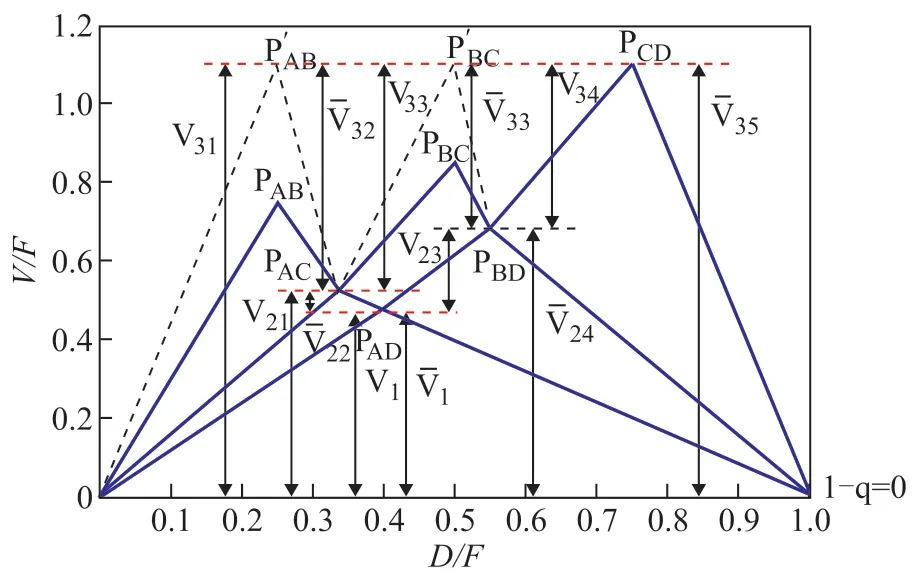
Figure 5 V-min diagram for Sargent column
The V-min method is based on the assumption that columns contain an infinite number of stages when the vapor-liquid phase flow rates are calculated. But the number of distillation column’s stages is limited and the recovery of light components cannot be 100% in actual operation. Therefore the number of distillation column’s stages and the recovery of light components need to be considered or calculated in the shortcut design process.
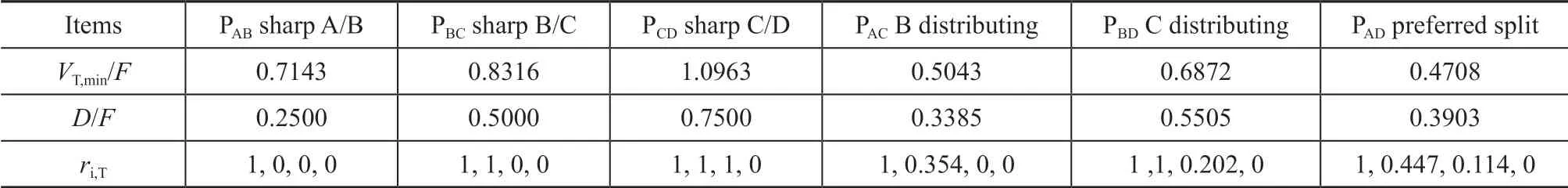
Table 1 Data for peaks and knots in the V-min Diagram
4.2 The Ten column method
Figure 6 shows schematically complete material balance of the Sargent column, which contains all internal flow rates of vapor and liquid streams, and splits of vapor and liquid obtained by the shortcut method shown in Section 3.In order to verify the practicability and reliability of the shortcut calculation method, the deviations between the shortcut calculation method and the rigorous simulation under different feed compositions are compared.
The results of shortcut calculations are inputted into Aspen Plus as the rigorously simulated initial values. The deviations of product purity between the rigorous simulation results and the shortcut calculation results are shown in Table 2. The results show that the maximum deviation of the purity of the main products under different feed compositions is less than 5% for this case. The purity of the methanol at the top of column is close to the rigorous simulation result, and the deviation of the side-line S2 product is larger.
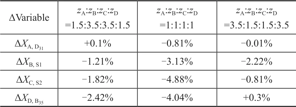
Table 2 The deviations of product purity between the rigorous simulation and the shortcut calculation
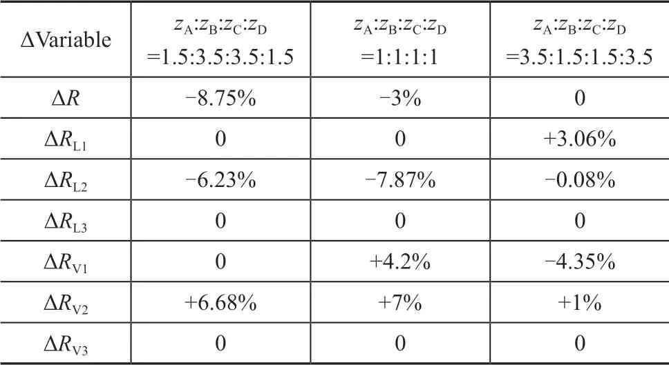
Table 3 Operating parameters deviations between rigorous simulation and the shortcut calculation
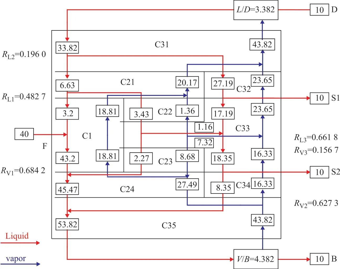
Figure 6 Design parameters of Sargent dividing wall column according to ten column method
Based on the shortcut calculation results, it is necessary to adjust the vapor-liquid phase f low rates (same as adjusting the vapor-liquid distribution ratio) and the reflux ratios of columns until the main products meets the separation requirements, while the theoretical stage number and feed position of each column are unchanged. As shown in Table 3, the deviations of all adjustments in operating parameters are less than 10%. It can be proved that the shortcut calculation of the ten column model proposed in this paper is reliable for the calculation of the Sargent column operating parameters.
5 Optimization of Rigorous Simulation
In order to facilitate the energy saving analysis of the Sargent column, optimization of rigorous simulation is needed. The optimization of rigorous simulation of the ten column model is introduced as follows. The objective is minimizing the energy consumption at a fixed product purity (≥99%), while there are 17 variables that need to be optimized, including the theoretical stage number of ten columns, the feed position and six splits (liquid and vapor). First of all, the number of stages and feed position are determined, because the relation between these variables and the energy consumption is a linear change and is not inter-related. Since the products purities are constraints, there is no such a variable to be changed independently as optimization variables to achieve the minimum energy requirement. In order to allow a fair comparison, the vapor and liquid splits were optimized by using the response surface method. The optimized number of stages and corresponding splits of liquid and vapor are summarized in Figure 7, indicating that 66 theoretical stage numbers are the optimum values. Energy requirements and splits of liquid and vapor are also shown below.
6 Energy Saving Research
For this case, the Sargent column achieves an important 53.01% decrease of reboiler duty and 55.28% decrease of condenser duty as compared to the conventional distillation direct sequence (also called DS), while requiring an equal total number of stages. In other words, the Sargent column consumes only one half of the energy to achieve the same separation as DS. This may be considered an attractive approach which is sufficient to move users to consider accepting the choice associated with building and operation of the Sargent column.
6.1 Analysis of the concentration split

Figure 7 Design parameters of Sargent dividing wall column according to rigorous simulation
The concentration splits of A, B, C, and D in the Sargent column are shown in Figure 8. The concentration splits of the middle components B and C decrease f irst and then increase in the 4th stage nearby, mainly because of the lower feed concentration. It also shows that the higher intermediate component concentration can avoid the energy loss caused by the lower feed concentration. After the separation in the prefractionator, the two mixture streams ABC and BCD go into the upper and lower parts of the middle-column, respectively, to achieve separation again. The middle components B and C go into the maincolumn in the 11th and 34th stages, respectively, when their concentration reaches a maximum. Note that the concentration splits of the middle components B and C decrease f irst and then increase in the coupling positions of the prefractionator and the middle-column, as well as the middle-column and the main-column. The possible reason is that the concentration split is not uniform at the coupling position. The middle components B and C are produced, respectively, when their concentration reaches a maximum in the main-column, while the back-mixing is avoided. The back-mixing effect in a conventional distillation sequence is usually associated with high energy consumption. It can be concluded that the Sargent column enhances the energy saving by eliminating backmixing.
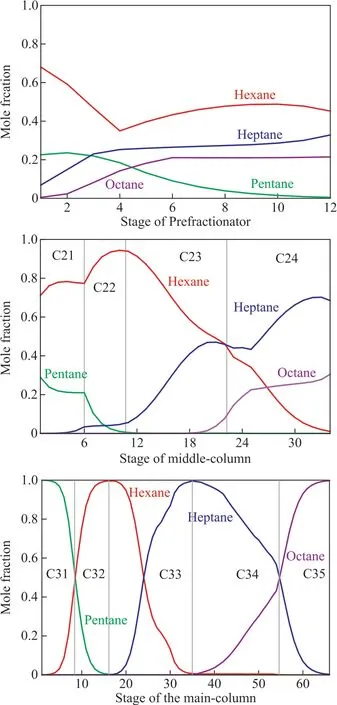
Figure 8 Concentration split of Sargent dividing wall
6.2 The optimal heat transfer position of partition
Currently, the simulation and design of most dividing wall columns are based on a Petlyuk Column in which the heat transfer process across the dividing wall is ignored. Actually, there is heat transfer across the dividing wall which leads to the thermal coupled effect among the prefractionator, the middle-column and the main-column.The reversible T–H profile (CGCC) can be constructed from the target heat load at each stage. This CGCC is used to identify the possibility of side exchanger installation, which can reduce the column exergy loss and also increase the heat integration potential[19]. The thermal coupled effect will be discussed in the following.
Figure 9 shows the exergy loss of streams at each stage in the Sargent column. The feed stage of the prefractionator, the connection position between the prefractionator and the middle-column and the connection position between the middle-column and the main-column take a major proportion of exergy loss resulting from the increase of the irreversible degree that comes with the intense exchange of vapor and liquid streams. The minimum exergy loss appears at the 11th stage of the prefractionator, the second stage of the middle-column, and the 52nd stage of the main-column.
By choosing the stages where the minimum exergy loss locates in the prefractionator, middle-column, and main-column as the demarcation points, some virtual intermediate-condensers are supposed to be installed above the demarcation points and some virtual intermediate-reboilers are supposed to be installed under the demarcation points. The heat transfer between the sections of pre-fractionator’s virtual intermediate condensers and the sections contained in the middlecolumn intermediate-reboilers is advantageous. Figure 10 shows that the third―11th stages in the prefractionator are matched with the ninth―22th stages in the middlecolumn in this case. Similarly, the third―34th stages in the middle-column and the 13th―52nd in the maincolumn are thermally coupled, so it is benef icial to heat transfer.
7 Conclusions
In this paper, a steady-state rigorous distillation model, the ten column model of the Sargent dividing wall column, is established, and a shortcut design method is proposed. The light component recovery from each column section is calculated through the material balance and the Underwood equations, as well as the minimum vapor f low required to complete the respective separation task for each column. The minimum total vapor f low is determined with the aid of the V-min method. WithN(R+1) as the optimization target, the optimal ref lux ratio was found, the Underwood-Fenske-Gilliland-Kirkbride equation was applied during the calculations. All design parameters of the Sargent column through the short-cut design method can be obtained. The case of 4-component alkane mixture was studied, the maximum deviation between the shortcut calculation method and the rigorous simulation of the purity of main products is less than 5% under three different feed compositions. In the rigorous simulation, the operating parameters of the column are adjusted until the main products meet the separation requirements, and the deviation of the adjustment operating parameters are less than 10%, which verifies the practicability and reliability of the shortcut calculation method.

Figure 9 EX loss of Sargent column

Figure 10 Temperature of Sargent column
The energy saving mechanism of the Sargent column was analyzed in terms of concentration split. The results showed that there was no back-mixing in the Sargent column, so the Sargent column has obvious energy saving advantages over DS. The heat transfer through the dividing walls of the Sargent column was considered in this paper. The heat exchange of the virtual heat exchanger in the proper position in the Sargent column makes the Sargent column more energy efficient than the case without considering heat transfer. It can be considered in the future design process.
Acknowledgement:The research project is supported by the High-level Talents Program of Hebei Province (A 2017002032).
- 中國煉油與石油化工的其它文章
- Boosted Biodegradability and Tribological Properties of Mineral Base Oil by Methyl Diethanolamine Fatty Acid Esters
- Extractive Distillation of Methyl Acetate-Methanol Azeotrope Using [DMIM]DMP as Solvent
- Exploring the Degradation Potential of Halomonas Bacteria from Oil-contaminated Marine Environment
- Combined Use of Co-immobilized Lysozyme and Lipase and Chemical Inhibitors in Circulating Cooling Water System
- Phenol Wastewater Degradation by Electrocatalytic Oxidation with RuO2-IrO2-SnO2/Ti Anodes in the High Gravity Field
- Evaluation of Powdered Activated Carbon Treatment Process in Petrochemical Wastewater Purification