The influence of defects in a plasma photonic crystal on the characteristics of microwave transmittance
Ronggang WANG (王榮剛), Ben LI (李犇), Tongkai ZHANG (張桐愷),Jiting OUYANG (歐陽吉庭),5and Yurong SUN (孫玉榮)
1 School of Mechatronical Engineering,Beijing Institute of Technology,Beijing 100081,People’s Republic of China
2 School of Physics, Beijing Institute of Technology, Beijing 100081, People’s Republic of China
3 Beijing Orient Institute of Measurement and Test, Beijing 100094, People’s Republic of China
4 Suzhou TA&A Ultra Clean Technology Co. Ltd, Suzhou 215121, People’s Republic of China
5 Authors to whom any correspondence should be addressed.
Abstract Plasma photonic crystals(PPCs)have been a hot research topic in the band gap(BG)material field in recent years due to their unique advantages, such as the feasibility of changing the parameters and hence the properties of the materials with respect to traditional photonic crystals(PCs).In this paper,we focus mainly on the effects of some types of defects introduced in PPCs on the changes in BG characteristics of microwave (MW) transmittance. The research is carried out using numerical simulation with a one-dimensional finite-difference time-domain (FDTD) method, and six types of defects,including a lattice-constant defect,radii-ratio defect,additional-column defect,column-width defect,plasma-frequency defect,and electron-collision-frequency defect,are concerned.It transpires that introducing a defect in a PPC in different manners may realize the symmetric change,alternative change, shifting, generating, transforming, disappearing, and attenuating of BGs in transmittance spectra,which has great potential for the manufacture of spatiotemporal-controllable MW materials and devices with more feasible modulating functions.
Keywords: plasma photonic crystal, defect mode, microwave transmittance
1. Introduction
The photonic crystal (PC) was proposed by John and Yablonovitch independently in 1987,and is an artificial micro structure formed by periodic arrangement of mediums with different refractive indexes [1-3]. It is also known as a photonic band gap (PBG), which is a spatial periodic structure with large polarization and dispersion characteristics near the band edge and band gap (BG) characteristics of electromagnetic waves (EMWs) [4]. According to the unique characteristics,researchers designed filters,couplers,switches and modulators,and other devices[5,6],which are very effective for controlling EMW radiation sources[7,8].However,when the crystal is fixed,the performance of these conventional PC devices made of PBGs is usually fixed because the main parameters, such as the position, the width and depth of the dielectric constant and the lattice constant,remain unchanged.This drawback greatly influences the further development of PC application. As an alternative, plasma photonic crystals(PPCs) can solve this problem well, and they have been widely considered by scholars at home and abroad [9-12].The PPC was first proposed by Hojoet al[13,14].It is a type of artificial periodic array which introduces plasma gas and alternates with dielectrics. The state and structure of the gas discharge plasma can be changed by adjusting the driving source, voltage, pressure, gas type, and other working conditions, which usually have certain time-varying characteristics [15-17]. It provides a lot of convenience and rich methods for the control and modulation of PBG characteristics [18-20].
In the field of PPCs, the effect of defects in the PPC structure on changing the material properties, and hence the interaction with microwaves (MWs), attracts considerable attention due to the fact that a defect usually provides some additional BGs for special use on the premise of not changing the basic BG character very much.Liuet al[21]simulated the propagation of EMWs in one-dimensional (1D) superlattice PPCs consisting alternately of a homogeneous unmagnetized plasma and dielectric material in terms of defect mode using a finite-difference time-domain (FDTD) algorithm. Konget al[22]reported a novel tunable filter featuring the defect mode of the TE(transverse electric field)wave from 1D PCs doped by magnetized plasma under the matrix transfer method.Qiet al[23]studied the properties of 1D magnetized PPCs with a dielectric defect layer using the transfer matrix method.
In this paper, a 1D FDTD method is used to study the influence of lattice defects on the transmission spectrum BG characteristics of MWs passing through many types of PPCs.Six defects are discussed. Considering that MWs have many applications closely related to real life in the fields of communication, television satellite, radar, networks, and so on,the frequency range of incident MWs is selected as the C and X band (4-12 GHz).
The gas discharge pattern is a typical self-organized PPC.In recent years,gas discharge systems have been well studied in theory and application, but the application research of the system’s mode is not as deep as the theoretical research. The research results of this paper have a certain reference value for its application research. As we all know, the figure structure of a gas discharge will show various continuous phase transitions with the change in control parameters.These structures are affected by the fluctuations of time and space, and often have lattice defects. In this paper, the relation, change mode,and differences in the defective gas discharge mode in MW transmission characteristics are described by comparison.The PPC’s structure constructed in this paper can be used as a good candidate structure similar to the gas discharge mode.
2. Modelling
As a time-domain method, FDTD is widely used in the modelling of computational electrodynamics, including the frequencydomain characteristics of PPCs. The parameters needed for FDTD simulation are mainly the spatial distribution, structure,and dielectric constant of the material. A detailed description of this method and its application in plasma science can be found in[24, 25]. In this paper, a 1D FDTD method is employed to simulate the interaction between the plasma column and MW,and then the BG characteristics of MW transmission in 1D periodic defect mode PPCs are demonstrated.
In this study, figure 1 shows the simulation structure diagram of cylindrical PPCs. Each PPC column is a plasma column covered with a glass layer (or plasma-glass column).The relative permittivity(εr-glass)of the glass layer is 3.8,and the ambient environment is air with the relative permittivity εr-air= 1. The relative permittivity or dielectric function of the plasma is given by
where ω is the angular frequency of the MW, and ωmis the electron-neutral elastic collision, respectively, and ωpis the angular plasma frequency determined by the electron densityneas
whereeis the charge,ε0is the vacuum permittivity,andmeis the mass of an electron.
In addition,to absorb the incident and transmitted waves,the boundary condition along the arrangement direction(x)of the PPC array is set to the perfectly matched layer (PML); to limit MWs within the simulation area,the boundary condition perpendicular to the arrangement direction (y) of the PPC array is set to ‘metal’.
Some related parameters also need to be illustrated. For spatial parameters,L,rp,rc,anddrepresent the distance between the centers of two neighboring columns(or lattice constant),the plasma-column radius,glass-layer thickness,and diameter of the plasma-glass column, respectively. For plasma parameters,fpandvmrepresent the plasma frequency (equivalent to plasma density) and electron-collision frequency, respectively. For BG parameters,fcut,fc,fw,andTdrepresent the cut-off frequency,the central frequency between the starting and ending frequency of a BG, full width of half maximum of a BG, and the BG depth from the baseline to the bottom(absolute value),respectively.Nrepresents the total column number in a PPC,and Nirepresents theith column in a PPC.
3. Results and discussion
In this paper, PPC defect modes are introduced, and their schematic diagrams are shown in figure 2. The definitions of these defect modes will be introduced at the beginning of each subsection.
3.1. Lattice-constant L defect
The lattice-constantLdefect means that at least one plasmadielectric column deviates from its original position and,therefore, the distances from its neighboring columns are different fromL.For simplicity,we define Ni+1(Li-i+1)as the defect column Ni+1with a distanceLi-i+1away from its neighboring column close to the incidence of MWs.

Figure 1. A simulation structure diagram of cylindrical PPCs.
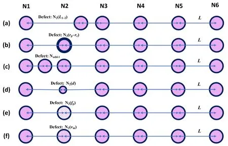
Figure 2.Schematic diagrams of the defect modes in PPCs.
Figure 3 shows the effects ofLdefects of N2-N4at differentLi-i+1. The defects introduce some additional BGs.For all the defect cases compared with the no-defect case,the cut-off frequencyfcutand the positions(orfc)of the two main original BGs almost remain unchanged, with the BG depthsTddecreased to different values. The generation of BG is mainly due to the interference between the EMW reflected by the defect and the traveling EMW. This defect changes these parameters,so some extra BGs will be introduced,but the cutoff frequencyfcutis mainly determined by the plasma frequency (fp); when thefpis settled, it remains unchanged.Through detailed comparison, theTspectra present a symmetry property, being consistent for N2and N5defects(figures 3(a)and(d)),and for N3and N4defects(figures 3(b)and (c)). Moreover, another kind of symmetry property can also be found. TheTof N2(L1-2= 2 and 6 cm) defects are consistent with those of N5(L4-5= 6 and 2 cm) defects,respectively, and so are those of N2(L1-2= 3 and 5 cm) and N5(L4-5= 5 and 3 cm), and the same is also true for the N3and N4defects. This indicates a symmetry property of the PPC withLdefects, i.e. the corresponding defect columns from each edge of the PPC (e.g. N2and N5in the PPC ofN= 6) and with the same distance from its nearer PPC edge(e.g.L1-2= 2 andL4-5= 6 cm) will lead to a sameTcharacter.
Furthermore, for the defects of each Ni, theTspectra ofLi-i+1= 2 and 6 cm, as well asLi-i+1= 3 and 5 cm, are similar to each other, which can be considered as a local symmetry. In figures 2(a) and (d), the defects ofLi-i+1= 2 and 6 cm do not introduce any additional BG but mainly decrease theTdof the two main BGs, while the defects ofLi-i+1= 3 and 5 cm introduce two BGs at each side of the first main BG, withfc= 5.8 and 6.4 GHz andfc= 8.9 and 9.6 GHz, respectively. In figures 2(b) and (c), the defects ofLi-i+1= 2 and 6 cm introduce a BG at each side of the second main BG, withfc= 10.1 and 11.7 GHz,respectively,while the defects ofLi-i+1= 3 and 5 cm introduce a BG offc= 5.3 GHz nearfcut,a BG at each side of the first main BG,withfc= 6.9 and 8.4 GHz, respectively, and a BG offc= 10.1 GHz to the left of the second main BG.
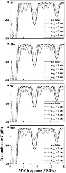
Figure 3.The effect of the L defect on MW transmittance T.(a)Case of N1-N2(L)defect,(b)case of N2-N3(L)defect,(c)case of N3-N4(L)defect, (d) case of N4-N5(L) defect. The simulation condition is column number N = 6, column diameter d = 2 cm, lattice constant L = 4 cm, and plasma frequency fp = 5 GHz.
3.2. Radii-ratio η defect
The radii-ratio η defect means that one of the plasma-dielectric columns in the PPC has a different ratio of plasmacolumn radiusrpover the dielectric tube thicknessrcfrom the others. We use Ni(rp-rc) to represent the η defect configured to theith column with values ofrpandrc.
Figure 4 shows the effect of the η defect on the MW transmittanceT. Figures 4(a) and (b) give theTspectra with the defect configured to N1of different groups ofrpandrc.There is no additional BG introduced, but just the deepening of the two main BGs from N1(10-0)(the dielectric tube being removed) until N1(5-5) (figure 3(a)). For N1(5-5), an additional BG (fc= 9.9 GHz) appears to the left of the second main BG. Withrpdecreasing (orrcincreasing) further, this new BG shift towards a lower frequency with its depth varies a little,and another new BG(around 11.5 GHz)appears to the right of the second main BG from N1(4-6) and deepens gradually afterwards (figure 3(b)). Despite some detailed differences, the results in figures 3(c)-(f) are largely consistent with those in figures 3(a) and (b). Furthermore, the symmetry property in figure 3 is still valid here,i.e.the results under defects on N4, N5, and N6corresponds to those on N3,N2,and N1,respectively.In general,configuring the defect on any one of the columns of the PPC will result in a similar result.
3.3. Additional-column Nadd defect
The additional-column Nadddefect means inserting at least one additional plasma-dielectric column at the center of the interval between neighboring columns of the original perfect PPC with columns evenly spaced.We use Nadd-ito represent a column defect placed in the interval between column Niand Ni+1. The defect column is the same as the others.
Figure 5(a) shows the effect of one Nadddefect on the MW transmittanceT. It is found that, with the defect column inserted in whichever interval: (1) theTspectra are generally consistent with each other,indicating that inserting the defect column in whichever interval makes no difference, (2) the defect does not change the number and position of the original BGs, and (3) the defect deepens and elevates the BGs alternatively with respect to the those of the no-defect case.Introducing two Nadddefects does not change the ‘a(chǎn)lternating’property, but deepens or elevates the BGs to a larger extent(figure 5(b)).
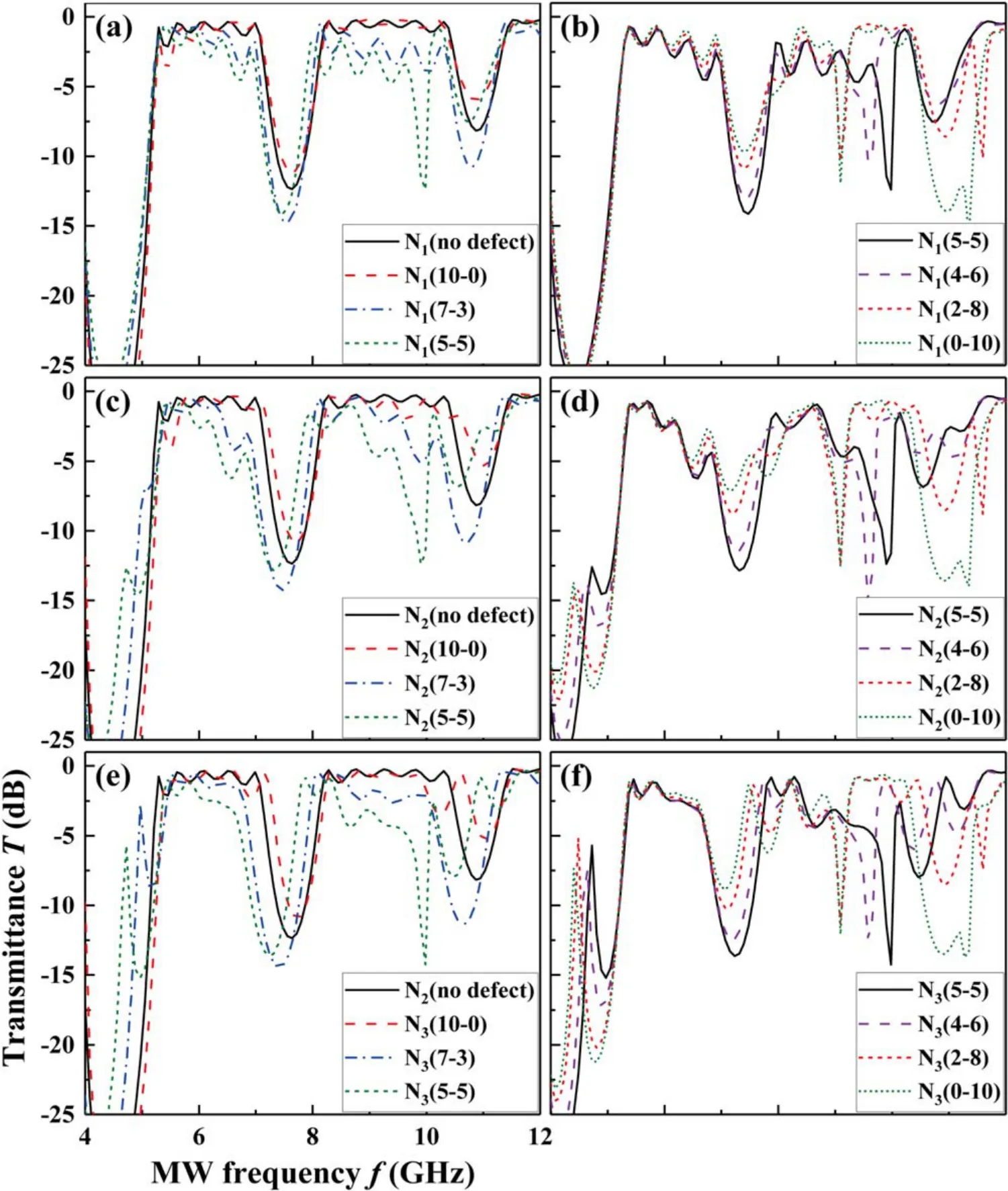
Figure 4.The effect of the η defect on MW transmittance T.(a)and(b)Case of N1(η)defect,(c)and(d)case of N2(η)defect,(e)and(f)case of N3(η) defect. The simulation condition is column number N = 6, column diameter d = 2 cm, lattice constant L = 4 cm, and plasma frequency fp = 5 GHz. The rp and rc is constant at 9 mm and 1 mm, respectively, except for the defect column.
The generation of BG is mainly due to the interference between the EMW reflected by the defect and the traveling EMW.This defect changes the number of plasma columnsN.We found that whenNis greater than six, the new plasma columns cannot introduce new obvious BG, and the peak value of transmittance decreases with the increase inN. This is mainly because the plasma is a type of dissipative medium.Its dielectric constant and refractive index are related to the frequency of the incident EMW. It not only filters the EMW itself,but also absorbs the energy of the incident EMW due to the collision of the plasma when the frequency of the incident EMW is higher than the frequency of the plasma.The energy of the EMW is converted into that of the plasma’s internal energy.With the increase in the period constantN,the energy loss of the EMW in plasma increases accordingly, therefore,only increasing the period parameterNcannot introduce a new obvious BG, but it will affect the peak of the transmittance.
3.4. Column-width d defect
The column-widthddefect means one plasma-dielectric column has a differentd(along thex-axis) from the others.We use the term Ni(d) to represent the column Niserving as the defect with a width ofd.The PPC of a rectangular column array is employed to study the effect of theddefect on theTspectrum. It is found in simulation that the change inTcharacteristics will be very different when configuring theddefect to each column.
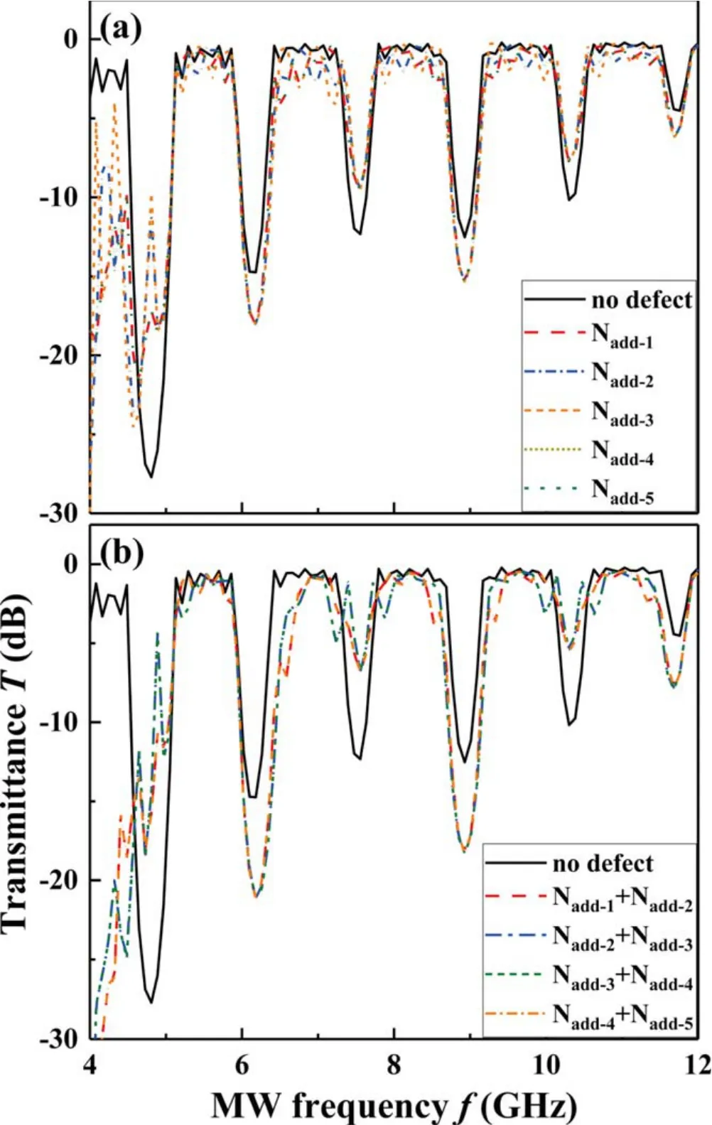
Figure 5.The effects of the Nadd defect on MW transmittance T.The defect column is the same as the others. (a) The case of one Nadd defect,and(b)the case of two Nadd defects.The simulation condition is column number N = 6 (exclusive of defect column(s)), column diameter d = 2 cm, lattice constant L = 10 cm, and plasma frequency fp = 5 GHz.
Figures 6(a) and (b) show the effect of the N2(d) defect on theTspectrum.Atd= 0.5,1,2.5,and 3 cm(figure 6(a)),the defect does not change the BG character of theTspectrum but just results in varied BG depths. Whendincreases to 3.5 and 4 cm(figure 6(b)),the second passing band and forbidden band in the range of 7-10 GHz transform into a group of small BGs.For the N3(d)defect,withddecreasing from 2 cm,a new BG of 7 GHz develops to the right of the first main BG(see the case of N3(d= 1 cm) in figure 6(c)), and then another two BGs of 8.3 and 9.6 GHz are born at the sides of the second main BG (see the case of N3(d= 0.5 cm) in figure 5(c)). For the N3(d= 2.5-4 cm) defect (figure 5(d)),the remarkable change in theTspectrum with respect to the case of‘no defect’lies in the range of 8-10 GHz.The second forbidden band, associated with partial passing bands, transforms into three BGs of 8.4,9,and 9.6 GHz(like the case of N3(d= 0.5 cm)), among which the first one at 8.4 GHz is deepened, the second at 9 GHz is elevated significantly to have the second depth, and the third one at 9.6 GHz has the smallest depth for the entire time and keeps being elevated until disappearing withdincreasing. The symmetry property is still valid, namely, theTspectra under N4(d) and N5(d)defects corresponding to those under N3(d)and N2(d)defects.
3.5. Plasma-frequency fp defect and electron-collisionfrequency νm defect
It has been confirmed that thefpaffectsTd,fc,andfwof BGs,while the introduction of νmleads to the attenuation of the wholeTspectrum. In general, increasingfpand νmwill both result inTattenuation, although in different ways. In this subsection,the effects offpand νmdefects onTcharacteristics are studied, respectively.
Thefp(or νm) defect means configuring the plasma (or electron collision) frequency of one plasma-dielectric column different from that of the others in the PPC.We use Ni(fp)(or Ni(νm))to represent the column Niserving as the defect with a plasma (or electron collision) frequency offp(or νm). It is determined in simulation that configuring thefp(or νm) defect to any one of the columns in the PPC makes no difference and,therefore,figures 7 and 8,as an example,present the effects of N1(fp) and N1(νm) defects onTcharacteristics, respectively.
When the plasma frequency of the defect is configured as lower (e.g. N1(fp= 1 GHz)) and not much higher (e.g.N1(νm= 6 GHz))than that(5 GHz)of the other columns in the PPC, theTspectra remain unchanged basically with respect to that of the no-defect case. With thefpof the defect increasing further (e.g. N1(νm= 8 and 9 GHz)), theTspectrum presents obvious attenuation with the BG shifting no more than 0.15 GHz. The attenuation effect of the defect is strengthened with the increase infp. The main reason for the above phenomenon is when the frequency of the incident EMW is close tofp,resonance attenuation is achieved, and the attenuation of the plasma to the EMW is very large. When the frequency of the incident EMW is greater than the plasma frequency,the attenuation of the plasma to the EMW is mainly collision absorption,and the attenuation of the EMW is far less than the resonance attenuation; at this time, the transmittance will increase.
The introduction of the N1(νm) defect results in a slight attenuation of theTspectrum only.The parameter of νmonly affects the properties of the PC from the angle of energy attenuation of the EMW, and does not change the band structure significantly. The electrons in the plasma are accelerated by the electric field of the EMW, absorbing the energy of the EMW, and passing the energy to the neutral particles and ions through the collision.When νmincreases to a certain value, the transmission peak hardly increases with the increase in the collision frequency. But the interesting phenomenon is that theTattenuation changes in different ways with νmincreasing. It will be strengthened when νm≤fp,but weakened when νm>fp.In general,bothfpand νmdefects can serve as a kind of fine modulation of MW attenuation without changing the basic BG character.
4. Conclusions
To summarize,the effects of different kinds of defect modes on the BG characteristics in transmittance spectra of MWs passing through 1D periodic PPCs are investigated in numerical simulation using an FDTD method. For the lattice-constant defect,several kinds of symmetricity among different cases are obtained from different aspects. The radii-ratio defect introduces additional BGs and generates BG shifting with the related parameters changing. The additional-column defect does not change the basic BG characteristics (i.e. BG positions and widths), but deepens and elevates the BG depths in an alternative manner with respect to those in the no-defect case. The column-width defect provides the generation, transformation, and disappearance of additional BGs with the related parameters changing. Both the plasma frequency and the electron-collision frequency lead to the attenuation of transmittance spectra without the basic BG characters changing much. For the plasma-frequency defect, the spectra do not attenuate much when the defective frequency is not very high,but will attenuate much faster if the defective frequency is very high. For the electron-collision-frequency defect, the spectra also attenuate,but not so significantly.The interesting phenomenon is that,with the defective frequency increasing, the attenuation will be strengthened when νm≤fpbut weakened when νm>fp.

Figure 6.The effect of the d defect on MW transmittance T.(a)and(b)Case of N2(d)defect,(c)and(d)case of N3(d)defect.The simulation condition is column number N = 6, column width d = 2 cm (exclusive of the defect column), column height h = 2 cm, lattice constant L = 5 cm, and plasma frequency fp = 5 GHz.
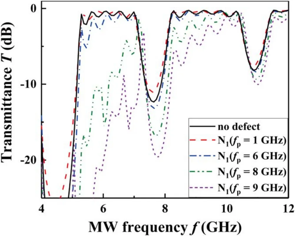
Figure 7. The effect of the fp defect on MW transmittance T. The simulation condition is column number N = 6, column diameter d = 2 cm, lattice constant L = 4 cm, and plasma frequency fp = 5 GHz (exclusive of the defect column).
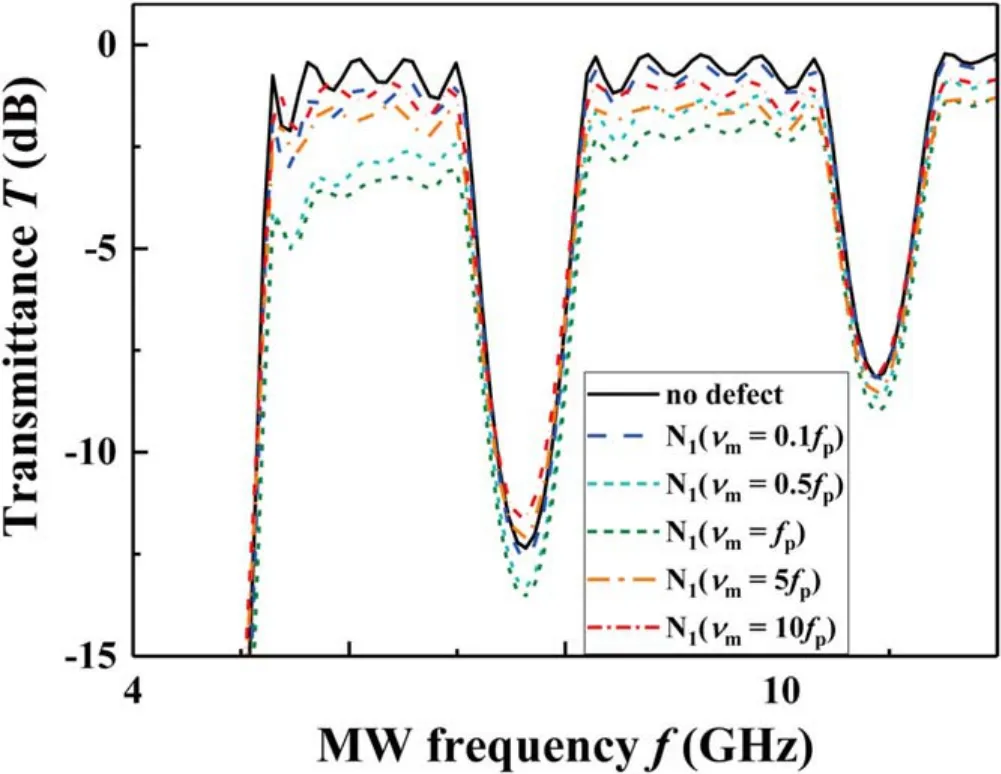
Figure 8.The effect of the νm defect on MW transmittance T. The simulation condition is column number N = 6,column diameter d = 2 cm, lattice constant L = 4 cm, and plasma frequency fp = 5 GHz.
In general,introducing a defect in a PPC in different ways may realize the symmetric change,alternative change,shifting,generating,transforming,disappearing,and attenuating of BGs in transmittance spectra, which has great potential for the manufacture of spatiotemporal-controllable MW materials and devices with more feasible modulating functions.
Acknowledgments
This work was partly supported by National Natural Science Foundation of China (No. 11475019).
ORCID iDs
 Plasma Science and Technology2020年8期
- Plasma Science and Technology的其它文章
- Design and control of the accelerator grid power supply-conversion system applied to CFETR N-NBI prototype
- Identification of heavy metal-contaminated Tegillarca granosa using laser-induced breakdown spectroscopy and linear regression for classification
- Automated electron temperature fitting of Langmuir probe I-V trace in plasmas with multiple Maxwellian EEDFs
- Measurement of tungsten impurity spectra with a two-crystal X-ray crystal spectrometer on EAST
- Multi-scale interaction between tearing modes and micro-turbulence in the HL-2A plasmas
