Application of wellhead suction anchor technology in the second production test of natural gas hydrates in the South China Sea
Bo Li , Bei-ei Kou ,*, Bin Li , Jing Li , Jing Zeng , Qing-lei Niu, , Yu-tao Shao, , Ke-wei Zhang Hao-yu Yu Ying-sheng Wang
a Guangzhou Marine Geological Survey, China Geological Survey, Guangzhou 510075, China
b National Engineering Research Center of Gas Hydrate Exploration and Development, Guangzhou 510075, China
c Southern Marine Science and Engineering Guangdong Laboratory (Guangzhou), Guangzhou 511458, China
d Institute of Exploration Techniques, China Academy of Geological Sciences, Langfang 065000, China
Keywords:
Wellhead suction anchor
Conductor jetting
Marine NGHs
Production test
NGHs exploration trial engineering
Oil and gas exploration engineering
South China Sea
A B S T R A C T
Traditional suction anchor technology is mainly used in the fields of subsea structure bearing foundations,single-point mooring systems and offshore wind power.It is characterized by providing sufficient lateral and vertical bearing capacities and lateral bending moment.The anchor structure of a traditional suction anchor structure is improved with wellhead suction anchor technology, where a central pipe is added as a channel for drilling and completion operations.To solve the technical problems of a low wellhead bearing capacity, shallow built-up depth, and limited application of conductor jetting in the second production test of natural gas hydrates (NGHs) in the South China Sea (SCS), the China Geological Survey (CGS) took the lead in independently designing and manufacturing a wellhead suction anchor, which fulfilled the requirements of the production test.This novel anchor was successfully implemented in the second production test for the first time, providing a stable wellhead foundation for the success of the second production test of NGHs in the SCS.
1.Introduction
The theory of suction anchor technology was introduced in the 1960s (Goodman LJ et al., 1961), and the first formal application was designed by Single Bouy Mooring Inc.in 1980 as a mooring anchor for oil storage equipment in the Denmark GORM oilfield in the North Sea of Europe (Senpere D et al., 1982).In the following decades, suction anchor technology rapidly evolved, resulting in the gradual establishment of a scientific and effective technical system(Xu JZ et al., 1995; Xu JZ et al., 2002; Wang LQ et al., 2011;Wang Z et al., 2012).In 2011, Neodrill AS and Det Norske Oljeselskap ASA jointly proposed a new type of suction anchor called the conductor anchor node (CAN), namely, the wellhead suction anchor.The demonstration applications were implemented at water depths ranging from 270 m to 1150 m at a Norwegian Sea well site.The inclinations were less than 1° (Sivertsen T et al., 2011).Compared with the conventional suction anchor, for a wellhead suction anchor, the addition of the central pipe is the most obvious structural difference and the main functional difference.The new suction anchor can provide a sufficient and safe bearing capacity and bear the weight of the underwater blowout preventer or the underwater Christmas tree.At the same time, it can help avoid the fatigue failure that may occur during the drilling stage and reduce the amount of drilling cuttings and cement involved, the latter of which is more important for protecting sensitive marine environments and performing riserless drilling.In 2014,Neodrill AS implemented the on-site installation of a wellhead suction anchor at a depth of 1444 m for a deepwater exploratory well that adopted riserless drilling at Centrica's Ivory well in the Norwegian Sea, with a final installation inclination of 0.4° (Kopperud E et al., 2017).In 2018, Kan CB et al.(2018) used SIMULIA Abaqus (Dassault Systèmes,Paris, France) to conduct a numerical simulation study on the load-bearing characteristics of a composite conductor structure composed of a deepwater conductor and a suction anchor foundation.The results showed that the suction anchor foundation increased the contact area of the composite conductor structure with the soil, thereby improving the overall load-bearing characteristics of the whole structure,including the vertical bearing capacity, lateral bearing capacity, and bending moment bearing capacity.In 2019, Guo R (2019) analyzed the mechanical behavior of wellhead equipment with a wellhead suction anchor.The vertical bearing capacity was derived and calculated theoretically based on the pile foundation theory.The lateral bearing capacity was simulated by finite element analysis using SIMULIA Abaqus.The mechanical response on riser joints under cyclic loading was also analyzed.
The water depth of the NGH production test field in the Shenhu area of the northern SCS is 1200 m to 1300 m, and the hydrate reservoir depth is 203 m to 277 m below the seabed (Li JF et al., 2018).In 2017, the first production test of marine NGHs in China maintained stable gas production for 60 days with a vertical well, and the average gas production was more than 10000 m3per day.Conductor jetting was implemented to obtain a sufficient wellhead bearing capacity(Li JF et al., 2018).In the second production test, to further increase the gas production and support the commercial production of marine NGHs, the production test headquarters of CGS decided to use horizontal well for the second production test of marine NGHs (Ye JL et al., 2020).Because NGHs form in shallow formations in deepwater areas, the implementation of horizontal well drilling technology encountered the challenges of shallow kick-off points and poor wellhead stability.Meanwhile, simple conductor jetting technology cannot provide a sufficient wellhead bearing capacity to satisfy the wellbore trajectory design of horizontal well.However, the first application of wellhead suction anchor technology in China solved the problems above.It helped to effectively improve the vertical and horizontal bearing capacities of the wellhead of shallow horizontal well and provided greater vertical space to improve the vertical positioning of the kick-off point and reduce the build-up rate,which guaranteed a stable wellhead foundation for the successful implementation of the second production test of marine NGHs in China.
2.Wellhead suction anchor technology
Wellhead suction anchor technology is a wellhead stabilization technology that has been proposed and developed rapidly in recent years.The anchor structure of a traditional suction anchor structure is improved with wellhead suction anchor technology, where a central pipe is added to provide a sufficient bearing capacity as well as a channel for drilling and completion operations (Fig.1).
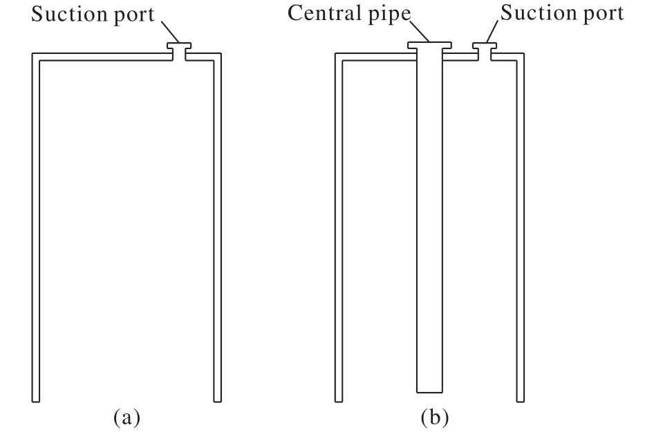
Fig.1.Schematic diagram of structure comparison between a traditional suction anchor (a) and wellhead suction anchor (b).
2.1.Design and penetration analysis of the wellhead suction anchor
The design of the wellhead suction anchor mainly includes the bearing capacity design and overall size design.The bearing capacity provided by the wellhead suction anchor is affected by the size of the wellhead suction anchor, the structural arrangement of the anchor, and the mechanical properties of the topsoil of the construction block.Usually,the design of wellhead suction anchors starts from determining the loads applied to the wellhead suction anchors,including vertical loads, lateral loads and bending moment loads.The safety factor under extreme conditions should be considered.At present, there are mainly API methods (API RP 2A-WSD, 2014; API RP 2GEO, 2014) and DNV methods(DNVGL RP C212, 2017; DNVGL RP E303, 2017) that can be referred to for the calculation of bearing capacity and penetration analysis.
Based on soil mechanics and pile foundation theory, the vertical bearing capacity of the wellhead suction anchor is mainly the friction force generated between the topsoil and the sidewall of the wellhead suction anchor and the soil supporting reaction force generated by the soil at the bottom end of the wellhead suction anchor (Fig.2).Therefore, the vertical ultimate bearing capacity of the wellhead suction anchor can be expressed as:
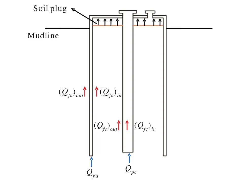
Fig.2.Schematic diagram of the force loading on the wellhead suction anchor.Note: The black arrow indicates the supporting reaction force of the soil to the top plate of the wellhead suction anchor when the inside of the wellhead suction anchor is filled with soil plugs.

whereQuis the vertical ultimate bearing capacity of the wellhead suction anchor, kN;QfaandQfcare the frictional forces generated by the sidewallsof the wellhead suction anchor barrel and the central pipe, respectively, kN;QpaandQpcare the soil supporting reaction forces at the bottom ends of the wellhead suction anchor cylinder and the central pipe,respectively, kN;faandfcare the ultimate friction forces per unit area of the wellhead suctionanchor cylinder and the central pipe in contact with the soil, respectively, kPa;AsaandAscare the areas of the sidewallof the wellhead suction anchor cylinder and the central pipe in contact with the soil,respectively, m2;qaandqcare the ultimate soil supporting reaction forces per unit area at the bottom ends of the wellhead suction anchor cylinder and the central pipe,respectively, kPa; andApaandApcare the bottom end areas of the wellhead suction anchor cylinder and the central pipe,respectively, m2.
When the soil plug inside the wellhead suction anchor fills the entire internal space of the wellhead suction anchor, the action area of the soil supporting reaction force at the bottom of the wellhead suction anchor can be considered the crosssectional area of the entire wellhead suction anchor.At this time, the inner sidewall of the wellhead suction anchor and the outer sidewall of the central pipe are considered to be frictionless.
The wellhead suction anchor has internal structures, such as reinforcing ribs.During the installation process, the reinforcing ribs and other structures may disturb the soil inside the wellhead suction anchor cylinder, which may result in a reduction in the soil strength.Therefore, usually, the soil strength inside the wellhead suction anchor should not be greater than the soil strength outside, which should be adjusted according to actual needs.At the same time, in practical applications, to improve the safety factor of the wellhead suction anchor, the friction force at the sidewall and the supporting reaction force at the bottom end between the topsoil and the central pipe can be ignored.
For the penetration analysis, the same set of theories and calculation formulas is used to calculate the vertical ultimate bearing capacity.However, the vertical ultimate bearing capacity is calculated using the lower estimation (LE) or the best estimation (BE) of the soil strength profile, while the higher estimation (HE) of the soil strength profile is used in the penetration analysis on the condition that the topsoil is cohesive.
2.2.Comparison with conductor jetting technology
Conductor jetting technology is a relatively common,mature and reliable wellhead stabilization technology in deepwater oil and gas development.A set of systems for vertical bearing capacity calculations has been established,which is generally accepted by the deepwater oil and gas industry (Evans TG et al., 2002; Mackenzie B et al., 2012;Prasertamporn P, 2016; Syazwan M et al., 2016;Wei HS et al.,2019; Zhang PW et al., 2020).The calculation methods of the vertical bearing capacity of the conductor and the minimum mud penetration depth are as follows.
(i) Vertical ultimate bearing capacity of conductor
According to the API specification, the calculation formula of the ultimate bearing capacity of the conductor is the same as that of the wellhead suction anchor in principle.

Qconis the vertical ultimate bearing capacity of the conductor, kN;Qfconis the frictional force on the sidewall of the conductor, kN;Qpconis the soil supporting reaction force at the bottom end of the conductor, kN;fconis the frictional force per unit area on the sidewall of the conductor, kPa;Asconis the area of the sidewall of the conductor, m2;quconis the soil supporting reaction force perunit area at the bottom end of the conductor, kPa; andApconis the area at the bottom end of the conductor, m2.In practical applications, the soil supporting reaction force at the bottom end is often ignored.
(ii) The initial bearing capacity of the conductor

Q0is the initial bearing capacity of the conductor(t=0.01d);WOBlastis the weight on bit (WOB) for the final measurement (the weight acting on drill bit when the conductor reaches final penetration depth);Ris the WOB utilization rate (ranging from 0.8 to 1.0);WMud?Matis the floating weight of the anti-sinking board;WLPWHis the floating weight of the low-pressure wellhead (LPWH);wJPis the floating weight of the jetting string per unit length;WCADAis the floating weight of the cam-actuated drill ahead (CADA)tools;w1is the floating weight of the upper conductor per unit length;L1is the length of the upper conductor;w2is the floating weight of the lower conductor per unit length; andLis the conductor penetration depth.
(iii) Real-time bearing capacity of the conductor
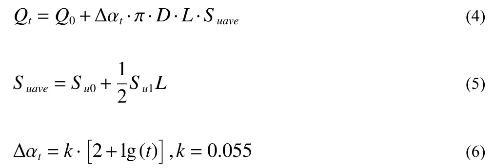
Assuming that the undrained shear strength of soil varies uniformly with depth, the following laws are met:

Assume that there is a wellhead suction anchor with a diameter of 6 m, a height of 12 m, and a wall thickness of 1 in which the internal space is not filled with a soil plug (ignoring the soil supporting reaction force at the bottom of the cylinder and the bearing capacity of the central pipe).Its ultimate bearing capacity is approximately 5606.78 kN, according to the formula above.
To achieve the same ultimate bearing capacity, for a conductor with a diameter of 36 in and a wall thickness of 1 in, the jetting depth into mud is calculated to be approximately 34.60 m, which is approximately three times the height of the wellhead suction anchor assumed before.
In the first production test of NGHs in the SCS, a vertical well was adopted, and conductor jetting technology was used to ensure the stability of the wellhead.The penetration depth of the conductor was calculated to be 71.22 m according to the real-time bearing capacity under extreme working conditions and the wellhead load value (Li WL et al., 2019).For a more intuitive comparison, this paper assumes that a horizontal well was adopted in the first production test and that the penetration depth of the conductor satisfied the wellhead stability.At the same time, it is assumed that the topsoil strength profile in the SCS conforms to the variation law of Equation (6).Thus, a wellhead suction anchor with a diameter of 6 m and a height of 12 m can reach an ultimate bearing capacity equal to that of the upper conductor with a length of 34.6 m, as calculated with Hailiburton Landmark(Hailiburton Co., Houston, USA).A safety distance of 10 m is reserved for the kick-off point under the last section of the conductor, while the horizontal section is located at the same depth below the mudline.The comparison of the wellbore trajectories of horizontal wells with and without a wellhead suction anchor is shown in Fig.3, and the key wellbore trajectory parameters are shown in Table 1.
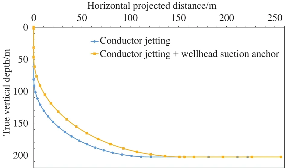
Fig.3.Comparison of horizontal wellbore trajectories with and without a wellhead suction anchor.
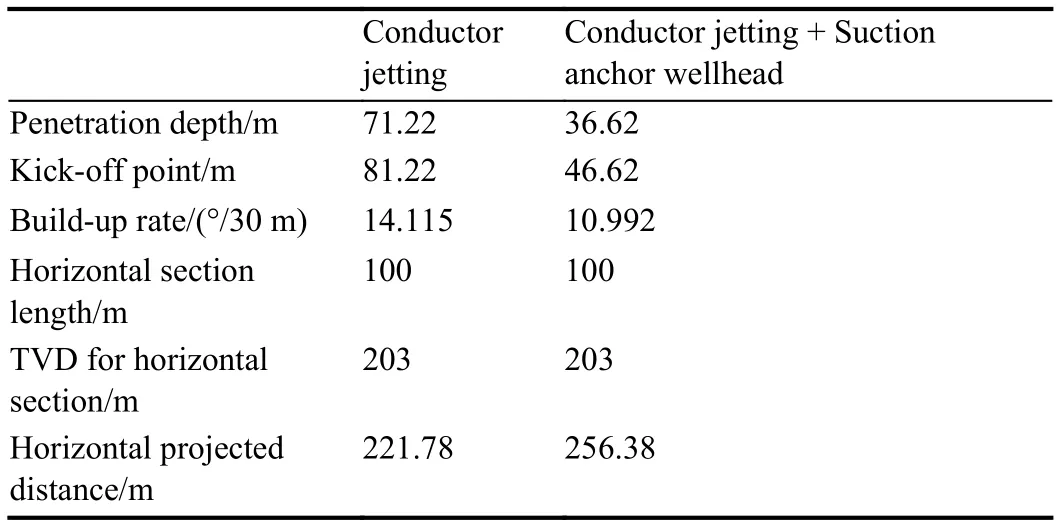
Table 1.Key wellbore trajectory parameter comparison.
Obviously, under the condition of providing the same ultimate bearing capacity, the mud penetration depth of the wellhead suction anchor is much smaller than that with only conductor jetting.Wellhead suction anchor technology has obvious advantages, which can save vertical space and provide a greater choice for the depth of the kick-off point.The improvement in the kick-off point can reduce the dogleg of the horizontal wellbore trajectory, increase the passing ability of downhole tools, and improve the success rate of the drilling and completion of shallow horizontal wells in deepwater areas.
2.3.Common follow-up operations of wellhead suction anchors
The installation process of the wellhead suction anchor is the same as that of the traditional suction anchor, including the self-weight penetration stage and the underpressure penetration stage (Elgharbawy SL et al., 1999; Erbrich CT et al., 1999; Dendani H et al., 2002; Nazari M et al., 2020).The wellhead suction anchor is usually installed offshore by an engineering ship.The engineering ship should be equipped with a dynamic positioning system and an active heave compensation crane to ensure that the ship's position is relatively fixed during the installation of the wellhead suction anchor and reduce the impact of surge on the wellhead suction anchor system.
After the wellhead suction anchor is placed, there are usually two follow-up operations: one is to position the surface conductor by means of jetting down the conductor; the other is to position the surface conductor by drilling with a drill bit and cementing the well.Instances of using the wellhead suction anchor with conductor jetting in the construction of deepwater oil and gas wells are increasing(Sivertsen T et al., 2011; Kopperud E et al., 2017; Ye JL et al., 2020).
3.Wellhead suction anchor field implementation
3.1.Design of the single-pile wellhead suction anchor
In the second production test of marine NGHs in the northern SCS, the single-pile wellhead suction anchor used is 6.5 m in diameter and 12 m in height and has a total weight of 96 t in air (Ye JL et al., 2020).According to the mechanical parameters of the topsoil in the production test area of the Shenhu block, the vertical ultimate bearing capacity of the wellhead suction anchor with a diameter of 6.5 m and a height of 12 m was calculated to be 5798 kN on the condition that the wellhead suction anchor was filled with internal soil plugs.Meanwhile, a three-dimensional numerical model was established with SIMULIA Abaqus (Park JS et al., 2015; Han I et al., 2016; Huang Z et al., 2021), and the finite element numerical simulation of the vertical ultimate bearing capacity was carried out.The simulation results showed that the vertical ultimate bearing capacity was 6134 kN.Obviously,the theoretical calculation result was similar to the numerical simulation calculation result.The design drawing and photograph of the single-pile wellhead suction anchor are shown in Fig.4.
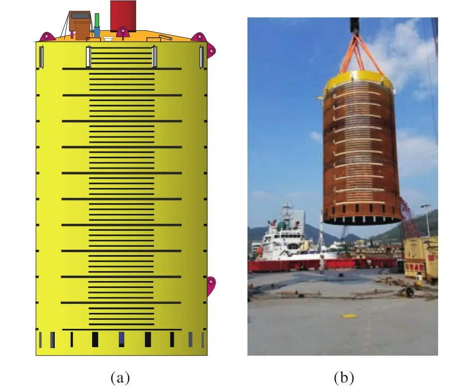
Fig.4.(a) Design drawing and (b) photograph of a single-pile wellhead suction anchor.
3.2.Offshore installation of a single-pile wellhead suction anchor
The offshore installation of the single-pile wellhead suction anchor was carried out by an engineering ship.The operation procedures of the installation process successively included arranging the subsea positioning floating ball,releasing the wellhead suction anchor, lifting up, passing through the splash zone (Fig.5 and Supplementary video material), exhausting gas and lowering into the water,lowering to near the mud line, lowering down into the mud after positioning, self-weight penetration, underpressure penetration, monitoring equipment and suction pump recovery, and well position retesting.After the wellhead suction anchor was installed successfully, conductor jetting was implemented to install the surface conductor.
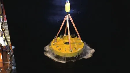
Fig.5.The single-pile wellhead suction anchor passing through the splash zone.
4.Field data and analysis
Fig.6 shows the variation curve of the hook load and penetration velocity with mud penetration depth during the installation of the wellhead suction anchor on site.This figure supports the following observations:
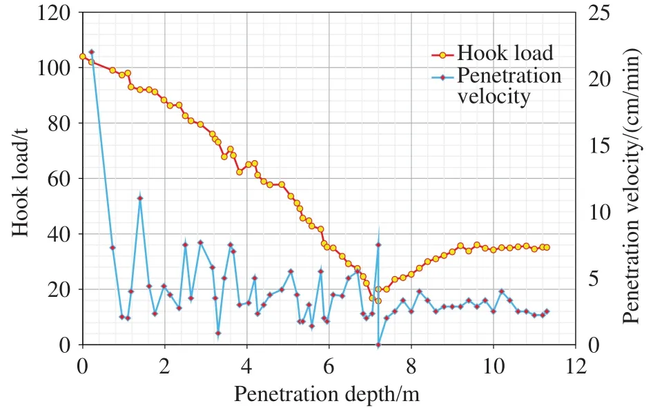
Fig.6.Variation curve of the hook load and penetration velocity with penetration depth.
(1) After the wellhead suction anchor reached the mudline, the self-weight penetration stage started.Since the soil near the mudline was very soft, the penetration resistance of the wellhead suction anchor was very small, and the penetration speed was relatively fast.With increasing penetration depth, the shear strength of the soil and the contact area between the wellhead suction anchor and the soil gradually increased.Therefore, the penetration resistance gradually increased, while the penetration speed gradually decreased.
(2) The penetration depth of the self-weight penetration stage was 7.2 m below the mudline.From 0 m to 7.2 m, the hook hanging load was decreased in increments of approximately 5 t to 10 t, and the self-weight of the wellhead suction anchor was gradually released.Each time the penetration depth increased 1 m, the penetration process was paused for approximately 5 minutes.The self-weight penetration stage lasted until the hook hanging load dropped to 15.8 t.Because the release of the hook hanging load was manually controlled, the release speed varied, resulting in large fluctuations in the self-weight penetration speed.However, generally, the penetration speed gradually decreased with increasing penetration depth.
(3) After the self-weight penetration stage, the exhaust valve was closed, and the suction pump was opened with a remotely operated vehicle (ROV), which started the underpressure penetration stage.The hook load was controlled to gradually increase to approximately 30 t.The considerable seawater pressure generated by the pressure difference inside and outside the cylinder acted on the top of the anchor so that the wellhead suction anchor continued to penetrate into the formation.The ROV driver controlled the suction pump displacement, and the crane operator controlled the hook lowering speed in a cooperative way so that the penetration speed of the wellhead suction anchor was basically controlled between 3 cm/min and 5 cm/min.
(4) After the installation was completed (Fig.7), it was confirmed that the final positioning accuracy of the single-pile wellhead suction anchor was 0.88 m and that the verticality was 0.17°.The self-weight penetration depth was 7.2 m, the final penetration depth was 11.3 m, and the maximum underpressure was 0.159 MPa.
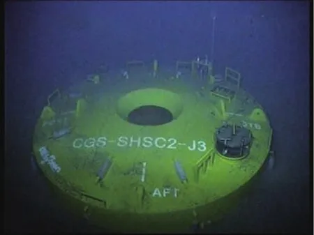
Fig.7.The single-pile wellhead suction anchor installed in place.
5.Conclusions
The key findings of this study are as follows:
(i) The wellhead suction anchor has a large contact area with the soil, which can provide a sufficiently large bearing capacity and a channel for drilling and completion operations.Thus, the wellhead suction anchor has great application prospects in the development of deepwater oil and gas and marine NGHs.
(ii) Compared with conductor jetting technology, wellhead suction anchor technology can improve the kick-off point depth and enlarge the vertical deflection space when providing an equal bearing capacity, which is more conducive to the optimization of horizontal wellbore trajectory.
(iii) The first application of wellhead suction anchor technology in China has achieved remarkable success.The combination of wellhead suction anchor technology and conductor jetting technology further increased the wellhead bearing capacity, which provided a stable wellhead foundation for the success of the second production test of marine NGHs in the SCS.
CRediT authorship contribution statement
Bo Li, Bei-bei Kou, Qing-lei Niu, and Yu-tao Shao carried out the practical application offshore, recorded the data presented, and contributed to the interpretation of the results.Bo Li took the lead in writing the manuscript and performed the computations.Bin Li helped with the Haliburton Landmark.All authors provided critical feedback and contributed to the final manuscript.
Declaration of competing interest
The authors declare no conflicts of interest.
Acknowledgement
This research was jointly supported by the Natural Gas Hydrate Exploration and Production Test Project of China Geological Survey (DD20221700), Key-Area Research and Development Program of Guangdong Province(2020B1111030003), and Key Special Project for Introduced Talents Team of Southern Marine Science and Engineering Guangdong Laboratory (Guangzhou) (GML2019ZD0504).
Supplementary dataset
Supplementary video material to this article can be found online at doi: 10.31035/cg2022027.
- China Geology的其它文章
- China achieved fruitful results in oil-shale gas-coalbed methane exploration and development in 2021
- Formation mechanism, experimental method, and property characterization of graindisplacing methane hydrates in marine sediment: A review
- Molecular simulation studies on natural gas hydrates nucleation and growth: A review
- Distributed optical fiber acoustic sensor for in situ monitoring of marine natural gas hydrates production for the first time in the Shenhu Area, China
- Experimental investigation of hydrate formation in water-dominated pipeline and its influential factors
- Stability analysis of seabed strata and casing structure during the natural gas hydrates exploitation by depressurization in horizontal wells in South China Sea

