Design method of reusable reciprocal invisibility and phantom device
Cheng-Fu Yang(楊成福), Li-Jun Yun(云利軍), and Jun-Wei Li(李俊瑋)
School of Information Science and Engineering,Yunnan Normal University,Kunming 650500,China
Keywords: transformation optics,reciprocal cloak,illusion,invisibility
1. Introduction
Invisibility is one of the most desired skills of human beings. The traditional invisibility technology is mainly to attache the absorbing material to the surface of the object,or designs the object into a special geometric structure to weaken the reflected electromagnetic wave, thereby reducing the amount of information captured by the detection radar to achieve the purpose of stealth. It is widely used in stealth fighter jets and other military fields. However, this stealth technology is difficult to achieve the ideal stealth effect. Fortunately, the rise of metamaterials[1–3]and transformation optics[4–6]has provided a new invisibility mechanism by designing metamaterials with special electromagnetic intrinsic parameter distributions calculated by coordinate transformation method to guide and control the traveling direction of electromagnetic wave, thereby realizing the purpose of invisibility or illusion. The successive achievements of invisibility cloak experiments[7–11]in different frequency bands promote the development of this new invisible phantom technology. Furthermore,this invisible phantom technology has also been extended to other physical fields.[12–15]
Invisibility technologies based on metamaterials and transformation optics can be roughly grouped into four categories: double-blind stealth, interactive stealth, phantom stealth, and stealth carpet. The double-blind stealth technology can make the incident electromagnetic waves perfectly bypass the middle stealthy area of the cloak[4,16–18]to achieve an ideal invisibility effect,but since the incident electromagnetic waves cannot penetrate through the enclosed area of the cloak,the detector and the stealthy object are isolated from each other and cannot communicate mutually. Interactive stealth technology uses complementary media to place the target object outside the invisibility cloak,[19–23]and the object can actively perceive the external incident detection signal without being detected. The disadvantage of this technology is that for a specific stealthy object,a unique anti-object needs to be configured according to its position and material information,so as to achieve strict optical cancellation between the object and the anti-object.[19,20,24]This one-to-one correspondence determines that the position and size of the stealthy object cannot be changed at will. Phantom invisibility technology maps one target object into another object through transformation optics method to achieve the effect of confusing and indirect invisibility.[25–31]Usually the stealthy target objects are placed inside the device. Although simplex communication can be achieved, the stealthy target objects are difficult to replace,and the reusability of phantom devices is low. It should be noted that the invisible cloaks designed by the aforementioned three technologies are mainly obtained based on the transformation optics method proposed by Pendry,[4]which is established under the condition of wave optics. The characteristics of the cloaks based on this transformation method are that the electromagnetic parameters of the material are derived from the formal invariance of Maxwell’s equations before and after being tranformed, and the material parameters often show strong anisotropy,which is not conducive to experiments. However, they are essentially all-space stealth technologies,which are stealthy in the true sense and still have important research values. Unlike the previous methods, stealth carpet technology is based on the quasi-conformal transformation optics approach,[32]which is valid in both wave and geometrical optics. An outstanding advantage of this method is that it can significantly eliminate the anisotropy of material parameters,thus facilitating experimental confirmation of the invisibility cloak.[8–11]However,this technique belongs to half-space cloaking,it only makes a curved ground look like a flat ground to the outside world.[32,33]In other words,the object placed under the carpet cloak is mapped into a flat surface,rather than disappearing from the transmitted electromagnetic waves,so this carpet stealth technology is not truly invisible.
By using the idea of complementary medium, Hanet al.have designed a double-blind invisibility cloak with an open structure[34]or a distributed structure,[35]which can conveniently build the connection between the target object and the outside world. Similarly,remote interaction invisibility cloak with open structures has been proposed by Zhenget al.[36]and Chenet al.,[37]which can be used to hide any target object. The advantages of these stealthy devices are that the target object can be replaced conveniently,which is beneficial to reusing the stealth device.However,since these devices are local improvements made on the shell of the traditional doubleblind invisibility cloak device, they cannot really resolve the communication problem between the target stealthy object and the outside world. As early as 2011,we proposed a reciprocal invisibility cloak,[38]which can make the target object inside unable to be detected by external equipment while maintaining simplex communication with the outside world. Like the external invisibility cloak, the reciprocal cloak is essentially an interactive cloak. Several reciprocal cloaks have been proposed in the past few years, including two-dimensional (2D)and three-dimensional (3D) devices.[39–41]However, all of these devices have a closed geometry each,and the target object inside the device is difficult to replace. Furthermore, objects to be cloaked inside still need to place anti-objects inside the device, that is, the stealth ability of the device is closely related to the location and size of the object to be cloaked. In order to solve these problems, the open design idea is integrated into the design of reciprocal stealth and illusion device to achieve the function of reuse. In addition, it is interesting that the device does not need equipping with a corresponding anti-object to hide the target object.The effectiveness and performance of the device are simulated and verified by finite element simulation software. The highlight of this device is that the object to be invisible or hallucinated can perform simplex communication with the outside world, and it can be flexibly replaced through an open channel. This performance makes the device promising for applications in the defense and military fields.
2. Theoretical model
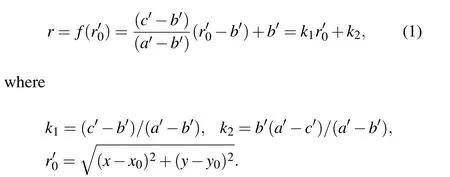
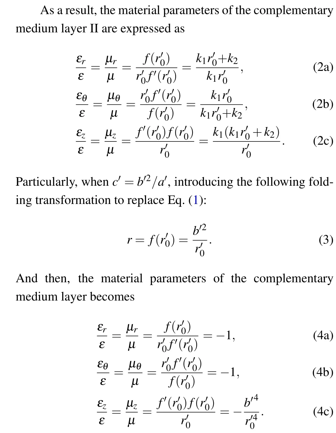
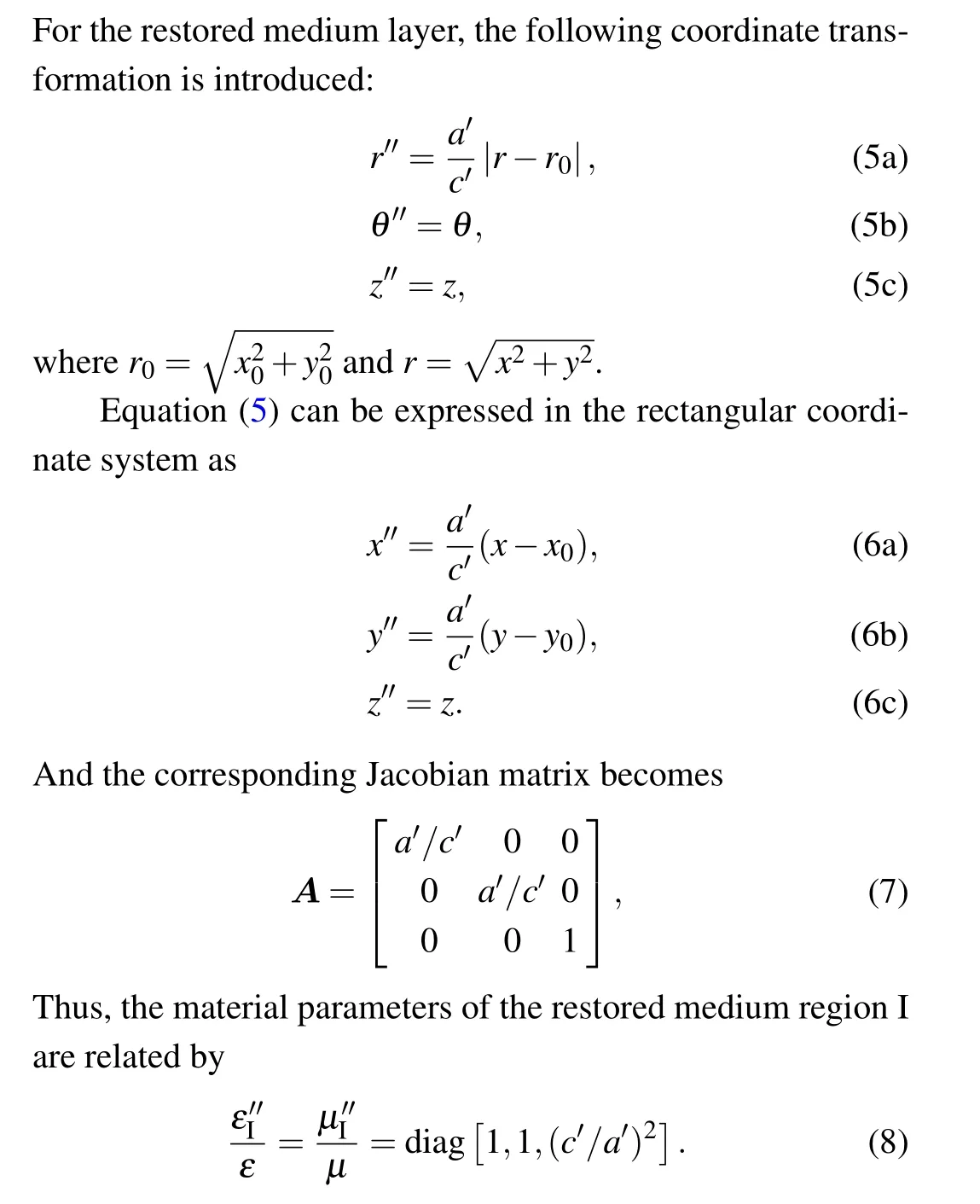
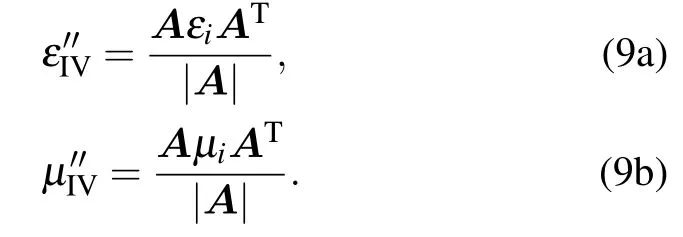
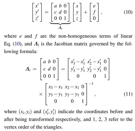
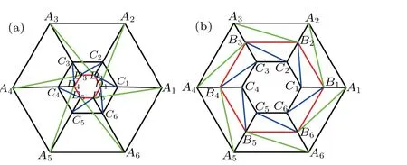
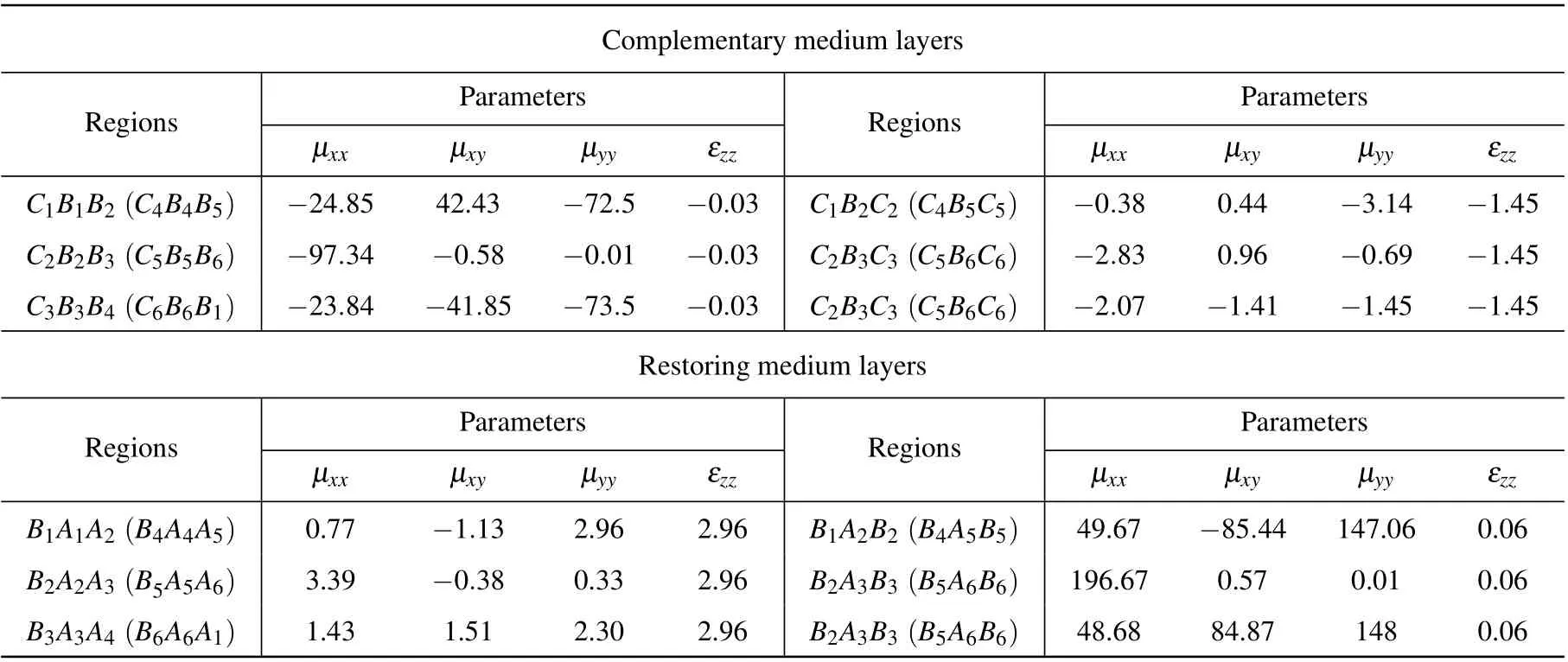
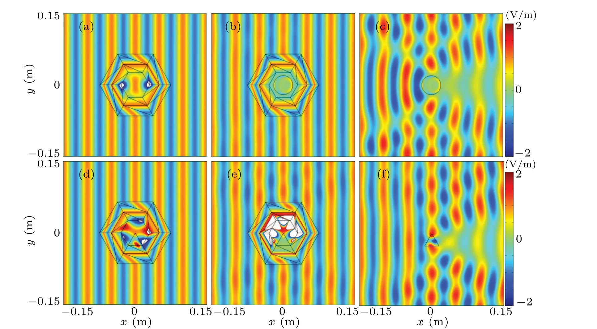
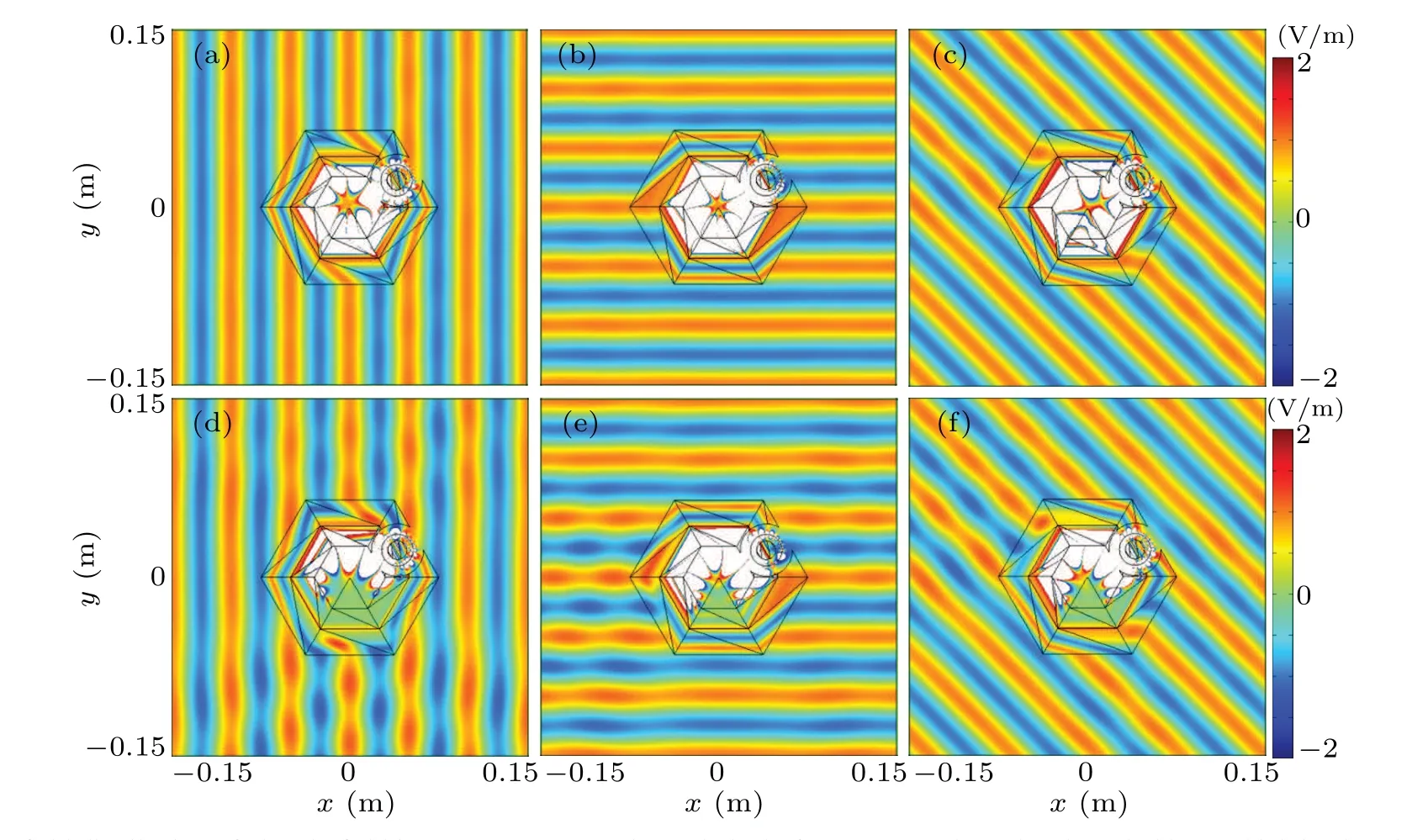
The key to the method of designing the reusable interactive stealth phantom device is the equivalent component as shown in Fig. 1. According to the idea of folding geometric transformation and complementary media,the outermost ring layer (b Fig. 1. Schematic diagram of equivalent component, showing (a) folding transformation process, (b) equivalent components, and (c) objects that are visually equivalent to equivalent component in panel(b). According to the above-mentioned equivalent transformation method, a reusable invisibility and phantom devices can be achieved by embedding an equivalent component in the boundary layer of a reciprocal cloak as shown in Fig.2,where the region in the dotted-line-sided box in Fig.2(a) can be replaced by the equivalent component shown in Fig. 2(b), and figure 2(c) shows the enlarged display of equivalent components in Fig. 2(b). It can be observed that a circular opening channel is formed around the equivalent component in Fig. 2(b), which can be used to change the object inside the phantom device and control it remotely. In order to calculate the material parameters of each area of the equivalent component, the center of the component shown in Fig.2(c)is assumed to be located at(x0,y0),and the outer radius of the invisible channel III, the complementary medium layer II, and the restored medium layers I and IV arec′,b′, anda′respectively.According to transformation optics,the material parameters of the complementary medium layer II can be obtained by folding the regionb′ Fig. 2. Schematic diagram of reusable reciprocal invisibility and phantom device design for (a) ideal reciprocal invisibility and phantom device, (b)open-structure invisibility and phantom device containing equivalent component,and(c)enlarged display of equivalent component. For the complementary medium layer shown in Fig.2(c),the following folding transformation is introduced:Since the restored medium region IV is derived from the space transformation of material parameters ofεiandμi, according to transformation optics, the material parameters of the restored medium region IV are Therefore,once the material parameters of the reciprocal invisibility and phantom device are known, an open structure can be designed according to the above mentioned method and the material parameters of equivalent components can be calculated from Eqs.(4),(8),and(9). And then,a reusable reciprocal stealth and phantom device is realized. It should be noted that when a linear transformation method is used to design the device, the material parameters of the reusable reciprocal stealth and phantom device become homogeneous, including the complementary medium and the restore medium. Taking 2D transformation for example and introducing the following linear transformation: According to transformation optics, the relationship among the material parameters in the regions before and after being transformed are expressed as Since the constitutive parameter of the transformation medium described in Eq.(12)is determined only by the Jacobian matrixΛi,which is only related to the coordinates of the mapped triangle vertices,the obtained constitutive parameters must be a homogenized tensor. The reciprocal invisibility and phantom device designed in this work has the characteristics of homogenization mentioned above. The COMSOL software will be used to simulate and verify its performance, and the detailed discussion will be shown in the following section. Figure 3 shows a schematic diagram of the space transformation of the reciprocal invisibility device with closedstructure,in which the circumradius of each polygon withAi,Bi,Ci, andDias vertices isa,b,c, andd, respectively. The design principle of reciprocal invisibility cloak device with closed-structure is to fold the regiond Fig.3. Schematic diagram of spatial transformation of homogenized reciprocal invisibility cloak with closed-structure,showing(a)virtual space and(b)physical space. Firstly,the circumradius of each polygon withAi,Bi,Ci,andDias vertices isa=0.075 m,b=0.05 m,c=0.03 m,andd=0.001 m respectively, and the frequency of the incident TE electromagnetic wave is set to be 6 GHz. As a result, the calculation results of the material parameters of each region in the physical space are listed in Table 1. Table 1. Material parameters of physical space. Figure 4 shows the electric field distribution of the reciprocal invisibility cloak device with the regular hexagonal polygon closed-structure, in which the core area of the cloak shown in Fig.4(a)is a free space,and the cylindrical boundary inside the cloak shown in Fig.4(b)is set to be the PEC boundary. For comparison, figure 4(c) shows that a cylinder with PEC boundary is placed independently in the free space. The material parameters of each triangle are shown in Table1. It can be seen that the electric field can penetrate into the reciprocal cloak,and the wavefront is perfectly restored in the front of the proposed cloak without scattering no matter whether the target object is placed inside the cloak. However, significant field scattering phenomenon can be observed when the target object is directly located in the free space. This indicates that the closed and reciprocal cloak has the ability to hide the target object as well as to sense the external signals,which is consistent with the cloaks described in the early literature.[34–37] Fig.4. Electric field distribution around(a)ideal cloak,[(b)and(c)]PEC cylinder with radius of 0.02 m,placed in the cloak or free space,[(d)and(e)]triangular object placed in cloak filled with or without“anti-object”,and(f)purely triangular object in free space. Next, the cylindrical object is replaced with a triangular-shaped object whose material parameters areε0=6.25+0.01j (the imaginary part represents the material loss)andμ0=1,and the“anti-object”is filled in the corresponding complementary medium region,i.e.,the permittivity values of the trianglesB5A5A6andC5B6C6are set to be?0.03?(6.25+0.01j)and?1.45?(6.25+0.01j),respectively,while keeping the permeability unchanged. The near electric filed distribution is shown in Fig. 4(d). As can be seen, the triangularshaped object becomes invisible,and the electric field can radiate to the object,i.e., the target object has the capability of simplex communication,which is no different from the traditional interactive invisibility device such as the external cloak in performance. In order to investigate the characteristics of the reciprocal stealth device, the triangular-shaped object in Fig.4(d)is kept while g the“anti-object”is removed from the complementary medium area,i.e., both the permittivity and permeability of the triangleB5A5A6andC5B6C6are fixed as shown in Table 1. In such a situation, the near-electric field distribution is simulated as shown in Fig. 4(e). Figure 4(f)represents the electric field distribution when the triangularshaped object is directly placed in the free space. From Figs. 4(d)–4(f), it can be observed that when the triangularshaped object is directly placed in the free space, the scattering phenomenon of the electric field can be observed obviously. However, once the object is enclosed by the proposed reciprocal cloak,the scattering phenomenon nearly disappears whether the “anti-object” exists or not. Such a result shows that the invisibility capability of reciprocal stealth device with closed-structure is independent of the geometric structure nor material properties of the target object,which is the difference between the cloak designed here and the traditional interactive cloak in the early literature,[34–37]and also reflects the superiority of the cloak designed here. It should be emphasized that the size of the cloak can be enlarged if need be, but the material parameters will also change accordingly.However,in practice,owing to the use of lossy metamaterials technology to synthesize devices,factors such as the size of the metamaterial and the operating frequency of the cloak must be fully considered to satisfy the condition that the size of the metamaterial is much smaller than the wavelength.No further technical proofs are made here for brevity. Figure 5 describes the far-field distribution of the electric field for the target object with or without the proposed reciprocal cloak. Figure 5(a) shows the far-field mode of Figs.4(b)and 4(c),and figure 5(b)displays the far-field mode of Figs. 4(e) and 4(f). It can be observed that the far-field amplitude of the object enclosed by the cloak is well suppressed compared with the far-field amplitude of the object in the free space. The far-field amplitude drops below?24 dB and?17 dB in Figs. 5(a) and 5(b) respectively. The simulation results fully confirm the prominent stealth effect of the proposed reciprocal device. Fig. 5. Comparison between (a) far-field mode distributions of Figs. 4(b)and 4(c),and between(b)far-field mode distributions of Figs.4(e)and 4(f). Figures 6(a)–6(c) demonstrate the electric field distributions when a triangular-shaped object with material parameter ofε0=6.25+0.01j andμ0=1 is placed at the bottom part inside the device and its corresponding “anti-object” is set in the complementary medium regions(i.e.,the material parameters are identical with those of Fig. 4(d)). As can be seen,no matter what the incident direction of the TE plane wave is,the open-structure reciprocal cloak has a good stealth effect.In order to study the uniqueness of the proposed device, the“anti-object”corresponding to the triangular-shaped object is removed from the complementary medium (i.e., the material parameters are identical with those of Fig. 4(e)) as shown in Figs.6(d)–6(f). It can also be found that the open-structure reciprocal cloak without“anti-object”has a good stealth effect.Comparing with the case where the“anti-object”is filled,the electric field around the device jitters slightly when no “antiobject” exists, but it does not affect the stealthy performance of the device. In addition,it should be noted that this jitter can be eliminated by further refining the calculated grids. Fig. 6. Near-field distribution of electric field in open-structure reciprocal cloak, for [(a)–(c)] triangular-shaped object, which is placed at the bottom of the inner space of the device, and an “anti-object”, which is filled in the complementary medium region of corresponding part of the cloak; for[(d)–(e)]triangular object,which is placed at the bottom of the inner side of the device,and the anti-object,which is removed from the corresponding complementary media layer of the cloak. The incident directions of TE plane waves are along [(a) and (d)] the X axis, [(b) and (e)] the Y axis, and oblique incident[(c)and(f)]at different angles. The existence of the open channel makes the internal object able to be replaced easily at will,which has significant application value in reality,especially in the 3D scenes. Because in a 3D case,the target object is often enclosed by the device,and the replacement of it needs to destroy the wrapped layer of the device,which is not conducive to the device reusability.However,the function of reusability can be obtained when the device has such an open channel. To sum up, the application of open channel in the design of reciprocal stealth device not only solves the problem of simplex communication between the target object and the outside world, but also provides a reusable way of the device, which is beneficial to saving the manufacturing cost of device. Finally, the illusionary feature of the reusable reciprocal cloaking device is discussed. Figure 7(a) describes the near-(electric)field distribution of a triangular-shaped dielectric object with material parameters ofε0=6.25+0.01j andμ0=1,and the object is placed horizontally in the free space.It should be noted that the outermost layer of the reciprocal cloak is a restored medium. According to the equivalent transformation method described in Section 2,once the material parameter of the restored medium is multiplied byε0andμ0,another large equivalent object with material parameter ofε0andμ0will be appear in the virtual space. With this mechanism, the reciprocal cloak can be turned into an illusion device as shown in Fig.7(b),where the triangular object in Fig.7(a)is placed inside the open-structure reciprocal cloak also, but the restored medium of the outermost top part of the cloak are multiplied byε0=6.25+0.01j andμ0=1,i.e.,the permittivity of the trianglesC2B3C3andB2A3B3are set to be 2.96?(6.25+0.01j)and 0.06?(6.25+0.01j)while the permeability unchanged is kept. Since the reciprocal cloak does not need the anti-object,the permittivity and permeability of the triangleB5A5A6andC5B6C6are fixed as the forth line shown in Table 1.The equivalent object with material parameters ofε0=6.25+0.01j andμ0=1 is placed in the free space whose near-field distribution is shown in Fig.7(c). It can be observed that the electric field distributions in Figs.7(b)and 7(c)are identical,but they differ greatly from those in Fig.7(a). This means that the small horizontal triangle originally placed inside the interactive cloak is visually consistent with a large inverted triangle,i.e., the small triangular object is mapped into another large triangular object,and the object position is changed. Similarly,the existence of the open aisle makes it particularly easy to replace the target objects,which means that the device is reusable. Next,the far-field distributions of the electric field corresponding to Figs.7(a)–7(c)are calculated to quantitatively describe the illusionary function of the reusable interactive cloak as shown in Fig. 8. It can be seen that the far-field amplitude curves of Figs.7(b)and 7(c)are almost identical,and the maximum far-field amplitude is about 1.6 V/m, and both of them are obviously different from that of Fig.7(a). This fully demonstrates the good phantom functionality of the proposed reusable reciprocal cloak. Fig.7. Illusionary effect of reusable reciprocal cloak,indicating(a)electric field distribution of a triangular-shaped object in the free space,(b)electric field distribution of the triangular-shape object covered by the proposed reusable reciprocal cloak, and (c) electric field distribution of the equivalent object. In this work,based on the multi-folded transformation optics, reusable and reciprocal invisibility phantom device with homogeneous material parameters is proposed and designed.Unlike the results in previous literature, the target object to be invisible, enclosed by the proposed device, does not need using the corresponding anti-object to some extent,which removes the strict position and size dependence of object. Furthermore,by reasonably setting the parameters in the restored medium of the device,the phantom of the target object can be realized, which could be used to confuse the external detection equipment if need be. Finally,an open aisle is generated on the boundary of the closed layer of the device by introducing the equivalent component,which not only strengthens the simplex communication capability of the device,but also facilitates the replacement and remote control of the target object,so as to achieve the reusable function of the device. This helps achieve cost savings, resource reusing and intelligently controlling. It is believed that the reusable interactive invisibility phantom device presented here has the potential applications in the field of national defense and military engineering. Acknowledgements Project supported by the Natural Science Doctoral Research Start-Up Fund of Yunnan Normal University, China(Grant No.01000205020503130)and the Key Project of Applied Basic Research Program of Yunnan Province, China(Grant No.2018FA033).


3. Results and discussion
3.1. Reciprocal invisibility cloak with closed-structure

3.2. Reusable reciprocal invisibility cloak and its performance
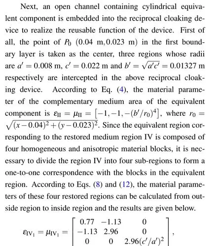
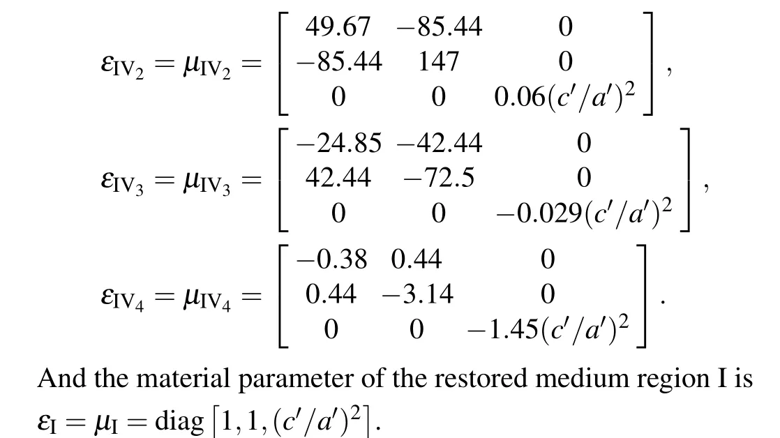
3.3. Illusion feature of reusable reciprocal cloaking device

4. Conclusions

