Spin splitting of vortex beams on the surface of natural biaxial hyperbolic materials
Hong Liang(梁紅), Haoyuan Song(宋浩元), Yubo Li(李宇博),Di Yu(于迪), and Shufang Fu(付淑芳),?
1Department of Physics,Harbin University,Harbin 150086,China
2Key Laboratory for Photonic and Electronic Bandgap Materials,Ministry of Education,School of Physics and Electronic Engineering,Harbin Normal University,Harbin 150025,China
Keywords: spin splitting,hyperbolic material,vortex beam,orbital angular momentum
1.Introduction
A polarization-dependent spatial shift in both in-and outof-plane directions is generated when linearly polarized light combining a left-handed circularly polarized (LCP) component and a right-handed circularly polarized (RCP) component refracts or reflects at a dielectric interface; this was defined as the spin Hall effect (SHE) of light by Onodaet al.in 2004.[1]In 2006,Bliokhet al.interpreted this concept and proposed that the conservation of total angular momentum is necessary.[2]It is well known that photons with two different spins in linearly polarized light carry different spin angular momenta.Generation of the SHE can compensate the extrinsic orbital angular momentum of different spin states to guarantee the conservation of angular momentum after reflection and refraction at the surface of materials.The SHE has attracted much attention and been applied in the development of new nanophotonic devices, such as plasmonics,[3,4]hyperbolic metamaterials (MMs),[5]topological insulators,[6]graphene,[7,8]black phosphorus,[9]and so on.
Recently, a variety of spatially structured beams with novel properties,such as vortex beams,[10]Airy beams[11]and Bessel beams,[12]have emerged, which provide a new path for studying the tunable SHE.A vortex beam with a continuous spiral phase and a vortex center phase singularity carries the orbital angular momentum and phase singularity.[13]Due to the consideration of orbital angular momentum,vortex beams have been widely used in optical communication,[14]trapping[15]and optical microscopy.[16]The spatial shifts of LCP and RCP components could be significantly enhanced with increase in the topological charge, which leads to the opportunity to observe the shifts directly.[17-19]Normally,the spin splitting produced by linearly polarized light is symmetric,i.e.,the position and intensity of the shifts of RCP and LCP components are equally separated.However, the asymmetry of spin splitting is also an interesting phenomenon, showing the powerful ability for multi-dimensional and flexible control of spin photons.[20]A vortex beam can be used to excite asymmetric spin splitting and has been widely studied in various systems such as graphene metamaterials,[17]an air-gold interface,[18]PT-symmetric metamaterials,[19]etc.
Hyperbolic metamaterials (HMMs), a class of artificial electromagnetic metamaterials, have been widely used in many fields due to their strong anisotropy and hyperbolic dispersion, for example in super-resolution imaging,[21,22]negative refraction,[23]optical waveguides[24,25]and ultra-sensitive optical sensing.[26]In contrast to HMMs, natural hyperbolic materials (NHMs), represented by hexagonal boron nitride(hBN) and alpha-phase molybdenum trioxide (α-MoO3), exhibit lower optical losses and are easy to prepare and highly stable.[27]In recent years,due to its in-plane anisotropy characteristics and excellent energy storage performance,α-MoO3has received widespread attention.[28-30]Compared with other hyperbolic materials,α-MoO3has two main advantages: one is that the hyperbolic frequency interval ofα-MoO3is wider.For example,for thec-axis([001]crystal direction)the hyperbolic frequency interval ofα-MoO3is three times that of hBN,which will be beneficial for broadband modulation of electromagnetic waves.[31,32]The other one is thatα-MoO3has three different hyperbolic frequency bands (RBs), and each RB corresponds to a different crystal axis,making it possible to achieve a hyperbolic surface in the plane.[31,32]Recently,Wanget al.studied the spin splitting of vortex beams irradiated on semi-infinite uniaxial natural hBN.[33]It was found that the spin splitting is significant when the Brewster angle or critical angle is satisfied, and the spin splitting can be enhanced by intrinsic orbital angular momentum.In contrast to hBN,the anisotropy ofα-MoO3films is stronger,which is attributed to their biaxial hyperbolic character.Meanwhile, the RBs ofα-MoO3are continuous from 545 cm-1to 1004 cm-1and overlap at the adjacent regions, which are wider than the separated ones of hBN.On the other hand,a rotation angle between the crystal direction ofα-MoO3and the incident plane is set,which will result in obvious asymmetry of spin splitting between LCP and RCP components.However, for the spin splitting of hBN,a pronounced asymmetry will emerge when the polarization angleα/=0?and 90?.
In this work, we focus on the SHE of a reflected vortex beam on the surface ofα-MoO3rotated by an angle with respect to the incident plane for differently polarized beams.The enhanced shifts can be realized by adjusting the corresponding physical parameters, such as the topological charge, and apparent asymmetry of spin splitting is observed.The organization of this article is as follows.In Section 2,the analytical expressions for in- or out-of-plane spatial shifts are derived.The spin splitting between LCP and RCP components is defined.The analysis corresponding to the spin splitting and the spatial shifts of LCP and RCP components under the effect of orientation angle,incident angle and the thickness ofα-MoO3,as well as the topological charge, is given Section 3.Finally,Section 4 summarizes the useful conclusions of this paper.
2.Theoretical description
The coordinate system and schematic diagram are shown in Fig.1(a).The principal axis coordinate system [a,b,c]represents the [100], [010] and [001] crystal directions, respectively,ofα-MoO3with thicknessd.Thea-andc-axes ofα-MoO3are in thex-yplane of the experimental coordinate system.Thea-axis is rotated by an angle?relative to thexaxis,which also represents the direction of the incident plane.A vortex beam is incident on the surface at an angleθin thex-zplane.The reflected beam splits along thex- andy-axes and produces the in- and out-of-plane spin splittings, respectively.Figure 1(b) represents the real parts of theα-MoO3permittivity, where the RBs are shown between epsilon-nearzero(ENZ)and epsilon-near-pole(ENP).In the principal axis coordinate system,the permittivity ofα-MoO3can be written as a diagonal matrix[εx,εy,εz].The components of permittivity can be collectively expressed by[35]
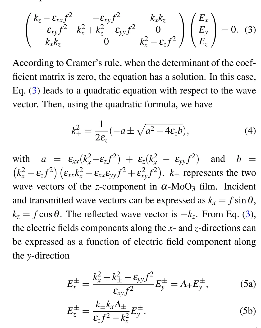
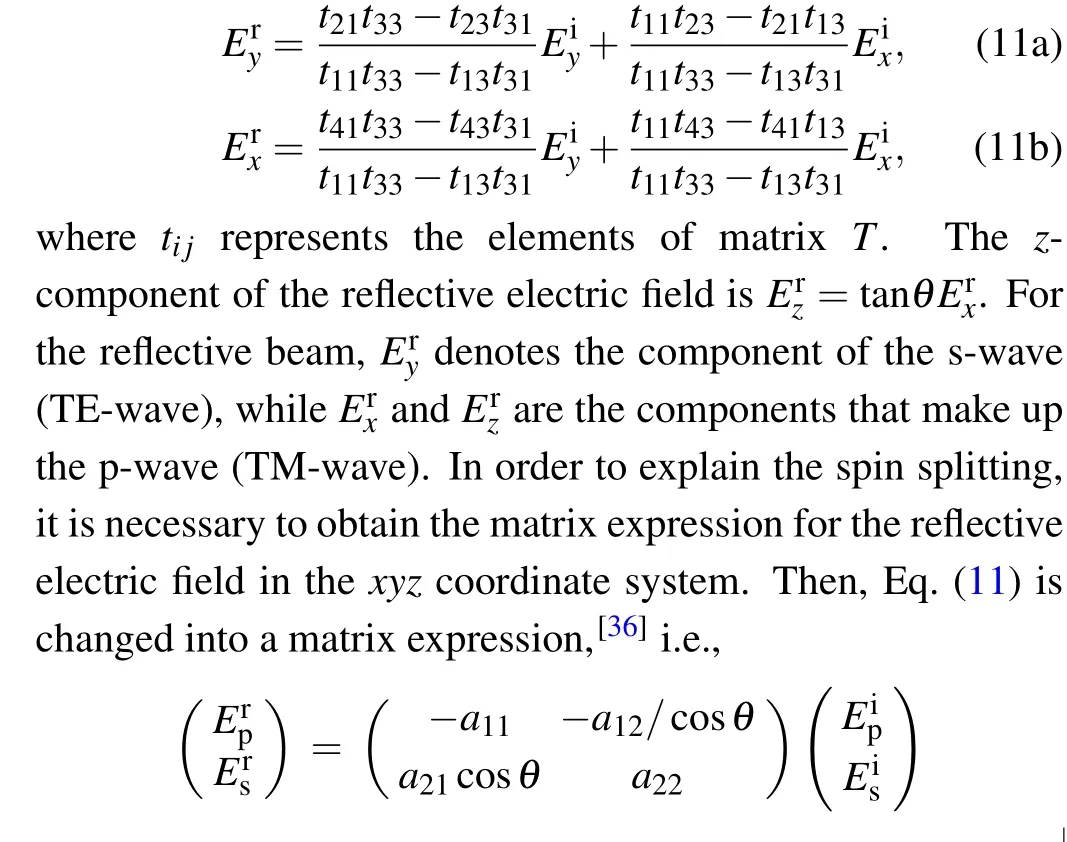
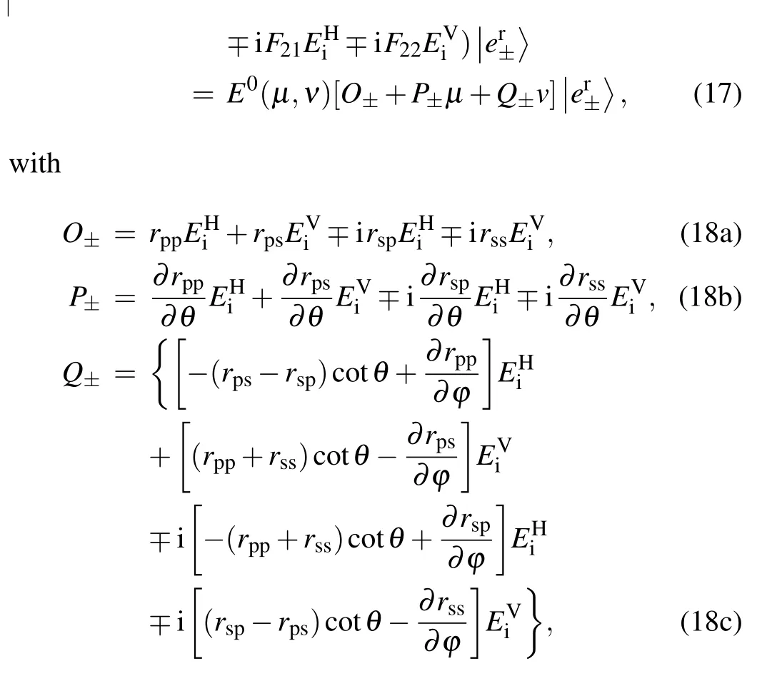
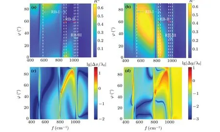
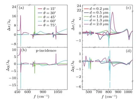
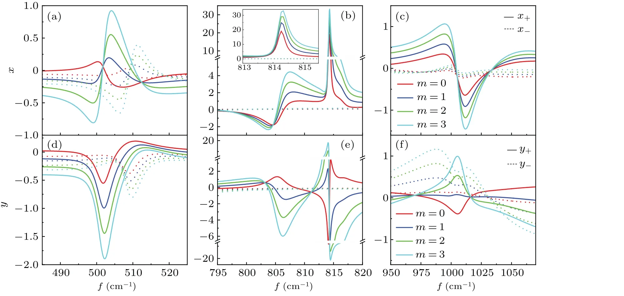
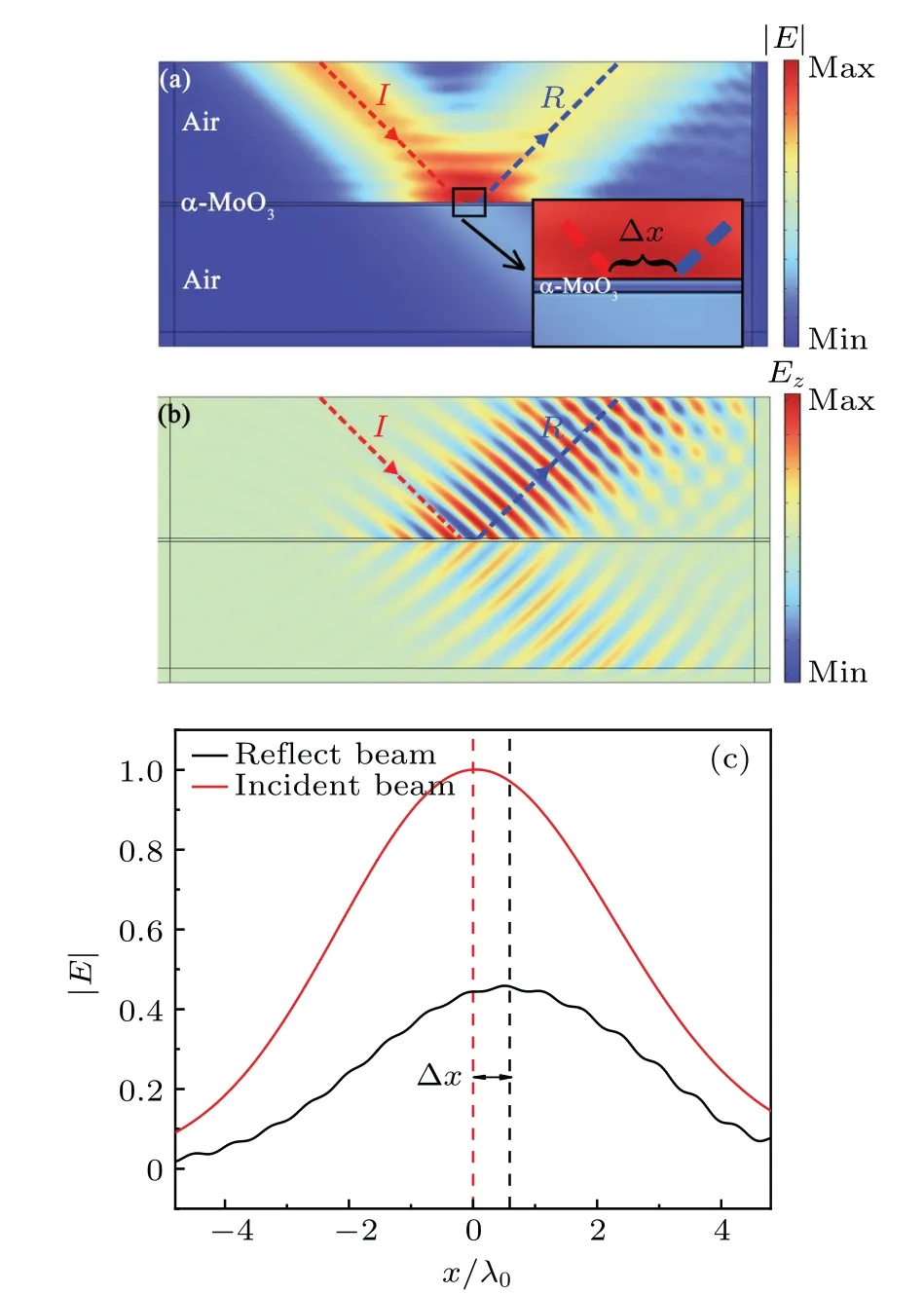
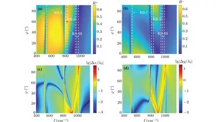
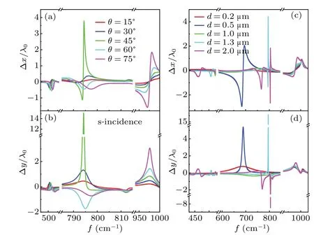
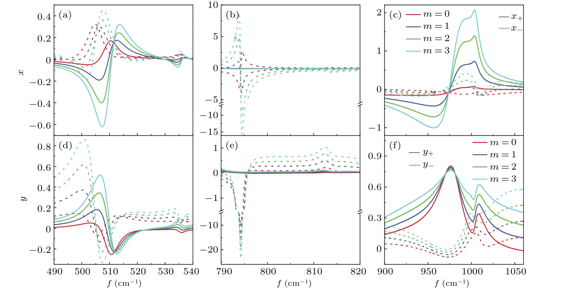
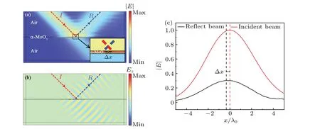
whereε∞is the high-frequency dielectric constant,fTOandfLOindicate the transverse and longitudinal optical phonon frequencies andτjis the phonon-damping constant.In Eq.(1),the frequency is generally measured in cm-1so thatfactually representsω/(2πc).The regions with negative values of permittivity along all three directions correspond to the hyperbolic frequency range.The frequency region 545 cm-1 Fig.1.The left graph illustrates the spin splitting of a reflected vortex beam from the surface of an α-MoO3 film with thickness d.The incident plane is the x-z plane.The red and blue rotating arrows represent the reflected LCP and RCP components,respectively.[a,b,c]represents the principal axis coordinate system and is rotated by ? with respect to the incident plane.The right graph illustrates the real parts of permittivity of α-MoO3. Since an angle?is set between thea-axis and thex-axis,a coordinate transformation is required.The equivalent matrix of permittivity can be written as[36] whereεxx=εxcos2?+εysin2?,εyy=εycos2?+εxsin2?,εzz=εzandεxy=(εy-εx)cos?sin?.With the Maxwell equation,three components of electric fields satisfy the following relationship: Hence, we propose only they-component of electric field in theα-MoO3film, but thex- andy-components in the other spaces as follows: In different spaces, the magnetic fields can be obtained fromH=?×E/(iμ0ω).Then, at the upper surface of theα-MoO3film, the electromagnetic boundary conditions can be written as whereλ±=k±k0εzΛ±/(εz f2-k2x).At the lower interface between theα-MoO3film and the air,we find whereγ±=k±fεzΛ±/(εz f2-k2x).For convenience,we transform Eqs.(7)and(8)into matrix forms as follows: wherep±±= exp(±ik±d).Combining the two matrices of Eqs.(9a) and (9b), we eliminate the electric field amplitudesA,B,CandDto obtain the relationship between incident,reflected and transmitted electric fields whereT=T1T-12.According to Eq.(10),the relationship between incident and reflected fields can be obtained as with The incident beam, as a near-axial beam, has a narrow plane wave distribution along the center wave in momentum space.Ifμandνindicate the in-plane and out-of-plane deflections of non-central wave vectors,respectively,the reflective electric field components can be rewritten with the angular spectrum theory for the ordinary situation[36,37] where the terms related toμdenote the in-plane momentum gradient of the Fresnel coefficients and the terms related toνdenote the geometric spin-orbit terms. For convenience,we use a simple vortex beam as the incident beam to simulate the spin-splitting.The simple vortex beam is equal to the first-order Laguerre-Gaussian beam whose radial index is equal to zero and its envelope does not depend on the radial coordinate at all.The angular distribution of electric field is explicitly expressed by[33,36] wheremis the azimuthal quantum number characterizing the optical vortex and its sign indicates the direction of the vortex.w0is the width of the beam waist andk0is the vacuum wave number.The field amplitude components corresponding to any branch wave in the reflected beam can be expressed as whereFijrepresents the elements of matrixF,O±represents the terms regardless ofμandν,P±only includesμand omitsνandQ±only includesνand omitsμ.Therefore,the spatial shifts of either spin-state component can be defined as[36]Heree1±=|O±|2,e2±=O?±P±+P?±O±,e3±=O?±Q±+Q?±O±,e4±=|P±|2,e5±=|Q±|2,f1±=O?±P±, andf2±=O?±Q±.?xy=〈x+,y+〉-〈x-,y-〉is the shift difference between LCP and RCP components, i.e., the spin splitting.[30]Whene1±?(m+1)(e4±+e5±)/(k2w20), the second term of the numerator in Eqs.(20a) and (20b) represents the primordial shifts which are caused by the Gaussian beams.The first term represents the dependence on the intrinsic orbit angular momentum, which results in the linear increase of the spatial shifts with increase in the azimuthal quantum number.Ife1± ?(m+1)(e4±+e5±)/(k2w20), the beam shifts tend to zero due to|O±|?|P±| and|O±|?|Q±|.Whene1±is of the same order of magnitude as (m+1)(e4±+e5±)/(k2w20),the effect of the topological charge number on the spin splitting becomes more complex.If we replaceα-MoO3with an isotropic medium,the effect of orientation angle?on the permittivity matrix will disappear,which causes the reflection coefficientrps=rsp=0.In this case,Eq.(17)can be transformed as Substituting Eq.(22)into Eq.(20),the spatial shifts of p-and s-incidences can be achieved, which will be reduced to the well-known result shown in Ref.[33]. The relevant physical parameters forα-MoO3film are as follows: along thexdirection ([100] crystal direction),ε∞=4.0,fLO=972 cm-1,fTO=822 cm-1andτx=4 cm-1;along theydirection([001]crystal direction),ε∞=5.2,fLO=851 cm-1,fTO=545 cm-1andτy=4 cm-1; along thezdirection([010]crystal direction),ε∞=2.4,fLO=1004 cm-1,fTO=958 cm-1andτz=2 cm-1.The thickness of theα-MoO3film is fixed atd=1.3μm.Two typical linearly polarized vortex beams are considered to investigate the spin splitting between LCP and RCP components. The reflection spectra for LCP and RCP components with varying orientation angle and frequency are illustrated in Figs.2(a)and 2(b),where we selectw0=40λ0,θ=45?andm=1.From the color bar,it can be seen that the yellow region in the reflection spectra represents higher reflection,while the blue region corresponds to relatively lower reflection.The differences in the reflection spectra are evident for different spin components,where an asymmetric phenomenon is observed in RBs.As shown in Fig.2(b),the reflection of the RCP component exceeding 50%can be achieved in the range of?>20?for RB-I and?<40?for RB-II.However,the reflection of the LCP component in Fig.2(a)is very small and even approaches zero in the region of?>40?in RB-II.It is well known that a larger spatial shift generally corresponds to a smaller reflectivity, especially where the reflection is close to zero.In this way,it is possible that this apparent asymmetry of reflectance will lead to a different distribution of the spin splitting with the frequency.Figures 2(c)and 2(d)present the spin splitting for the LCP or RCP component versus the orientation angle and frequency, where the maximum and minimum distribution of spin splitting are obviously related to the reflectance.From the color bar,the red region relates to a larger spin splitting,while the blue region indicates that the spin splitting is small or even tends to zero.In the spin-splitting spectra, the dark blue line indicates that the spin splitting is equal to zero, which means that the spatial shift of LCP and RCP components may be displaced in the same direction and with the same magnitude.The dark red line shows the maximum of the spin splitting due to the spatial shift of LCP and RCP components along the different directions.For example,the in-plane spin splitting can reach 25λ0,while out-of-plane spin splitting can be 10λ0.As is evident from a comparison with Figs.2(a)and 2(b),the maximum value of spatial shift is produced by the LCP component and the minimum value is due to the RCP component. Next, we simulated the curve of spin splitting as a function of frequency under different incident angles, as shown in Figs.3(a) and 3(b).Based on Figs.2(c) and 2(d), we set?= 45?, where the maximum of spin splitting can be observed.For in-plane spin splitting, shown in Fig.3(a), three peaks can be found, located near ENP of RBI and RBII, as well as ENZ of RBIII.The maximum of the spin splitting,about ?xmax/λ0≈25 occurs near ENP of RBII atθ= 45?.A transition between positive and negative spin splitting is achieved at the first peak,with only needing to change the incident angle from 75?to 60?.In addition, the spin splitting is very small whenθ<45?.For out-of-plane spin splitting,a negative maximum of about ?y/λ0≈-16.5 is obtained atθ=60?and ENP of RB-I,where a positive maximum of about?y/λ0≈8.9 can be observed if the incident angle is set to 75?.The relatively larger spin splitting also can be generated in the other two RBs.With decreasing incident angle,the spin splitting will quickly tend to be zero,especially forθ<30?.Two cases may cause the spin splitting to be zero.One is when the shifts of both the LCP and RCP components are very small and the other is when the shifts of the LCP and RCP components have the same amplitude and direction although larger shifts are produced.Therefore,if we focus on the polarization of the reflected beam,we have to control the incident angle to be larger than 30?.Of course, if we only hope for large spatial shifts regardless of the polarization of the reflected beam a smaller incident angle should be also considered.Figures 3(c)and 3(d) present the spin splitting as a function of frequency for different thicknesses ofα-MoO3at?=θ=45?.Obvious spin splitting also occurs in or near the RBs, particularly in RB-II near ENP; the maximum of the in-plane spin splitting, about 20λ0, is observed atd=1.3 μm, and also about-6.5λ0for the out-of-plane spin splitting.In or near RB-I,the spin splitting will move to the lower frequency with increasing thickness; however, in RB-III, the spin splitting will be independent on the thickness ofα-MoO3.From Eq.(10b),a zero reflection will be obtained ifk±d=nπ,leading to significant spin splitting.- Fig.2.Reflection of LCP and RCP components in(a)and(b),respectively,versus frequency and orientation angle at θ =45?for p-incidence.The yellow region represents higher reflection while the blue region corresponds to relatively lower reflection.The corresponding in-plane and out-of-plane spin splittings are presented in(c)and(d),respectively.To better illustrate the trends,we have utilized a logarithmic coordinate system.The red region is related to a larger spin splitting,while the blue region indicates a small spin splitting close to zero. Fig.3.(a), (b)In-plane and out-of-plane spin splitting for various incident angles at ?=45?,respectively.(c),(d)In-plane and out-of-plane spin splitting for various thickness of α-MoO3 θ =? =45?,respectively. In order to more intuitively illustrate the possible relationship between the spatial shifts and the spin splitting produced by LCP and RCP components, Fig.4 shows the variation of the spatial shifts with frequency under different topological charges.The orientation and incident angles are fixed at?=θ=45?since the maximum of spin splitting can be achieved, as shown in Figs.2 and 3.When a Gaussian beam is incident on the surface ofα-MoO3,namely,m=0,the spatial shifts of LCP and RCP components are also presented.In-plane spatial shifts only can be excited by the LCP components,but the spatial shifts of the RCP components are almost zero.In addition,the spatial shifts generated by the LCP components are located in the three RBs; in particular, the maximum magnitude aboutx+max/λ0≈33 atm=3 lies in RB-II,as shown in Fig.4(b).The inset in Fig.4(b) further shows that the spatial shifts will increase with increase in topological charge.We can conclude that the spin splitting also will increase with topological charge.The spatial shifts of LCP and RCP components exhibit apparent asymmetry.In this way,we can choose different reflected polarized beams according to the requirements of practical applications.For example, if a zero or tiny spatial shift is anticipated, the RCP component can be selected.However, if a large spatial shift is needed we can consider the LCP component.The out-of-plane spatial shifts in RB-II(see Fig.4(e))are complicated and sensitive to the frequency.Whenm=0,the spatial shifts of the LCP component present two positive peaks and one negative dip.But as the topological charge increases, one of the positive peaks jumps to the negative one.The positive and negative maxima abouty+max/λ0≈±20 can be obtained atω=813 cm-1and 814 cm-1.Therefore,the direction of the spatial shifts can be adjusted by precisely controlling the incident frequency.In the other two RBs presented in Figs.4(d) and 4(f), the relatively small spatial shifts that can also be observed are produced by the RCP component.It is obvious that the maximum of spin splitting occurs at the maximum positive and negative spatial shifts, where the spatial shifts of the RCP component disappear. Fig.4.In-or out-of-plane spatial shifts of the reflected vortex beam for p-incidence under various topological charges at ? =θ =45?. Fig.5.(a) Electric-field distribution (simulated using the commercial software Comsol Multiphysics)of the p-incidence on the surface of an α-MoO3 film at f =814 cm-1.The other parameters are the same as those in Fig.4(b).(b)Distribution of z-components of incident, reflected and transmitted electric fields.(c) Comparison of |E| profiles between the center of the incident and reflected beams. The simulation results for in-plane spatial shifts using the commercial software Comsol Multiphysics atm=0 for p-incidence withf=814 cm-1are presented in Fig.5.The center of the reflected beam,marked by the black dotted line,moves obviously to the right along the interface between air and theα-MoO3film.In addition, the electric field intensity is significantly enhanced at the interface.According to Fig.4(b), it can be seen that the in-plane spatial shifts only result from the LCP component,which also can be further reflected through thez-component of electric field in Fig.5(b).A comparison of the|E| profile between the incident and reflected beams is made in Fig.5(c).The movement along thex-direction is approximatelyx/λ0≈0.8, which exactly satisfies the theoretical result shown in Fig.4(b). The reflective spectra versus frequency and orientation angle of two spin components for s-incidence are shown in Figs.6(a) and 6(b).Unlike the reflective spectra for pincidence, the reflection of the LCP component in RB-I and RB-II is obviously larger than that of the RCP component.The maximum of reflection, almost exceeding 50%, lies in the range 20?20?for RB-II, as shown in Fig.6(a).However, the reflection of the LCP component in RB-III achieves a minimum ofR+≈0 once?>20?;in addition,with increasing?the minimum of the reflection moves to a high frequency and approaches the right boundary of RB-III.For the reflection of the RCP component shown in Fig.6(b),the maximum appears near?=0?for RB-I and?=90?for RB-II.Similar to the reflective spectra for p-incidence, the reflected intensity exhibits an asymmetric property and varies with the orientation angle.Figures 6(c)and 6(d)present the spin-splitting spectra corresponding to the reflection of the LCP or RCP components,where the asymmetry of the reflectance will result in obvious zero or larger spin splitting.Compared with Figs.6(a)and 6(b),in or near RB-I and II it can be predicted that the zero spin splitting represented by dark blue lines should originate from the relatively small spatial shifts with the same direction,but the one in RBIII may result from large spatial shifts in the same direction.The dark red lines also represent the distribution of significant spin splitting,which mainly lies in RB-II and RB-III;in addition, at the boundary of these, the maximum of spin splitting can be easily obtained when?=0?or 90?. Fig.6.Reflection of LCP and RCP components in(a)and(b),respectively,versus frequency and the orientation angle at θ =45?for s-incidence.The yellow region corresponds to higher reflectance while the blue region corresponds to relatively lower reflectance,approaching zero.The corresponding in-plane and out-of-plane spin splittings are presented in(c)and(d),respectively.To better illustrate the trends,we have utilized a logarithmic coordinate system.The red region corresponds to a larger spin splitting,while the blue region corresponds to a spin splitting close to zero. Fig.7.(a), (b) In-plane and out-of-plane spin splitting for various incident angles at ? =45?,respectively.(c),(d)In-plane and out-of-plane spin splitting for various thicknesses of α-MoO3 at θ =? =45?,respectively. The effect of the incident angles for s-incidence on the spin splitting is investigated at?=45?in Figs.7(a)and 7(b).For in-plane spin splitting, as shown in Fig.7(a), three peaks are just consistent with the results in Figs.2(c)and 2(d).The spin splitting is smaller than that produced by p-incidence,where the positive maximum is about ?xmax/λ0≈3.8 atθ=45?andω=794 cm-1in RB-II.Another relatively large spin splitting of about ?xmax/λ0≈2.0 atθ=75?appears in RB-III.It can be seen that if?<45?,the spin splitting will be less thanλ0in all the RBs.For out-of-plane spin splitting, as shown in Fig.7(b), the positive maximum of spin splitting is about?ymax/λ0≈15 atθ=45?;obviously is larger than that shown in Fig.3(b).The negative maximum of spin splitting of about?ymax/λ0≈-2 can be achieved only by changing the incident angle to 60?,which is far from that generated by p-incidence.In RB-III, the spin splitting increases monotonically with increasing incident angle and reaches about 2.5λ0atθ=75?.Therefore, the magnitude and incident frequency of the spin splitting can be adjusted by the incident polarization.As an example,if the maximum of in-or out-of-plane spin splitting appears in RB-I, we have to choose p-incidence; however, if the maximum occurs in RB-II,s-incidence will be considered.Figures 7(c) and 7(d) show the dependence of the spin splitting on the thickness ofα-MoO3.With increasing thickness,the spin splitting in RB-I and RB-II near ENP increases to a maximum atd=1.3μm and then decreases again.However,in RB-III near ENZ,the produced spin splitting hardly changes with thickness.It can be found from Fig.1(b) that the wave vector changes rapidly due to the significant variation of permittivity near ENP, which results in the conditionk±d=nπbeing easily satisfied.On the other hand, the wave vector in the ENZ region changes more smoothly, which weakens the effect of thickness on spin splitting. Finally, the in- or out-of-plane spatial shifts of the LCP and RCP components at?=θ=45?are presented in Fig.8.Compared with Fig.4,the maximum in-and out-of-plane spatial shifts are mainly generated by RCP components in RB-II near ENZ(see Figs.8(b)and 8(e)).On the contrary, the corresponding spatial shifts of LCP components approach zero.The apparent spin splitting should appear due to the asymmetry of spatial shifts of RCP and LCP components.For an inplane spatial shift,positive and negative spatial shifts of about±10λ0are achieved atm=3 atω=794 cm-1and 795 cm-1.Form=0,a relatively large spatial shift can also be observed in RB-II.In the other two RBs presented in Figs.8(a)and 8(c),the spatial shifts are relatively smaller.In RB-I,the sign of the maximum spatial shifts excited by LCP and RCP components is opposite,and the magnitude of shifts is less thanλ0.However,in RB-III near ENZ,the positive maximum of about 2λ0can be achieved by the LCP component.For out-of-plane spatial shifts, the negative maximum of abouty-max/λ0≈-20 is observed atm=3 atω=794 cm-1and the positive one is aboutλ0atω=813 cm-1,as shown in Fig.8(e).In Figs.8(d)and 8(f), the spatial shifts are less thanλ0and the polarized components can be selected according to the requirement for the direction of the spatial shift. Fig.8.In-or out-of-plane spatial shifts of the reflected vortex beam for s-incidence under various topological charges at ? =θ =45?. Fig.9.(a)Electric-field distribution of the s-incidence on the surface of an α-MoO3 film at f =793 cm-1.The other parameters are the same as those in Fig.8(b).(b) Distribution of z-components of incident, reflected and transmitted magnetic fields.(c) Comparison of |E| profiles between the center of the incident and reflected beams. In order to further examine the in-plane spatial shift for sincidence,Fig.9 shows the electric field distribution atm=0 withf=793 cm-1.Figure 9(a)indicates that the center of the reflected beam moves slightly to the left across the null point along the interface between air and theα-MoO3film, which means that a negative spatial shift occurs.Thez-component distribution of the magnetic field is presented in Fig.9(b).Combined with Fig.8(b), it further demonstrates that the inplane spatial shifts come from the RCP component due to the zero shift of the LCP component.Finally,the movement of the|E| profile between the incident and reflected beams is aboutx/λ0≈-0.2, as shown in Fig.9(c), which agrees with the calculated value in Fig.8(b). In this work we investigated the spin splitting of reflected vortex beams on the surface of anα-MoO3film rotated by an angle?with respect to the incident plane.Two typical polarizations of vortex beams, namely p- and s-incidence, were considered for discussing the spin splitting of LCP and RCP components along thex- andy-directions.The analytical expression for the spatial shifts for the two spin components in the reflective beam was derived,with the spin splitting defined as the shift difference between the two spin components.The sign of the spin splitting indicates the relative positions of the spatial shifts in thexyzcoordinate system.We found that obvious spatial splitting normally occurs in the RBs ofα-MoO3crystal,particularly near ENZ or ENP.For p-incidence,the inor out-of-plane spin splitting mainly comes from the spatial shift of the LCP component since that of the RCP component approaches zero.However,for s-incidence,in-or out-of-plane spin splitting results from spatial shifts of the RCP component due to the zero shift of the LCP component.The orientation of the optical axis ofα-MoO3plays an important role in the appearance of the asymmetry.With increasing topological charge, the spatial shifts are greatly enhanced.The effect of the incident angle and the thickness ofα-MoO3on the spin splitting was also examined, and the optimum incident angle and thickness ofα-MoO3crystal were determined.The present work may provide a new way for modulating the beam shift and a possibility for developing new tunable anisotropic optoelectronic devices. Acknowledgement Project supported by the Natural Science Foundation of Heilongjiang Province of China(Grant No.LH2022F041).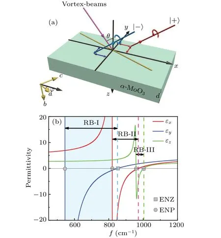


3.Numerical results and discussion
3.1.Spin-splitting for p-incidence
3.2.Spin-splitting for s-incidence
4.Summary
- Chinese Physics B的其它文章
- Diamond growth in a high temperature and high pressure Fe-Ni-C-Si system: Effect of synthesis pressure
- Si-Ge based vertical tunnel field-effect transistor of junction-less structure with improved sensitivity using dielectric modulation for biosensing applications
- Speeding-up direct implicit particle-in-cell simulations in bounded plasma by obtaining future electric field through explicitly propulsion of particles
- Temperature-induced logical resonance in the Hodgkin-Huxley neuron
- Energy-distributable waterborne acoustic launcher for directional sensing
- Structural stability and ion migration of Li2MnO3 cathode material under high pressures

