8-Weighted-Type Fractional Fourier Transform Based Three-Branch Transmission Method
Jing Li, Xuejun Sha*, Xiaojie Fang, Lin Mei
Communication Research Center, Harbin Institute of Technology, Harbin 150001, China
Abstract: To improve the bit error rate (BER)performance of multiple input multiple output (MIMO) systems with low complexity, a three-branch transmission scheme employing 8-weighted-type fractional Fourier transform (8-WFRFT) module is proposed. In the proposed scheme, the original signal is first decomposed into eight sub-signals and then merged into three component signals by the same carrier pattern. The three signals have mathematical constraint relations among themselves that can counteract the channel fading.They are simultaneously transmitted via three independent antennas after delay regulating.At the receiver, an inverse 8-WFRFT module is employed to obtain the estimated original signal by processing the received signal.Then, the bit error rate (BER) performance,transmitting power, transmission rate, power spectrum and computational complexity of the proposed scheme are analysed in detail. Numerical results show that the proposed scheme has a superior performance compared to STBC based three-antenna transmission scheme, in terms of BER performance.
Keywords: 8-weighted-type fractional Fourier transform (8-WFRFT); bit error rate (BER);low complexity; multiple input multiple output (MIMO)
I. INTRODUCTION
Nowadays, the wireless communication technologies are developing rapidly. The wireless businesses, such as digital broadcasting and communication network services [1,2], are expected to operate at high transmission quality and high data rate.
Multiple-input multiple-output (MIMO)technology shows promising capability in increasing spectrum efficiency and channel capacity by effectively utilizing spatial resources. It has been used in many aspects, such as antenna selection technology[3], optimal power allocation[4] and anti-interference coordinated transmission[5]. As a tradeoff algorithm between anti-fading ability and complexity of the receiver, the space time block coded(STBC) method is able to obtain the maximum diversity gain in MIMO systems [6,7].Whereas, the coding complexity of the STBC method grows with the increase of the number of antennas. Thus, the full diversity is dif ficult to be obtained.
4-Weighted-type fractional Fourier transform (4-WFRFT), a different form of the fractional Fourier transform (FRFT), is suitable for digital communication systems with low complexity [8]. In recent years, it has attracted extensively interest [9,10]. As a new time-frequency collaborated analysis scheme,4-WFRFT can depict time and frequency characteristics specifically [11]. In contrast,the conventional communication theories are dif ficult to give a brief description of the complicated time-frequency relation. The time-domain signal and frequency-domain signal can also be called single-carrier (SC) signal and multi-carrier (MC) signal, respectively. SC scheme and MC scheme are two basic carrier schemes in previous studies. 4-WFRFT based hybrid carrier (HC) scheme can inherit the properties of SC and MC schemes [12].It can be adjusted by the order of 4-WFRFT to achieve the coordinated transmission of SC system and MC system, Due to the strong anti-interference capability and energy distribution uniformity, HC system has been widely used for combating channel fading in complex scenarios. In [13], the performance of HC system with MMSE equalization over doubly-dispersive channels was investigated. A multiple parameters weighted fractional Fourier transform and constellation scrambling method based physical layer security system was proposed in [14]. The HC communication with Partial FFT demodulation over underwater acoustic channels was investigated in [15].
To obtain better bit error rate (BER) performance of MIMO systems with low complexity, 8-weighted-type fractional Fourier transform (8-WFRFT) is considered. It belongs to multifractional Fourier transform (M-WFRFT)which can be seen as a general form of 4-WFRFT [16]. The mathematical explanation of M-WFRFT is presented, but there are few applications in communication systems. The aim of this paper is to present a 8-WFRFT based multi-antenna transmission scheme to improve the BER performance of communication systems with low complexity. Meanwhile,the combination of M-WFRFT technology and existing communication systems can be implemented. The sub-signals of the 8-WFRFT signal contain SC signal, MC signal and HC signal. So, according to the channel state information, the suitable carrier form can be chosen to transmit for better system performance. In addition, by the combination of sub-signals, the signals can be transmitted via the arbitrary number antennas. The definition of 8-WFRFT and the system structure of the proposed scheme are elaborated. The transmitted signals, BER, transmitting power, transmission rate, power spectrum and the whole computational complexity are successively discussed. The simulation results demonstrate that the proposed scheme is superior to the STBC based transmission scheme, in terms of BER performance and transmission rate.
The rest of this paper is organized as follows. The mathematical preliminaries of 4-WFRFT and 8-WFRFT are reviewed in Section II. The system model and signal processing of 8-WFRFT based three-branch transmission method are given in Section III.Numerical results and discussions are revealed in Section IV. Finally, Section V contains the conclusions.
In this paper, an 8-W F R F T b a s e d multi-antenna transmission scheme is presented for better BER performance with low complexity in MIMO systems.
II. PRELIMINARY
2.1 4-Weighted-type fractional Fourier transform
4-WFRFT was pioneered by C. C. Shih in 1995 [7]. It can be regarded as the weighted superposition of the four different integer -order Fourier transforms with different weighting coefficients. The representation of the 4-WFRFT of discrete sequences was proposed in [11]. The definition of α-order 4-WFRFT of discrete-time signal g(n) is generated by

where G(-n) and g(-n) are the reversed forms of G(n) and g(n).
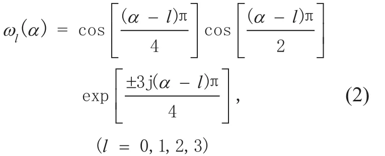
where α is the order of 4-WFRFT to control weighting coefficients and its period is 4.
For a sequence of length N, the α-order 4-WFRFT matrix can be defined as

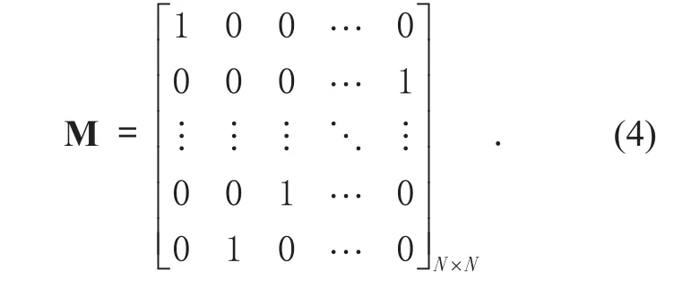
where F0= I is the identity matrix. F is the N-point normalized DFT matrix withand (·)Hdenotes the Hermitian transpose of the matrix. M denotes the reverse matrix which is defined by
2.2 8-Weighted-type fractional Fourier transform
M-WFRFT is a general form of 4-WFRFT and has some relationships with 4-WFRFT. In this paper, 8-WFRFT is adopted. According to the mathematical explanation of M-WFRFT [15],the 8-WFRFT of discrete-time signal g(n) can be expressed by

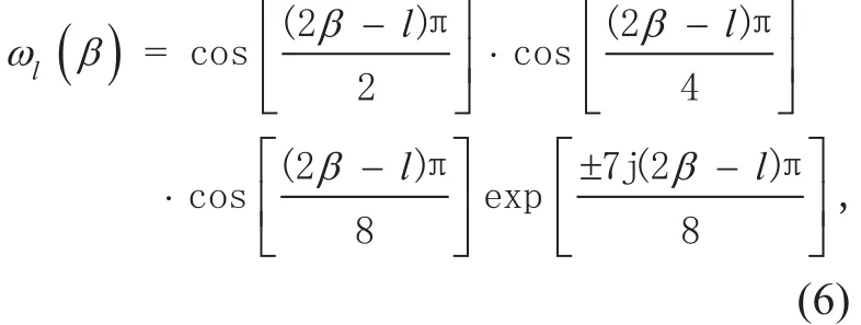
where l=0, 1, ..., 7. β is the order of 8-WFRFT with the period of 8.
Thus, the β-order 8-WFRFT matrix can be written as

WFRFT has the property [10]:

Thus, the expansion of (5) can be obtained as
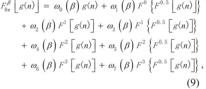
The β-order 8-WFRFT of g(n) can be regarded as the combination of the two components: the 4-weighted sum form of g(n) and the 4-weighted sum form of, as followed

2.3 STBC based transmission model
When the number of transmit antennas Ntis over 2, the STBC scheme can not satisfy the maximum diversity gain and the maximum coding rate at the same time [5]. In order to obtain the maximum diversity gain, when Nt=3, the encoding matrix can be expressed by

where (·)*denotes the complex conjugate.
By utilizing the orthogonality, the received signal can be written as

where I is the identity matrix, x denotes [x1x2x3x4]Tand n denotes the noise vector.
Then the maximum likelihood detection(MLD) is adopted for each element of x, as followed
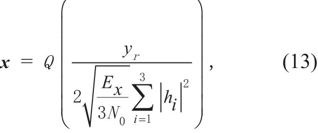
where Q(·) is defined by

III. 8-WFRFT BASED THREE-BRANCH TRANSMISSION METHOD
3.1 Generalized model
In figure 1, the 8-WFRFT based multi-antenna transmission scheme is depicted. The transmitter consists of one 8-WFRFT module and combiner, three delay regulators and three transmit antennas. The original signal is first sent into 8-WFRFT module and decomposed into eight sub-signals. Then, the eight sub-signals are converged into three component signals by the same carrier pattern. The three signals are SC signals, MC signals and HC signals, respectively. They are simultaneously sent into delay regulators for signal synchronization. Then, they are transmitted via three independent antennas. At the receiver, the signal is received by single antenna. An 8-WFRFT inverse transformation module is employed.The feedback parameters are sent to the transmitter from the receiver.
3.2 Signal model
Assume that the original signal is g(n), n = (1,2, …, N). The output signals of the β-order 8-WFRFT and combiner module are expressed by
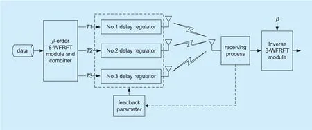
Fig. 1. Framework of the proposed transmission scheme.
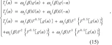
The signals are simultaneously transmitted via three independent antennas. At the receiver, the received signal can be described by

Then, the received signal is sent into the 8-WFRFT inverse module. As discussed in Section II, the β-order 8-WFRFT inverse transformation is the -β-order 8-WFRFT. So the estimated value of the original signal can be described as

3.3 Theoretical BER analysis
The BER of Quadrature Phase Shift Keying(QPSK) modulation over an AWGN channel can be written as

where εbis the bit energy and n0is the variance of the white Gaussian noise.
The channel used in [11] has several random deep fading points. Each fading point has amplitude attenuation of μ and the corresponding energy has attenuation of μ2.
In the time-domain fading channel, there are M time-domain fading points. To SC sys-tem, the energy of each fading point has attenuation of μ2, and the energies of the others are constant.
The BER expression of SC system is the average of each point energy, expressed as

where N denotes the number of total transmitted bits.
To MC system, the attenuation energies of M fading points can be evenly dispersed on all the frequency-domain points. The BER of MC system can be calculated as

In the frequency-domain fading channel,the attenuation situations of SC and MC signals are opposite to those in the time-domain fading channel.
In the doubly-selective fading channel,there are M time-domain fading points and M frequency-domain fading points. Combining(19) and (20), the BER expression of SC signal(MC signal) can be revealed as followed
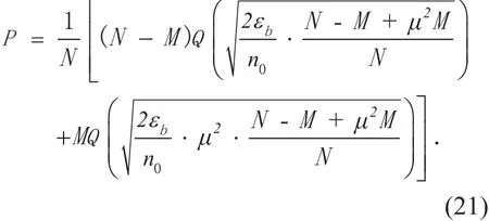
4-WFRFT is the linear combination of SC and MC schemes. The BER expression of 4-WFRFT scheme in time-domain fading channel can be revealed as

Combining to (21), (22) and (23), the BER expression of 4-WFRFT signal in doubly-selective fading channel can be derived as followed
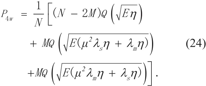
Specially, the 4-WFRFT signal degrades to SC signal at λs=1 and MC signal at λm= 1.Thus, (24) can degrade to (21) at λs=1(λm=1).
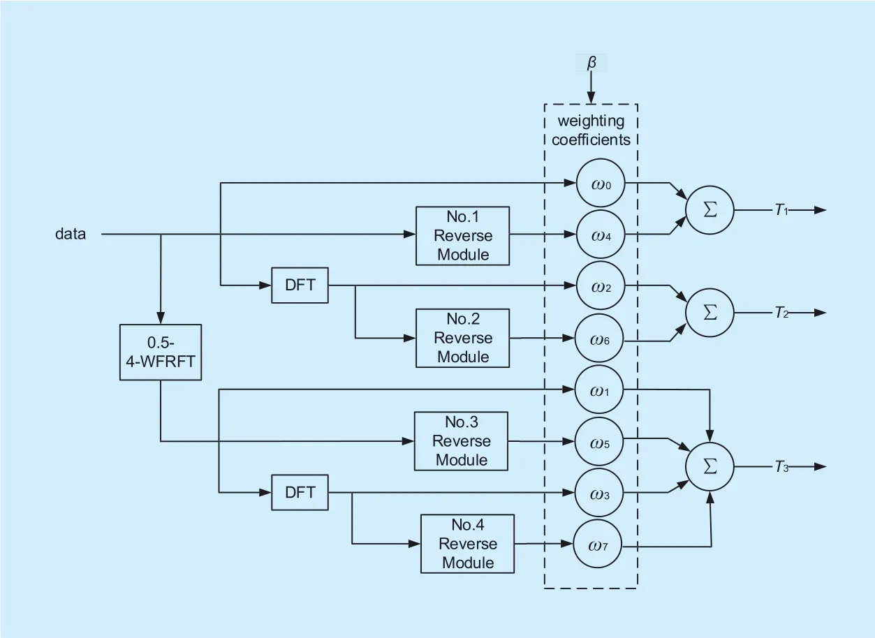
Fig. 2. β-order 8-WFRFT module and combiner.
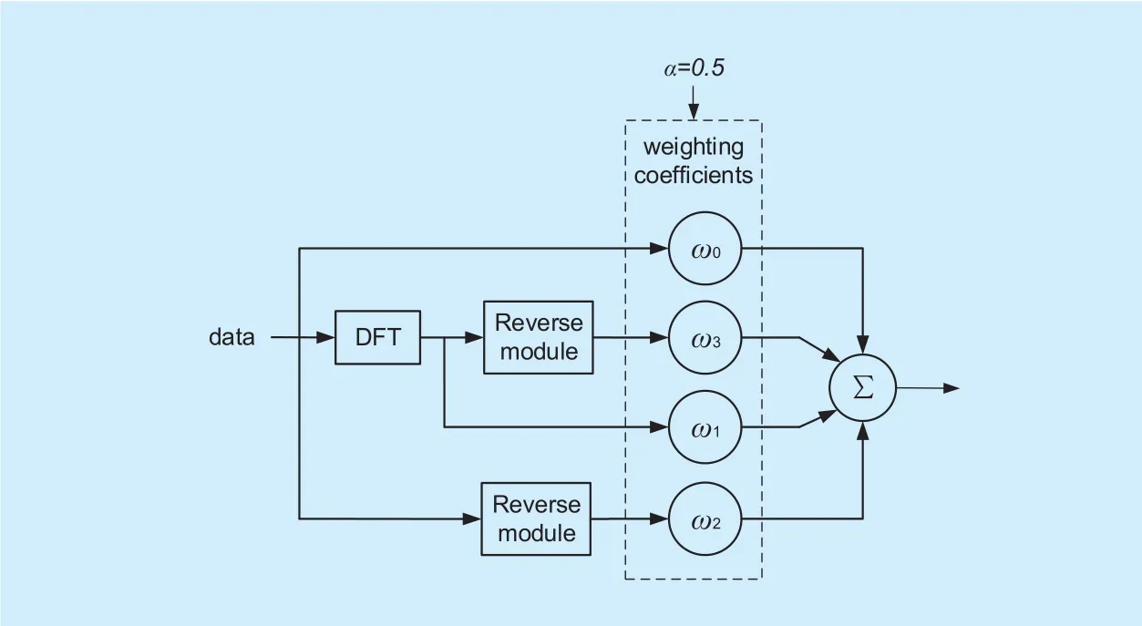
Fig. 3. 0.5-order 4-WFRFT module.
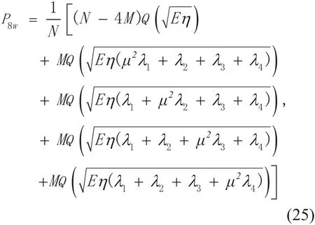
According to figure 2, the 8-WFRFT signal can be seen as the superposition of two SC and two MC component signals. When the order of 4-WFRFT is 0.5, there is λs= λm=0.5.The BER expression of 8-WFRFT system in doubly-selective fading channel can be revealed as
where
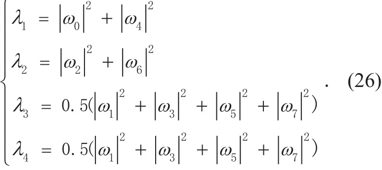
ωl(l =0,1 …,7) is an abbreviation for ωl( β)( l= 0,1 …,7)
3.4 Transmitting power analysis
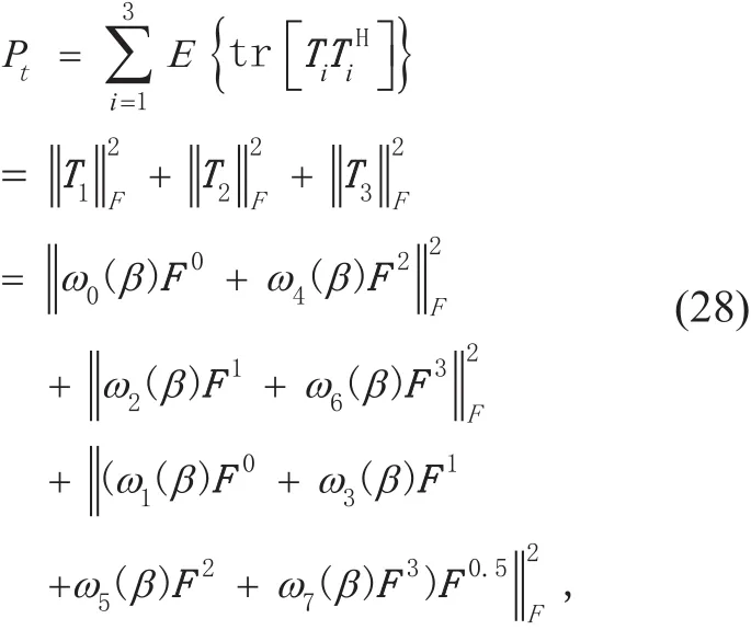
The power of the signal can be denoted by the Frobenius-norm (F-norm) of the signal matrix.The total normalized transmitting power of the proposed scheme can be expressed as

where E(·) represents the expectation and tr(·) represents the trace of the matrix.
Set A=(aij)n×n∈ Cn×n, F-norm has the property

where U is the unitary matrix.
As F is the N-point normalized DFT matrix, it is the unitary matrix. Therefore

S e t m,n∈(0,1,…,7) , i f ωm (β)ωn (β)≥0, there is

In the same way,


From (30), (32) and (33), there is

In another way, if ωm(β)ωn(β)≤0,there is

Then,

Anyhow, the whole normalized transmitting power of the proposed scheme can be demonstrated by

Consequently, the whole normalized transmitting power remains 1. The weighting coefficientscan be regarded as the parameters of power allocation. The normalized power distribution diagram of the three component signals is shown in figure 4. The three curves vary with β periodically. The energy distributions of the three signals are uniform.Meanwhile, as depicted in figure 4, the period of the order β for the three signals is 4.
3.5 Transmission rate analysis
As discussed in Section II, when STBC based three-antenna scheme is adopted, there are four symbols transmitted in eight symbol periods. Thus, the transmission rate is 0.5.In the proposed scheme, the symbols transmitted from three antennas at the same time are different in each symbol period. But only the sum of three transmitted symbols at the receiver can restore the estimation of the original signal. So the transmission rate of the proposed scheme is 1 which is twice as that of the STBC based transmission scheme.
3.6 Power spectrum analysis
Assume that the original sequence is {xn}, it can be expressed as

where δ (·) is the impulse function.
The impulse response and the transfer function of pulse shaping filter are gT(t) and GT(f), respectively. The output of the baseband signal can be expressed as

The power spectrum can be expressed as
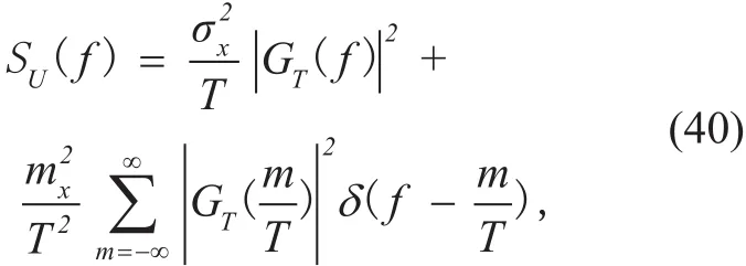
where mxandare the mean and variance of {xn}, respectively. The first item of SU(f)is continuous spectrum and the second one is discrete spectrum.
In this case, QPSK modulation is considered and the order of 8-WFRFT β is 2.5. The normalized power spectrum of QPSK-WFRFT modulated signal is shown in figure 5. When adding zero sequence of length N for the signal to be sent, the proposed scheme has the same transmission rate as STBC scheme. In this case, the normalized power spectrum of the extended QPSK-WFRFT signal is shown in figure 6.
The distributions of power spectrum in figure 5 and figure 6 are almost the same. It is because that the zero padding in time domain can be seen as the equivalent to the interpolation in frequency domain. It will not improve the frequency resolution of the signal. In addition, no new spectrum appears in figure 6.
3.7 Low complexity
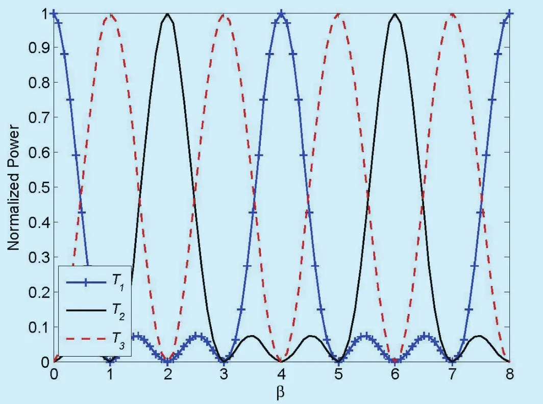
Fig. 4. Normalized power of the three transmitted signal.
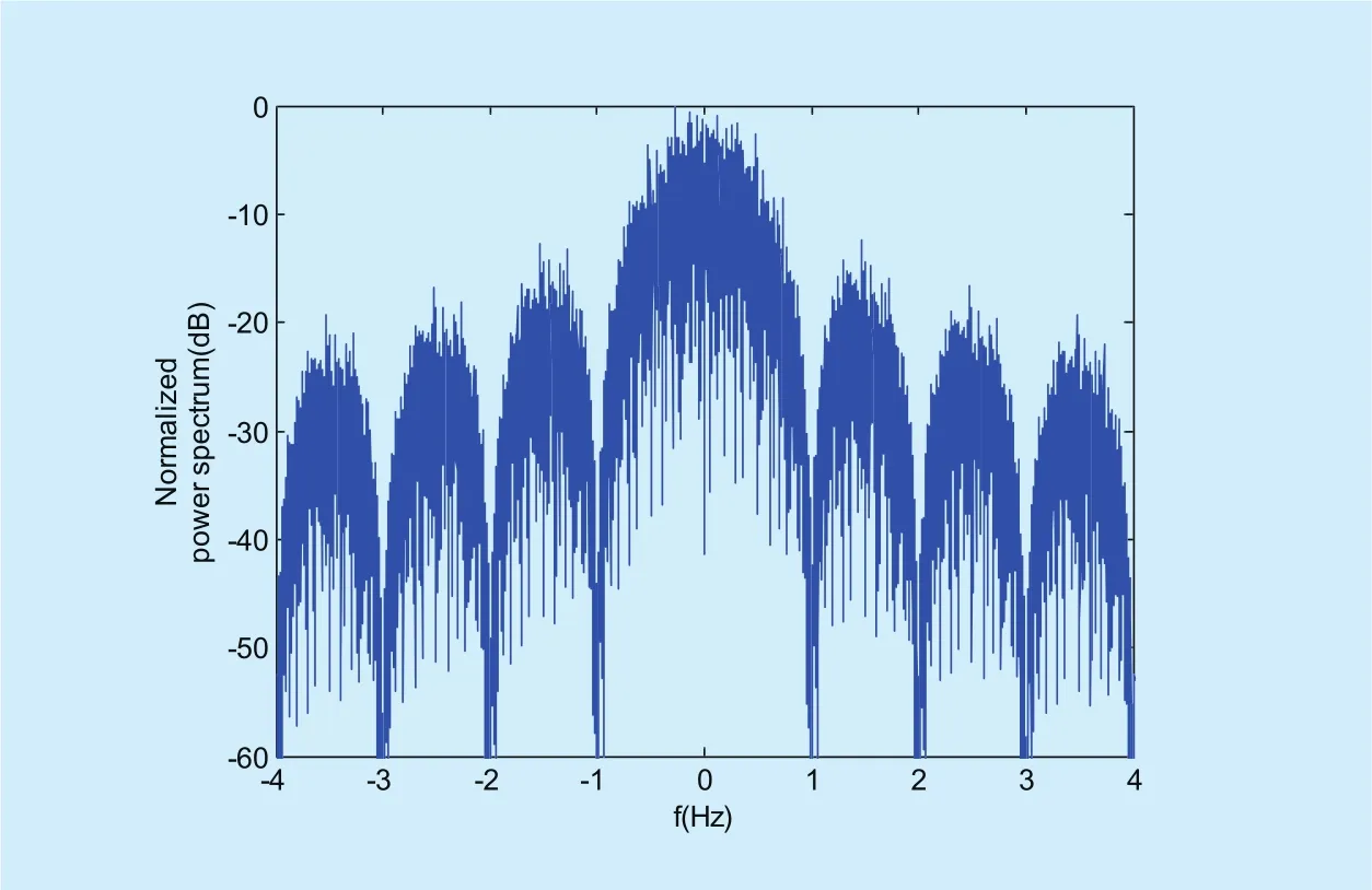
Fig. 5. Normalized power spectrum of the QPSK-WFRFT signal.

Fig. 6. Normalized power spectrum of the extended QPSK-WFRFT signal.

Table I. Complexity requirements on implementation of the proposed scheme.
From the analysis of Section II, the complexity of STBC is the same as that of maximum likelihood detector (MLD) [5].
The maximum likelihood solution for x can be expressed as

where ym×1is the received signal vector from m antennas, xn×1is the transmitted signal vector, Hm×nis the channel matrix, S is the M-ary constellation points set .
In the existing literature [18], the complexity of MLD is quoted as Mn. It increases with the transmitted antennas. In this paper, m=1,n=3. So, the complexity of the STBC based three-antenna scheme requires M3hypotheses.
The proposed transmission scheme has low computational complexity. The complexity of the whole system mainly comes from β-order 8-WFRFT module. As shown in figure 2, the implementation of 8-WFRFT module requires one 0.5-order 4-WFRFT operation, two DFT operations, four reverse operations and eight multiplication calculations. The complexities of reverse operation and additive operation are too low and can be ignored in the computing process. The computational complexity of DFT module is O(NlogN) and that of each multiplication is O(N). The 0.5-order 4-WFRFT module as shown in figure 3 requires O(NlogN+4N) operations. Thus, the computational complexity of the 8-WFRFT module is O(3NlogN+12N). It increases limited complexity, compared to 4-WFRFT. The details of computational complexity are shown in table 1.
IV. NUMERICAL RESULTS AND DISCUSSION
In this section, the transmission schemes have three transmit antennas and one receive antenna. The simulations assume that the systems can achieve accurate synchronization. In order to ensure the same transmission rate as STBC based scheme, zero sequence of length N is added to the signals after delay regulating in the proposed scheme.
The numerical results of the transmission scheme under different fading channels used in [11] are shown. In the channel, there are several random deep time-domain fading points or frequency-domain fading points.Each fading point has amplitude attenuation of 10dB. In this channel model, it is easier to obtain channel state information which can contribute to qualitative analysis and theoretical analysis.
Set ‘t’ and ‘f’ to represent the numbers of time-domain fading points and frequency-domain fading points in the channel, respectively. In the following simulations, for time-domain fading channel, t=3, f=0; for frequency-domain fading channel, t=0, f=3; for doubly-selective fading channel, t=3, f=3.
4.1 MSE and BER performance comparisons
In this case, Binary Phase Shift Keying(BPSK) modulation is adopted and the order of 8-WFRFT β is 2.5. The three channels are all doubly-selective fading channels.
The mean square error (MSE) is defined as

The MSE and BER performance comparisons of 8-WFRFT based transmission scheme and STBC based transmission scheme are shown in figure 7. The curves of the two schemes overlap at low Eb/N0. When Eb/N0is over 4dB, the curve of the proposed scheme is lower than that of the STBC based scheme.The gap of the curves gets bigger as Eb/N0increases. Thus, the proposed scheme outperforms the STBC based scheme in terms of MSE and BER.
4.2 BER performance comparison in diff erent scenarios
In this case, BPSK modulation is considered and β is 2.5. The BER performances of the proposed scheme and STBC based transmission scheme over different scenarios are shown in figure 8.
The scenarios are considered as follows
In Scenario C1, the Channel 1, 2, 3 are all doubly-selective fading channels.
In Scenario C2, the Channel 1, 2, 3 are frequency-domain fading channel, time-domain fading channel and doubly-selective fading channel, respectively.
The Channel 1, 2, 3 in Scenario C3 are time-domain fading channel, frequency-domain fading channel and doubly-selective fading channel, respectively.
As depicted in figure 8, the proposed transmission scheme provides performance improvement at high Eb/N0, compared to STBC based transmission scheme.
For the STBC based scheme, the BER performance in Scenario C1 shows the worst.There is serious doubly-selective fading in each of the channels in Scenario C1. The case of the fading channels in Scenario C2 is opposite to that in Scenario C3. In the two channels of Scenario C2 and C3, there are frequency-domain fading and time-domain fading, respectively. The signals transmitted in Channel 1 and 2 are both time-domain signals. Thus,the BER performance curves in Scenario C2 and C3 are almost the same. They are both lower than the BER curve in Scenario C1. By contrast, the BER performance curves of the proposed scheme have little difference in the three different scenarios.
When Eb/N0is over 5dB, the BER curve of the proposed scheme is lower than that of the STBC based scheme in Scenario C2 and C3.While in Scenario C1, when Eb/N0is over 4dB,the BER performance of the proposed scheme shows better. Thus, the proposed transmission scheme has strong anti-interference capability,especially in severe channels.
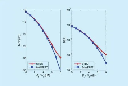
Fig. 7. MSE and BER performance comparative analysis of the two schemes.
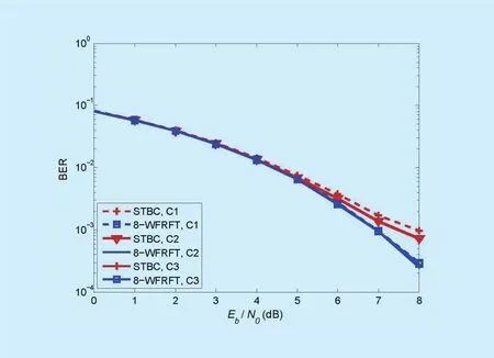
Fig. 8. BER performance comparison of BPSK modulated systems.
4.3 BER performance comparison of diff erent modulated schemes
In this case, β is 2.5. The number of the symbols is 128. BPSK modulation and QPSK modulation are adopted. The three channels are all doubly-selective fading channels.
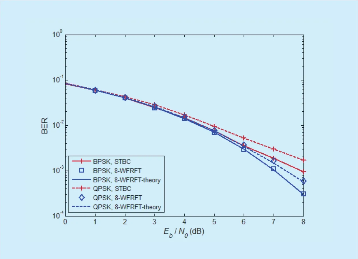
Fig. 9. BER performance comparison of BPSK and QPSK modulated systems.
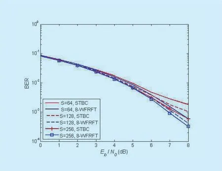
Fig. 10. BER comparison of QPSK modulated systems with different subcarrier numbers.
As shown in figure 9, the BER performances of the two transmission schemes with BPSK modulation are better than those with QPSK modulation. When Eb/N0is over 4dB, the BER curve of the proposed scheme with BPSK modulation is lower than that of the STBC based scheme. The advantage of the proposed scheme is more obvious with the increase of Eb/N0. So, the proposed scheme with BPSK modulation has better BER performance,especially at high Eb/N0. When QPSK modulation is considered, the same conclusion can be drawn. In a word, the proposed scheme is obviously superior to the STBC based scheme,no matter which modulation is chosen.
4.4 BER performance of the schemes with diff erent subcarrier numbers
In this case, QPSK modulation is considered and β is 2.5. The three channels are all doubly-selective fading channels. The numbers of the used subcarriers are 64, 128 and 256,respectively.
As shown in figure 10, ‘S’ denotes the number of subcarriers, the figure shows the effect of the numbers of subcarriers on BER performance. The BER performance of the proposed scheme is better than that of the STBC scheme with the same number of subcarriers. With the increase of subcarrier numbers, the BER curves of the two schemes decline dramatically. The difference of the curves in the STBC scheme is greater than that in the proposed scheme. So the STBC scheme is more susceptible to the numbers of subcarriers. While the decrease of subcarrier numbers has little effect on the BER performance of the proposed scheme.
4.5 BER performance comparison of the proposed scheme with diff erent orders
In this case, BPSK modulation and QPSK modulation are adopted, respectively. The three channels are all doubly-selective fading channels.
As shown in figure 4 (Section III), the period of the order β for the three transmitted signals is 4. According to the properties of β, when β is an integer value, such as 0, 1, 2,3, one ofis 1, the others are 0.For the proposed scheme, this is equivalent to single-antenna system. It has no better performance compared to multi-antenna system.When the order β is 0.5, 1.5, 2.5 or 3.5, the power distributions of the three transmitted signals are uniform. So the BER performance of the proposed scheme is relatively better.
Figure 11 shows the BER performance comparison of BPSK modulated systems with different orders. The BER performance of β=0.5 is almost the same as that of β=3.5.
It is the same case when β=1.5 and β=2.5.Obviously, the BER performance shows better at β=1.5 (or 2.5).
Similarly, Figure 12 shows the BER performance comparison of QPSK modulated systems with different orders. As the curves are intensive, the range of Eb/N0in figure 12 is from 6dB to 8dB. When β=0, only SC signal is transmitted via single antenna. So the BER performance shows the worst. The BER performance grows better gradually when β is from 0.5 to 2 (from3.5 to 2). The curve with β=1.5 is extremely close to that with β=2.5.From the whole curve cases of figure 12, the curve with β=2.5 declines the fastest. The BER performance of that is the best. Thus, the optimal choice is β=2.5.
V. CONCLUSION
In this paper, an 8-WFRFT based multi-antenna transmission scheme is presented for better BER performance with low complexity in MIMO systems. It can achieve the compatible communication with 8-WFRFT and multi-antenna technology. In the proposed scheme, the three transmitted signals contain SC, MC and HC signals, respectively. They have mathematical constraint relations among themselves and show strong anti-jamming capability.Then BER performance, transmitting power,transmission rate, power spectrum and computational complexity of the proposed scheme have been discussed in detail. Moreover, the BER performances of the proposed scheme in different channels, modulated systems, numbers of subcarriers and orders are demonstrated via simulations. Numerical results indicate that the proposed transmission scheme is superior to the STBC based transmission scheme in terms of fading resistance.
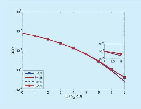
Fig. 11. BER comparison of BPSK modulated systems with different orders.
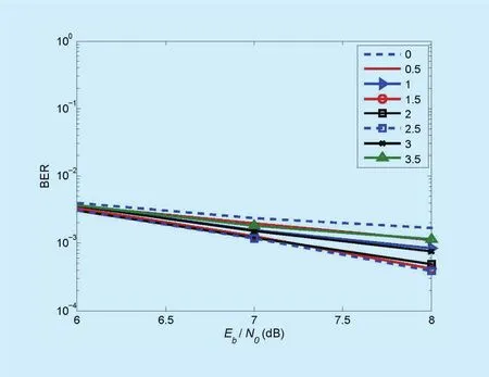
Fig. 12. BER comparison of QPSK modulated systems with different orders.
ACKNOWLEDGEMENTS
The authors would like to thank the reviewers for their detailed comments, which have helped improve the quality of this paper. This work has been supported by the National Basic Research Program of China (2013CB329003),the National Natural Science Foundation Program of China (No. 61671179) and Funds for Science and Technology on Information Transmission and Dissemination in Communication Networks Laboratory (EX156410046).
- China Communications的其它文章
- DNN-Based Speech Enhancement Using Soft Audible Noise Masking for Wind Noise Reduction
- Delay-Based Cross-Layer QoS Scheme for Video Streaming in Wireless Ad Hoc Networks
- An MAC Layer Aware Pseudonym (MAP) Scheme for the Software De fined Internet of Vehicles
- Asymptotic Analysis for Low-Resolution Massive MIMO Systems with MMSE Receiver
- Golay Pair Aided Timing Synchronization Algorithm for Distributed MIMO-OFDM System
- Joint Non-Orthogonal Multiple Access (NOMA) &Walsh-Hadamard Transform: Enhancing the Receiver Performance

