Delay-Based Cross-Layer QoS Scheme for Video Streaming in Wireless Ad Hoc Networks
Shu Fan, Honglin Zhao*
1 Communication Research Center, Harbin Institute of Technology, Harbin 150080, China
2 Audio-Visual and Image Technology Department, Criminal Investigation Police University of China, Shenyang 110854, China
Abstract: With correlating with human perception, quality of experience (QoE) is also an important measurement in evaluation of video quality in addition to quality of service (QoS).A cross-layer scheme based on Lyapunov optimization framework for H.264/AVC video streaming over wireless Ad hoc networks is proposed, with increasing both QoE and QoS performances. Different from existing works, this scheme routes and schedules video packets according to the statuses of the frame buffers at the destination nodes to reduce buffer under flows and to increase video playout continuity. The waiting time of head-ofline packets of data queues are considered in routing and scheduling to reduce the average end-to-end delay of video sessions. Different types of packets are allocated with different priorities according to their generated rates under H.264/AVC. To reduce the computational complexity, a distributed media access control policy and a power control algorithm cooperating with the media access policy are proposed. Simulation results show that, compared with existing schemes, this scheme can improve both the QoS and QoE performances.The average peak signal-to-noise ratio (PSNR)of the received video streams is also increased.
Keywords: cross-layer control; Lyapunov optimization; wireless ad hoc networks; video streaming
I. INTRODUCTION
With a significant increase in the use of smart multimedia devices equipped in wireless Ad hoc networks, real-time multimedia applications such as video streaming application have become major services[1] that play important role in military, disaster relief and public safety. Consequently, techniques for improving quality of video transmitted in wireless Ad hoc networks have received significant attention.
Video streaming applications are delay-sensitive, as video packets arriving after the playout deadline are assumed to be lost. Large amount of video packets lost will result in great reduction of quality of video. In addition to QoS, QoE also has an important impact on quality of video[2]. Video continuity is a major performance metric impacting on QoE that is the length of time the video is being played without interruptions[3]. Video discontinuity can also reduce the quality of video, and the main cause of video discontinuity of video streaming is due to frame buffer under flow.
Existing works on video transmission in wireless Ad hoc networks mainly aim to reduce the end-to-end delay of video sessions to increase quality of video. However, these works ignore the states of frame buffers at the destination nodes in scheduling, which leads that the video sessions in danger of frame buffer under flow can not be allocated transmission opportunities of video packets first and the video playout continuity is reduced. To the best of our knowledge, there is still no QoS scheme that schedules video packets according to states of frame buffers to increase video playout continuity for multi-hop wireless networks.
In this paper, based on Lyapunov optimization framework[4], we propose a cross-layer control video transmission algorithm that supports H.264 in wireless Ad hoc networks,aiming to increasing both QoE and QoS performances. The key contributions of this paper can be summarized as follows:
The paper proposes a cross-layer QoS scheme that can improve quality of video encoded/decoded with H.264/AVC in wireless Ad hoc networks through routing and scheduling video packets according to the statuses of the frame buffers at the destination nodes.
The algorithm uses information of waiting time of head-of-line packets of data queues in scheduling to reduce the average end-to-end delay of video sessions.
Different types of packets are allocated with different priorities according to their generated rates under H.264/AVC.
A distributed media access control policy is designed to reduce the computational complexity. Simultaneously, a power control algorithm is proposed to equalize the transmission capacities of links in the networks.
The remainder of this paper is organized as follows. In Section II, the related works are analyzed. Section III introduces the system model. In Section IV, using Lyapunov optimization the algorithm is designed for multi-hop networks, respectively. A distributed scheduling scheme and a power control algorithm is introduced in Section V. The simulation results are given in Section VI. Finally, the conclusions are provided in Section VII.
A cross-layer scheme based on Lyapunov optimization framework for H.264/AVC video streaming over wireless Ad hoc networks is proposed,with increasing both QoE and QoS performances.
II. RELATED WORK
QoS schemes for video transmission focusing on reduction of the end-to-end delay can be applied in different layers of wireless Ad hoc networks, including schemes used in physical layer[5,6], routing schemes[7-10],scheduling schemes[11-13], media access control schemes[14] and cross-layer control schemes[15-18]. [5] proposes a scheme for multi-user video transmission over MIMO(Multiple-input multiple-output) multi-hop wireless networks. In [6], an interference approximation model are developed for increase of video transmission quality. [7] designs a multipath routing protocol based on OLSR.Route recovery and loop detection are also utilized in this scheme. [8] is the extension of[7]. [8] adopts link quality metrics instead of hop-count as routing metrics in path-finding process to enhance video transmission quality.[9] introduces a routing metric that considers link quality parameters from different layers for multi-radio wireless networks. [10]proposes a more flexible multipath selection strategy providing the quasi-disjoint paths for video transmission. Schemes in [11] and [12]both take into account the importance of packets in scheduling of video transmission over 802.11e WLANs. For delay-sensitive applications in energy harvesting wireless networks,[13] adapts scheduling according to both data queue length and energy queue length information. [14] presents a time-slot assignment policy of TDMA (Time division multiple access) system that can provide weighted fairness and jitter minimization over sensor networks. Based on Lyapunov optimization, a joint routing and spectrum sharing scheme for video streaming in proposed in [15]. In [16],routing and flow control are jointly optimized for network utility maximization. Specially,impact of video coding rate is considered.[17] proposes a backpressure-based multirate multicast algorithm providing delay guarantees through combines differential backlog scheduling and novel packet dropping. [18]integrates regulated-contention MAC (Medium access control) into the NUM-based (Network utility maximization) networking stacks for transmission of inelastic flows with strict deadlines. Besides, some other novel schemes are also designed to reduce end-to-end delay and improve QoE[19-21]. [19] designs a packet dropping policy that packets that are expected to be time-expired are discarded in time. In[20], characteristics of delay announcement is studied and a delay announcement scheme is proposed for improvement of QoE. In the scheme, an objective user response function is established. [21] applies device-to-device(D2D) communication in video distribution to meet service demand and proposes a distributed scheme whose robustness in a dynamic communication environment is proved. However, in above works, states of frame buffers at destination nodes are not considered in scheduling. This results in reduction of video playout continuity, for video sessions being faced with frame buffer underflow can not gain transmission opportunities in time.
There are few QoS schemes that consider the states of frame buffers in scheduling for wireless networks[22-24]. In [22], considering increasing the encoder frame generation rate and reducing the decoder playout frame rate can increase video playout continuity, as well as result in playout distortion, the video quality maximization problem and the playout distortion minimization problem are established using Lyapunov optimization framework, and the encoder frame generation interval and the decoder playout frame interval are adjusted jointly to avoid buffer underflow. However,the relay of data between the source nodes and the destination nodes is not considered in [22].In [23], under the assumption that there is no buffer under flow, a scheme that each user estimates its local delay by monitoring the delivery times in a sliding window is proposed.According to the local delay estimated, the buffer size at each destination node is adjusted. [24] extends [23] into the networks utilizing MIMO(Multiple-Input Multiple-Output) in PHY layers. However, both [23] and [24] are designed for one-hop networks.
Different from existing works, in the cross-layer algorithm proposed in this paper,virtual queues that are updated according to the statuses of frame buffers are designed, as well as used as basis for scheduling in video streaming transmission. Specially, this scheme can be utilized in multi-hop networks.
In addition, [25] introduces virtual queues of explicit delay information of head-of-line packets in data queues in Lyapunov optimization to reduce the end-to-end delay as well as to ensure deterministic worst case delay guarantees. However, the network in [25] is assumed to be a one-hop network. In the proposed algorithm, the queue structure is utilized in multi-hop networks.
III. NETWORK MODEL
Consider a wireless network consisting of several nodes. Let the network be modeled by a directed connectivity graph G(N,L), where N is the set of nodes and (i,j)∈ L represents an unidirectional wireless link between node i and node j. Table I summarizes the key notations used in section III.
Video transmission is considered in this model. Let M be the set of unicast video sessions m between source–destination pairs in the network. Each session has one source-destination pair. smis the source node of sessionm, and dmis the destination node of session m.Nsrepresents the set of source nodes and Nddenotes the set of destination nodes. The frames of video stream of session m are encoded into a sequence of video packets at the encoder of sm. The generated video packets are injected into packet buffers of source nodes to transmit.According to the encoding algorithm H.264/AVC [26] used in this paper, frames are divided into three basic common types that are I-frames, P-frames and B-frames. K denotes the set of the basic common type k of frames.Packets from the source nodes traverse one or multiple wireless hops before arriving at the destination nodes. Video packets of session m arriving at the packet buffer at dmare decoded and injected into the frame buffer to playout.Video frames arriving at the frame buffers after the playout deadline are assumed to be lost. We also assume that the frames in the frame buffers are arranged in display order. A typical video transmission scenario is shown in figure 1.
The available spectrum is organized in two separate channels. Qne channel is common control channel that is for spectrum access negotiation of nodes on frequency fc. The other channel is data channel that is for data transmission on frequency [fmin, fmax]. Here, fcis not in [fmin, fmax]. Each node is equipped with two transceivers. One is employed on the common control channel, and the other is used for data transmission. Each node can either transmit packet or receive packet at the same time.
The system is assumed to run in a time-slotted fashion. At the beginning of each time slot, nodes contend for spectrum access on the control channel to obtain data transmission opportunities. The nodes that obtain data transmission opportunities keep on data transmission on data channel until the end of the time slot. In addition, on the common control channel, nodes can exchange channel access negotiation information and local information including lengths of queues and weight values of nodes. Each node can gain information from other nodes by monitoring the control channel.

Fig. 1. Encoding-and decoding flow of video.
αnj(t)∈ {0,1} is used to indicate whether link (n,j) is used to transmit packets in time slot t. αnj(t)=1 implies that link (n,j) is scheduled for data transmission. In this model,scheduling is subjected to the following constraint:
Constraint (1) implies that each node is equipped with only one radio such that it may either transmit or receive data during each time slot.
In the networks, there is a link (n,i). Node n is the sending node and node i is the receiving node of the link., the transmission power of node n is subjected to the following constrain:


where k'is the target node of sending node k.Knidenotes the processing gain of CDMA system. Gniis the transmission loss from node n to node i, and in this paper,, where dniis the distance between node n and node i. nirepresents the noise at node i. The transmission capacity of link (n,i) can be derived as:
where B denotes the bandwidth of data channel.
In the wireless networks, a link is shared by several sessions. In the same time slot, the total data transmission amount of all sessions on one link is constrained by the maximum data amount can be transmitted on this link in a time slot. The constrain is as follow:

where S( n, i) is the set of the sessions transmitted on link (n, i). tslotis the duration of a time slot. Cni(t ) denotes the transmission capacity of link (n, i) in time slot t.(t) is the transmission amount of packets of session m on link (n, i) in time slot t.
IV. DESIGN OF CROSS-LAYER SCHEME
In this section, the cross-layer scheme is designed. The scheme is based on the Lyapunov optimization framework. The minimization of the conditional Lyapunov drift leads to the joint routing and scheduling algorithm.Different from existing backpressure-based algorithms, two novel virtual queues are introduced into the Lyapunov function. One virtual queue proposed in section 4.3 indicates waiting time of the head-of-line packet in data queues. The other virtual queue proposed in section 4.4 reflects change of statuses of frame buffers at the destination nodes. More vital information is considered in routing and scheduling by adding these two virtual queues into the Lyapunov function. Specially, the proposed scheme is designed for video streaming encoded and decoded using H.264/AVC. In table III, the notations used in section V are summarized.
4.1 Design of data queue
In node n, packets of type k in session m are buffered in queue. In each time slot,the queue backlog(t ) is updated as:
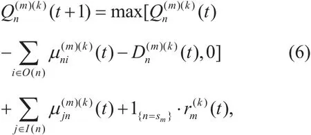

where Cni(t ) denotes the transmission capacity of the link (n,i) in time slot t.(t) ∈ [0,Dmax] represents the number of packets of type k in session m that are dropped by node n in time slot t. Dmaxdenotes the maximum amount of data that are allowed to be dropped by one node in one time slot.(t ) is the amount of packets of type k in session m being injected into the network layer of the source node of session m in time slot t. Considering that the video files to be transmitted are determined,(t) is a predefined value in this paper. In the destination node dmof session m∈M,(t)=0.
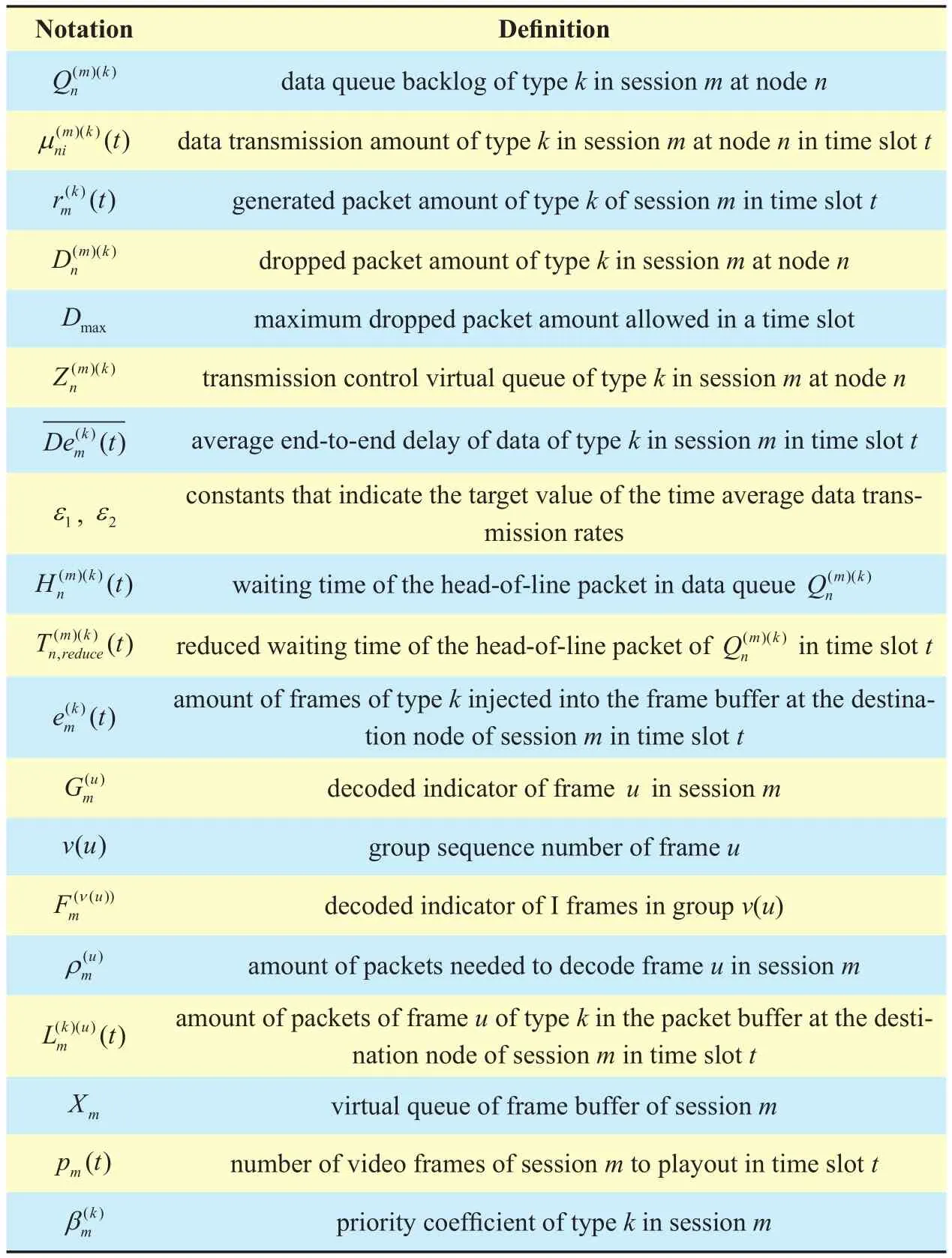
Table II. Notations in section IV.
4.2 Design of Virtual Queue to Control Transmission Rate
In node n≠dm, virtual queuesare used to control data transmission rates for type k of session m. In each time slot t, the virtual queue is updated according to (8) below.Here, constant ε1> ε2>0 and(0)=0.is the average end-to-end delay of data of type k of video session m in time slot t.denotes the playout deadline of video packets of session m. ε1and ε2are constants that indicate the target values of the time average data transmission rates. Under different QoS states of video sessions, if the virtual queuecan be stabilized, the time average transmission data rates of type k in session m will approach the target values.
4.3 Waiting time of the head-of-line packet


If we define

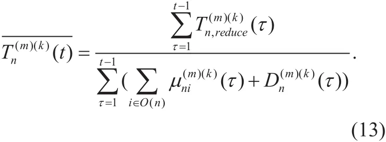
then, (10) can be transformed into (12) below.(t ) can be calculated through checking cases of different(t) and(t ).However, the computational complexity of the calculation is too high. To reduce the computational complexity,is used instead ofthat can be calculated using following equality:
4.4 Design of virtual queue of frame buffer
In each time slot, the packets in the packets buffer of the destination nodes of each session are decoded into video frames. The video frames are then injected into the frame buffers.(t ) represents the number of frames of type k in session m injected into the frame buffer of the destination node of session m in time slot t. In this paper, packets of type k1,k2 and k3 are packets of I-frame, P-frame and B-frame, respectively. According to H.264/AVC, in each time slot,andare updated as follows:


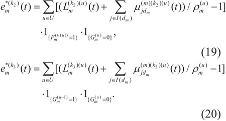
According to the update methods,the following inequality can be derived:
To reduce the underflow and increase the playout continuity of the video sessions, a virtual queue Xmis designed to reflect the statuses of frame buffers. The virtual queue Xmis maintained at the destination node dmof session m. In each time slot t, the queue Xmis updated as:

Here pm(t) is the number of video frames of session m removed from the frame buffer to playout in time slot t. In this paper, pm(t) is set to be a constant whose value is pn.
If each virtual queue Xmis stable, according to the necessity and suf ficiency for queue stability [27], the following inequality can be derived.

where the time average value of time-varying variable x(t) is denoted by. Inequality (22) implies that the time average number of frames of session m which are removed from the frame buffer to playout is lower than the time average number of frames arriving at the frame buffer. Thus, the underflow of frame buffers can be reduced.
4.5 Dynamic algorithm via Lyapunov Optimization
Let Θ(t) =[Q( t), Y( t), Z( t),X( t)] be the network state vector in time slot t. Define the Lyapunov function as:
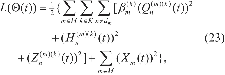


The conditional Lyapunov drift in time slot t is:

The inequality (27) can be derived. Then,Ψ1, Ψ2, Ψ3and B''can be evaluated as (28)to (31). B'is a constant that satisfies the inequality (32).
To stabilize the queues in the Lyapunov function, the conditional Lyapunov drift or the expectation of the conditional Lyapunov drift should be minimized. In (27), the expectation of the conditional Lyapunov drift, E{ΔΘ(t)},is bounded by the right-hand-side of (27).Therefore, to minimize E{ΔΘ(t)}, the main design principle of the algorithm DCCIC (Delay-basedCross-LayerControl forImproving Video PlayoutContinuity) is defined to minimize the right-hand-side of (27). The algorithm includes four components:
Joint routing and scheduling at the relay nodes:In each time slot, at each relay node n,routing and scheduling decisions(t) for type k in session m can be made by solving the following problem:

subject to (1), (2), (7).
First, the best session m*and the best type k*on link (n,i) should be calculated through using:

Then, the weight value of link (n,i) can be derived as:

The routing and scheduling problem can be transformed into the following problem:

subject to (1), (2),

To solve the problem (36), the central node of the network requires global knowledge and gain all (Ic,Pc) that satisfies the constraints of problem (36). Icis the set of links that can transmit data simultaneously, and Pcis the set of transmission powers that can be used on links of Ic. The solutions of problem (36) isfrom (Ic,Pc), which can maximize
The computational complexity of the optimal central algorithm to resolve the problem(36) is O(|N|3). Here, |N| is the number of nodes in the network. Obviously, it is dif ficult to utilize the central algorithm in large-scale networks. To reduce the computational complexity of scheduling and routing, a distributed media access control scheme is proposed in section 5.1.
Joint routing and scheduling at the destination nodes:Node l≠dmare nodes that are one hop away from destination node dmand try to transmit data to dm. In each time slot,scheduling decisions of each node l for type k in session m can be made by solving the following problem:

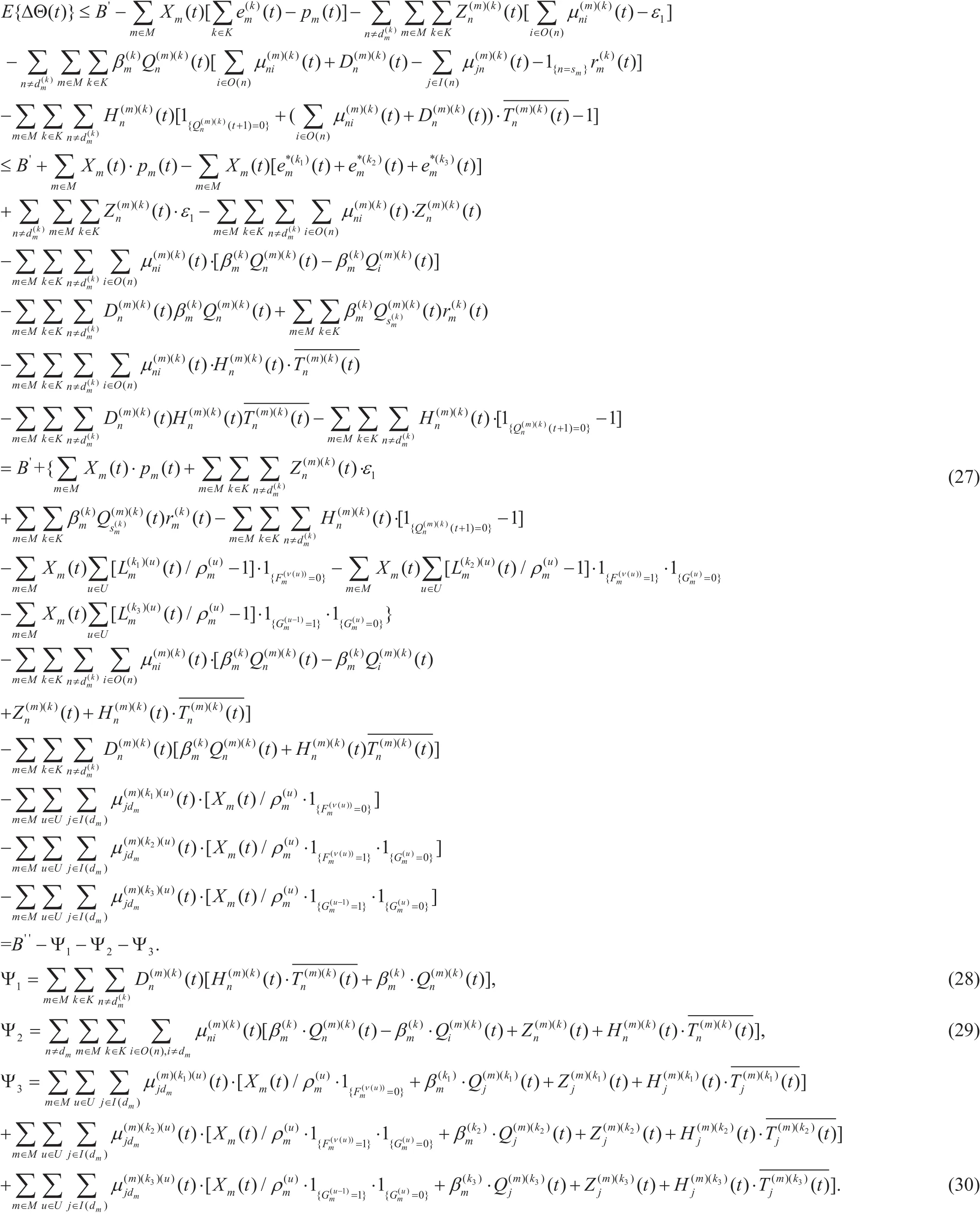

subject to (1), (2), (7).
To solve the problem (37), the central nodes of the network requires global knowledge and gain all (Ic,Pc) , where Icis the set of links that can transmit data simultaneously and is also the set of links that are Id= ((j, dm),m ∈ M, j∈ I( dm)), and Pcis the set of transmission powers that can be used on links of Ic. The solutions of problem (37) isfrom (Ic,Pc), which can maximize Ψ3. The session m*, the type k*, the frame u*to be transmitted by node j∈I( dm) and the weight value wjof node j, can be calculated using following equalities:

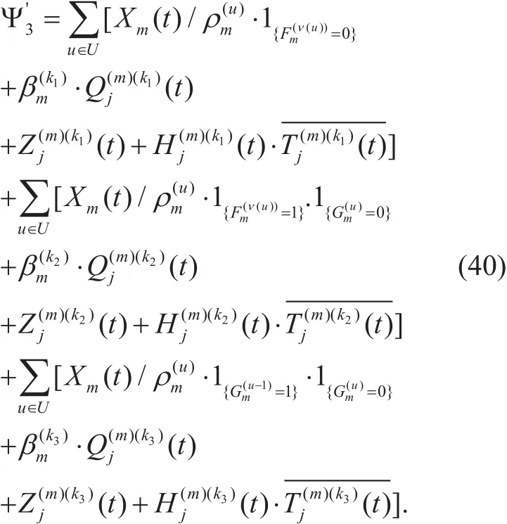
Packet drop decision:For each node n,chooseto solve:

if there are packets in queue,(t ) should be Dmax. To reduce the number of dropped packets, the packet drop decision scheme is designed as: in time slot t, if there are packets in data queue,andpackets at the head of the queuewill be dropped.
Update of queues:Q(t), Z(t), H(t) and X(t)are updated using (6), (8), (14) and (21) in each time slot.
V. DISRIBUTED SCHEDULING AND POWER CONTROL SCHEME
According to the analysis in section 5.5, the computational complexity of optimal central algorithm for routing and scheduling problem reach O(|N|3), where |N| represents the number of nodes in the network. To reduce the computational complexity of routing and scheduling,we design a distributed media access control scheme. In addition, to equalize the transmission capacities of links in the networks, a power control algorithm is designed.
5.1 Distributed media access control
In this section, a low-complexity distributed media access control scheme is proposed. In this scheme, nodes contend to access the control channel for data transmission opportunity.The way that nodes contend on the control channel is similar to IEEE 802.11 two-way RTS (Request to Send) and CTS (Clear to Send) handshake. Nodes with higher weight values can enjoy more data transmission opportunity. As illustrated in figure 2, the details of the scheme is as follows.
(i) Assume that |N|, the number of nodes in the network, is known by each node. Rtime is calculated according to |N|. (ii) At the beginning of each slot, each node n broadcasts IUnpacket after a random waiting time RBn∈[0,R time ]. Information of node n in IUnincludes queue lengths, current position. (iii)After listening the control channel and collecting information for Rtime, node n calculates weight values of links according to (35). Destination node i*of node n in this slot is chosen as follows.

The weight value of node n is wn= wni*.Each node i calculates the contention window CWias follows [28].

Here, N means the set of candidate send nodes. Backoff counter for node i is a random value as(v) Then, each node begins to monitoring the control channel. If node ifinds that the control channel has been idle for DIFS+BCi, node i will send RTS packet to its destination node i*which includesand the information about the destination node in plan. (vi) After receiving RTS packet from node i, node i*will begin to implement the power control scheme proposed in section 6.2 if it is idle for data transmission. If the new link (i,i*) is allowed to be established, after a period of SIFS, node i*will send a CTS packet to tell all send node the new transmit powers and transmission durations on each link. Otherwise, node i*replies to i with a NCTS to refuse the establishment of link (i,i*). (vii) After receiving the CTS packet from node i*, all send nodes update the transmit powers, and all idle nodes update their contention windows and backoff counters with deleting node i from the set of candidate send nodes. Node i starts to send data to node i*on data channel. Node i*will reply to i with a ACK packet on data channel after the successful data reception. (viii) After receiving NCTS packet from node i*, Node i and other idle nodes begin to monitor the control channel for further negotiation.
5.2 Power control
The power control algorithm is implemented in the destination node. The design objective of the power control algorithm is to ensure that the SINR at each destination node is SINRth. Assume that there have been n links in the network. The existing links from send nodes to destination nodes are denoted as(x1, y1),(x2,y2),...,(xn,yn). Node xn+1trying to transmit data packets to node yn+1sends a RTS packet on the control channel. After receiving the RTS packet from xn+1, node yn+1begins the computation to gain the transmit powersof all send nodes (x1, x2,...,xn+1) which should guarantee that the following equalities hold:

where i∈[1,n+1]. (44) can be transformed into multivariate equations as follows:

where G, X and S can be denoted as (46),(47) and (48).


5.3 Analysis of computational complexity and capacity region
Based on the distributed media access control scheme, the computational complexity of the joint routing and scheduling scheme in each node should be lower than O(|N|). This means that the computational complexity of the proposed distributed media access control scheme will not increase sharply when network size increases. Then, consider the computational complexity of the power control algorithm.According to (45), each node needs to solve multi-head linear equations to implement the power control algorithm. As matrix G is a |L|dimensional matrix and X is a |L| dimensional vector, the computational complexity of the power control at each node can be O(|L|2).Therefore, the computational complexity of the routing, scheduling and power control at each node is lower than O(|N||L|2).
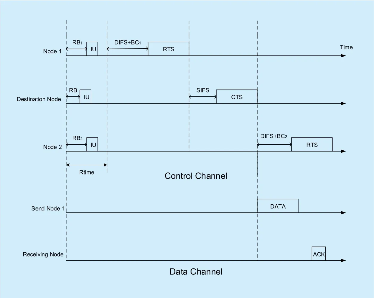
Fig. 2. Medium access control logic.
When the runtime is long enough, effect of the proposed distributed media access control scheme can approach the effect of GMS(Greedy Maximal Scheduling) algorithm which is a central routing and scheduling algorithm. Capacity region of GMS scheme can reach 1/2 capacity region of the optimal central algorithm[29]. Therefore, the capacity region of the proposed distributed scheme can also reach 1/2 optimal capacity region.
In addition, computational complexity of GMS scheme is O(|L|log|L|)[29]. Here, |L| denotes the number of links in the network.
VI. SIMULATION
6.1 Simulation setup
The topology is a multi-hop network with 20 nodes randomly distributed in a square of 30m*30m. In this network, there are two unicast video sessions with randomly chosen sources and destinations. The transmission range of a node is 20m. In the simulation,nodes do not move. Each node is aware of the position information of other nodes in the network. The message broadcasted on the common control channel by any node can be received by any other node. All initial queue sizes are set to be 0.
The video file to be transmitted in the network is “bus.CIF”[30] whose resolution is 352*288. The file is encoded by H.264/AVC JM12.2 software[31], and 30 frames are generated per second. The length of the video file is 5s. The playout deadline is 1s. The time slot duration is equal to the frame duration. The simulation time lasts 180 time slots. The unit of transmission data amount is set as packet.The packet length is 3200bits. The detailed process is as follows. Firstly, the video file is encoded using ldecod.exe in H.264/AVC JM12.2 software package. In the output files,there is a tracefile.dat file that tells the num-ber of packets generated for each frame and their generated time. Then, through simulation, we obtain an error.txt file that tells the sequence numbers of packets dropped in the transmission. An error.txt file can be generated according to these sequence numbers. Using the error.txt file and ldecod.exe in H.264/AVC JM12.2 software package, the video file output.yuv file can be generated. Finally, we can watch the video of output.yuv using openEye YuViewer software, and obtain PSNR of the video of output.yuv using MSU VQMT software.
Prebuffering and rebuffering are implemented at the destination nodes. The rebuffering will be started if there is underflow at frame buffer in any destination node. The video playout continuity is characterized by average playout time ratio that is calculated as:

where Pplayoutratiois the average playout time ratio, Tplayoutdenotes the total time that video files play, and Ttotalis the time simulation lasts.
In this section, the performance of DCCIC is compared with that of MP-OLSR[7], PDAPMF[11] and ROSA-PQM[15]. MP-OLSR is a multipath routing scheme. PDA-PMF is a priority-aware scheduling scheme for H.264/AVC video streaming. ROSA-PQM is a backpressure-based cross-layer algorithm for H.264/AVC video streaming. The spectrum sharing scheme of ROSA-PQM is not applied in the simulation, as there is only one spectrum band on the data channel. The following metrics were measured in the evaluation:throughput, end-to-end delay, playout time ratio, rebuffering times, packet loss rate and PSNR.
In DCCIC, ε1=20, ε2=0,=1s .AODV is used as the routing scheme of PDA-PMF. Number of paths in MP-OLSR is 3. To make MP-OLSR, PDA-PMF, and ROSA-PQM scheme more comparable with DCCIC on routing and scheduling, all the algorithms in the simulation use the distributed media access control scheme proposed in section 5.1 to choose transmission links and power control method proposed in section 5.2 to decide the transmission powers of send nodes. In the distributed media access control scheme, ?=10, γ=10, DIFS=50μs,SIFS=20μs, Dtime=50μs, minislot=20μs.The maximum number of times allowable for a sending node to send RTS packets in one time slot to establish links with the receiving node is 3. In the power control method, the transmit loss from node j to i iswhere djiis the distance between node j and node i. The pre-defined SINR threshold is 20 dB.
6.2 Performance comparison of diff erent schemes
In this section, performances of DCCIC, PDAPMF, ROSA-PQM and MP-OLSR are compared.
From figure 3 to figure 9, the bandwidth of the data channel is set to be 1MHz.
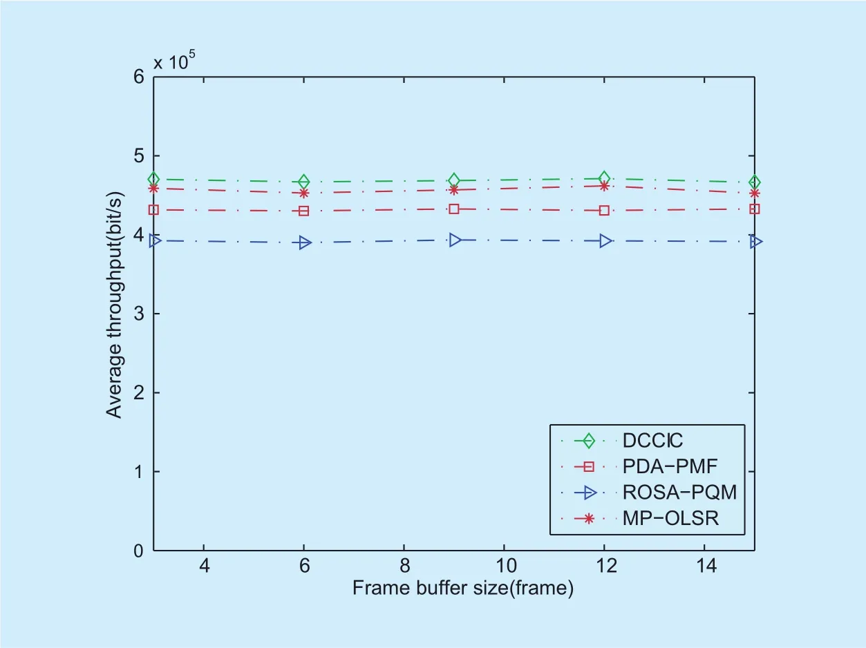
Fig. 3. Average throughput under different frame buffer size.
From figure 3, it can be seen that the average throughput of DCCIC is higher than that of PDA-PMF, ROSA-PQM and MP-OLSR.In figure 4, the average end-to-end delay of DCCIC is lower than that of other three com-pared algorithms. The reason is that DCCIC considers waiting time of the head-of-line packets in data queues in scheduling, and the packets with higher delay will be transmitted first. Figure 5 shows that the average playout time ratio of DCCIC is higher than that of PDA-PMF, ROSA-PQM and MP-OLSR.The reason is that DCCIC schedules packets considering the statuses of frame buffers, and the video sessions in danger of under flow can obtain transmission opportunity with higher priorities, which improves the video playout continuity. From figure 6, it can be seen that the average rebuffering times of DCCIC is the lowest in all four schemes. Figure 5 and figure 6 also show that the increase of frame buffer size can result in the increase of video playout continuity and QoE.
Figure 7, Figure 8 and figure 9 show the average packet loss rates of I frame, P frame and B frame, respectively. All these figures show that the average packet loss rates of I-frame,P-frame and B-frame of DCCIC are lower than those of other three algorithms. Special-ly, as DCCIC schedules packets according to waiting time of head-of-line packet of Q queues, this increases the scheduling priority of B-frame in DCCIC and reduces the average packet loss rate of B-frame.
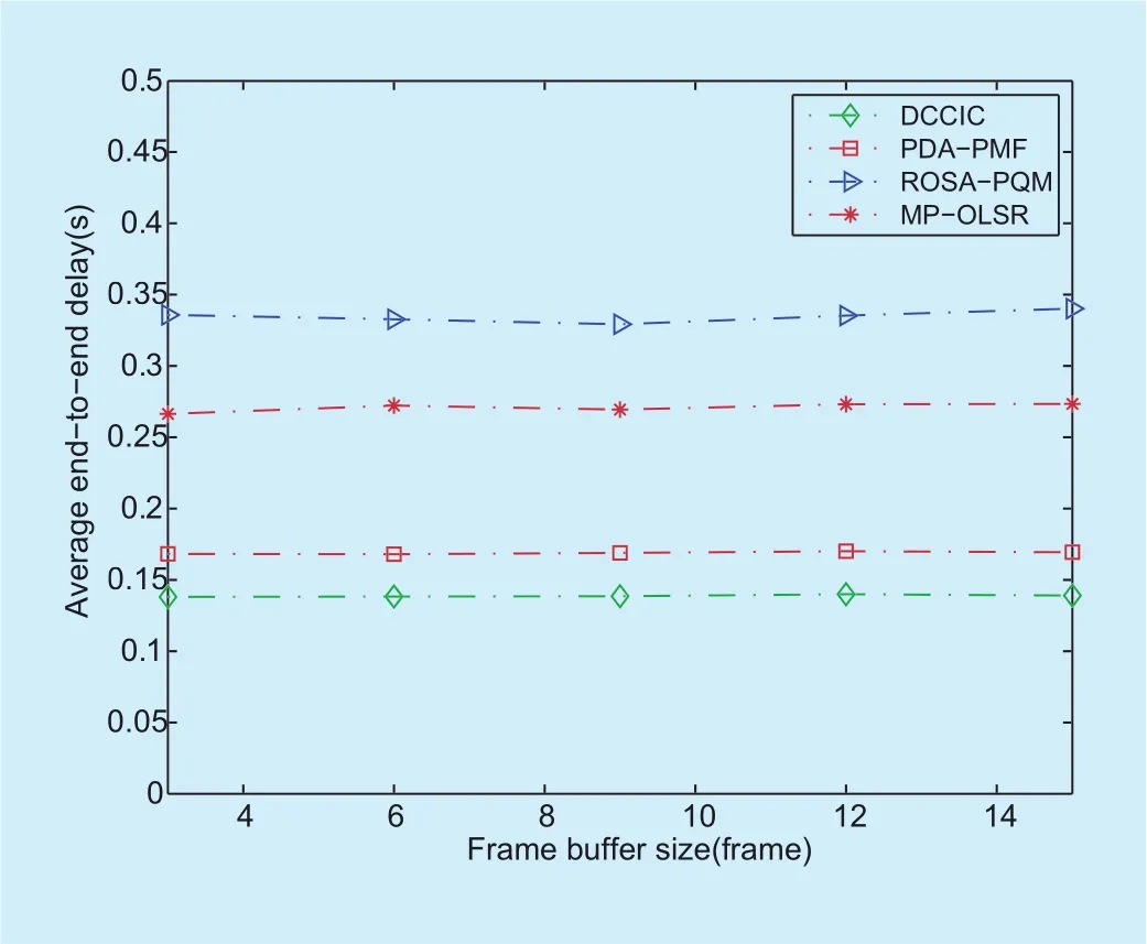
Fig. 4. Average end-to-end delay under different frame buffer size.
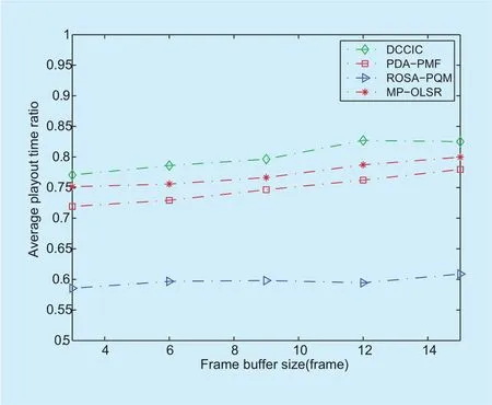
Fig. 5. Average playout time ratio under different frame buffer size .
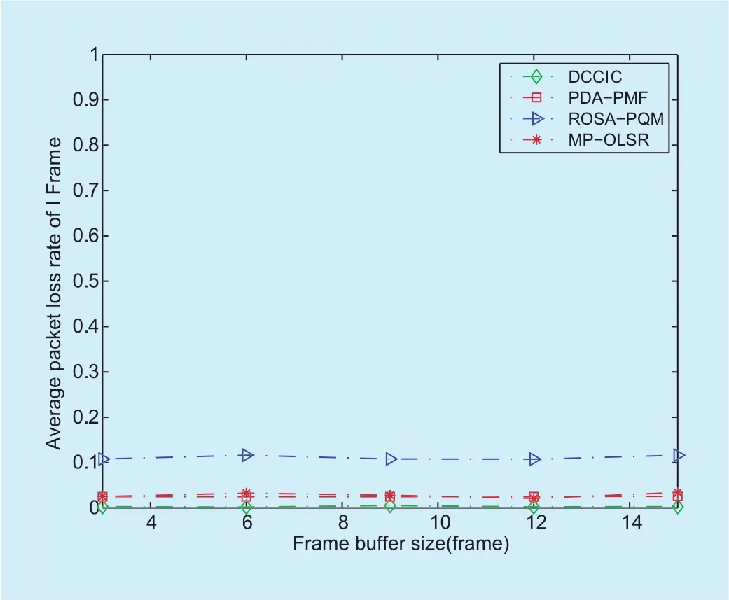
Fig. 7. Average packet loss rate of I-frame under different frame buffer size.
From figure 10 to figure 16, the frame buffer size is 6 frames.
From figure 10 to figure 13, it can be seen that, under different bandwidth of data channel, DCCIC performs better than the other three compared algorithms in the average throughput, the average end-to-end delay, the average playout time ratio and the average rebuffering times. As in the scheduling of DCCIC, the queues with high waiting time of head-of-line packets can access data channel first, the average end-to-end delay of DCCIC is reduced, and lower than that of PDA-PMF,ROSA-PQM and MP-OLSR. Through scheduling packets according to the virtual queue of frame buffer, the video playout continuity is increased. Then, the average playout time ratio of DCCIC is higher than that of the other three compared algorithms.
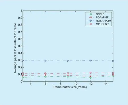
Fig. 8. Average packet loss rate of P-frame under different frame buffer size.
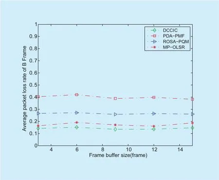
Fig. 9. Average packet loss rate of B-frame under different frame buffer size.
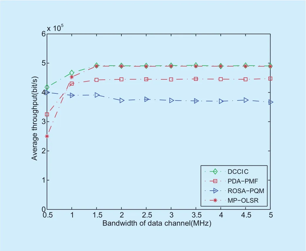
Fig. 10. Average throughput under different bandwidth of data channel.
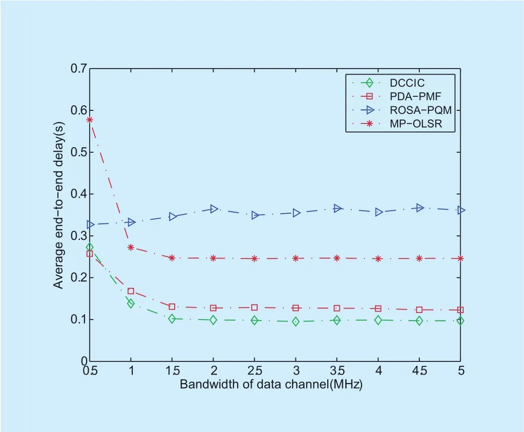
Fig. 11. Average end-to-end delay under different bandwidth of data channel.
When the bandwidth is higher than 1.5MHz, the performances of DCCIC, PDAPMF and MP-OLSR are close to steady. The reason is that the bandwidth of data channel is high enough, and the performances of these algorithms achieve the best performances they can achieve. Different from above three algorithms, with increase of bandwidth from 0.5MHz to 2MHz, performances of ROSA-PQM deteriorate. In ROSA-PQM, packets of different types of frame are organized into one queue, and the queues are scheduled for data transmission according to prioritized values, not queue lengths. As bandwidth increases, shorter queues with higher prioritized values will obtain more transmission opportunities, and this results in reduction of utilization rate of bandwidth of data channel, as well as performances of ROSA-PQM.
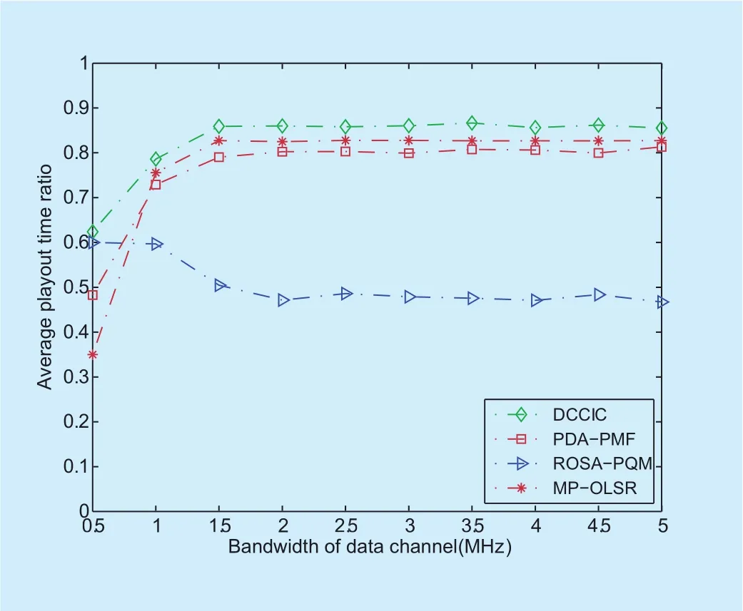
Fig. 12. Average playout time ratio under different bandwidth of data channel .
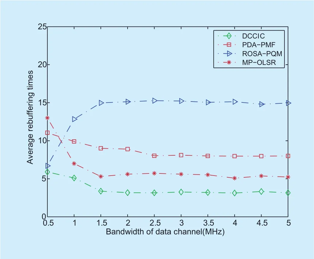
Fig. 13. Average rebuffering times under different bandwidth of data channel.
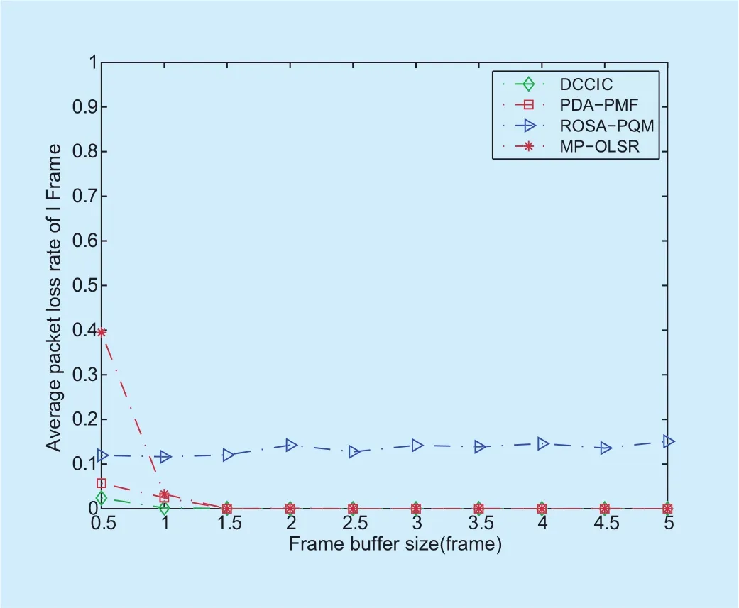
Fig. 14. Average packet loss rate of I-frame under different bandwidth of data channel
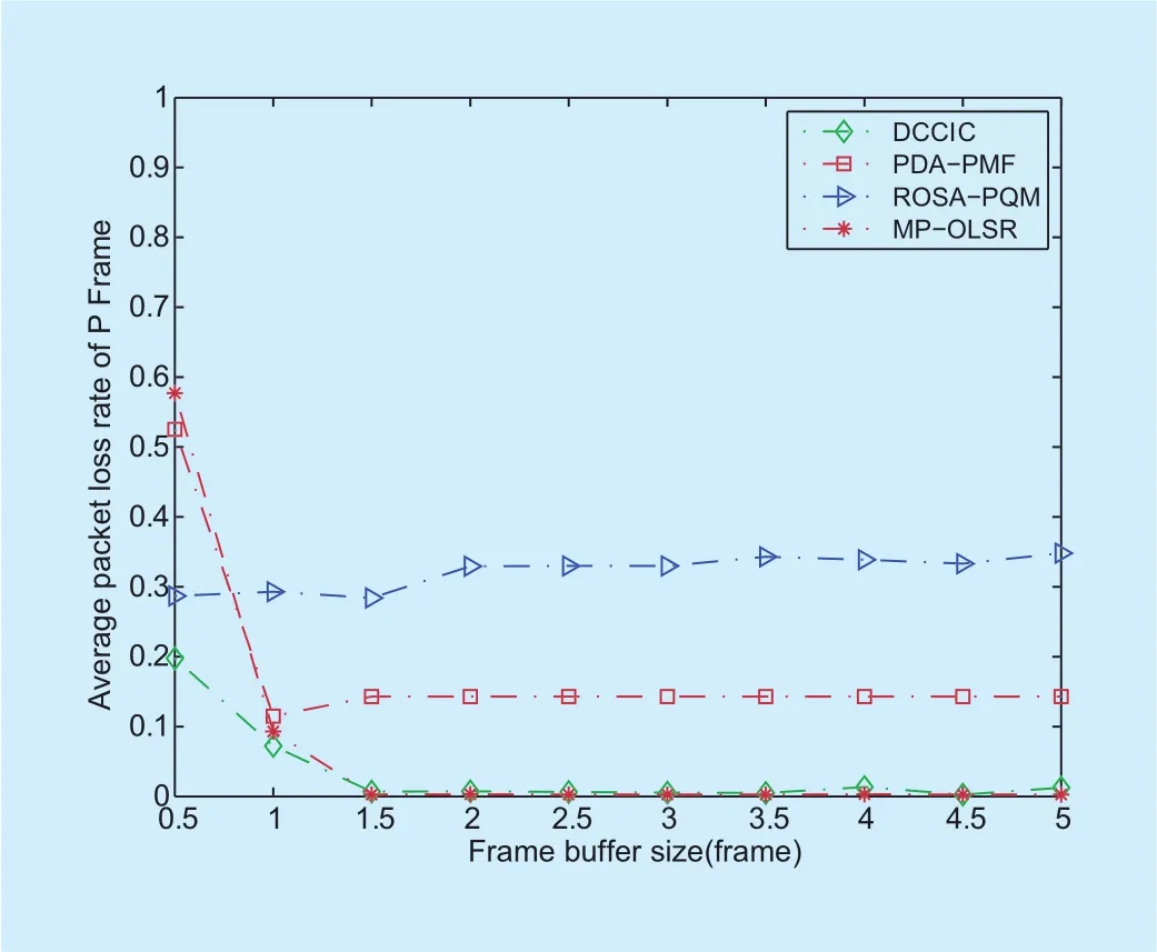
Fig. 15. Average packet loss rate of p frame under different bandwidth of data channel.
The average packet loss rates of I-frame,P-frame and B-frame under different bandwidth of data channel are shown in figure 14,Figure 15 and figure 16, respectively. In all figure 14 and figure 15, the average packet loss rates of I-frame and P-frame of DCCIC are close to zero, and lower than those of other three algorithms. The reason is that under DCCIC, packets are scheduled according to waiting time of head-of-line packet of Q queues,which improves the transmission fairness and reduces the average packet loss rate of packets. Fig 16 shows that DCCIC performs better than other algorithms on packet loss rate of B-frame, except that when bandwidth of data channel is 0.5MHz, the average packet loss rate of B-frame of DCCIC is higher than that of ROSA-PQM, which does not bring changes on the result of performance comparison.
Under the conditions that the bandwidth of data channel is 1MHz and frame buffer size is 6 frames, the average PSNR under DCCIC,PDA-PMF, ROSA-PQM and MP-OLSR are 25.57dB, 20.72dB, 19.68dB and 25.02dB,respectively. This implies that the quality of video under DCCIC is better than the qualities of video under other algorithms.
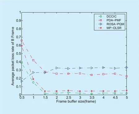
Fig. 16. Average packet loss rate of B-frame under different bandwidth of data channel.

Fig. 17. Original frame for No.7.

Fig. 18. Reconstructed frame with PDA-PMF scheme.
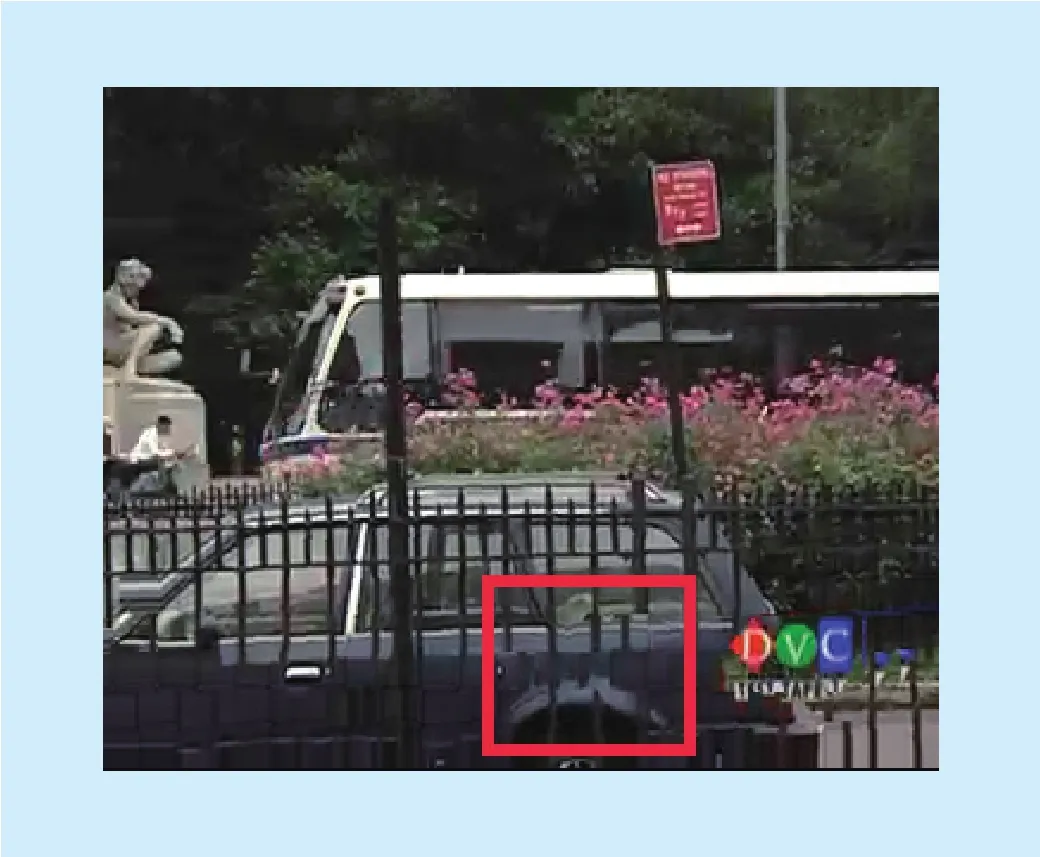
Fig. 19. Reconstructed frame with DCCIC scheme.
Therefore, DCCIC performs better than PDA-PMF, ROSA-PQM and MP-OLSR.
Figure 17 is the original No. 7 frame of the “bus.CIF”. Figure 18, Figure 19, Figure 20 and figure 21 are the reconstructed No. 7 frames at the destination node using PDAPMF, DCCIC, MP-OLSR and ROSA-PQM,respectively.
6.3 Performance comparison of gsm and distributed media access control scheme
In this section, performances of GSM and the distributed media access control scheme proposed in section 5.1 are compared. “Distributed Scheduling” means DCCIC using the proposed distributed scheme as the scheduling scheme. “GSM” means DCCIC using GSM scheme as the scheduling scheme.
From figure 22 to Fig 25, it can be seen that the performance of “GSM” is very close to that of “Distributed Scheduling”. This implies that effect of the proposed distributed media access control scheme can approach the effect of GMS scheme that has been mentioned in section 5.3.
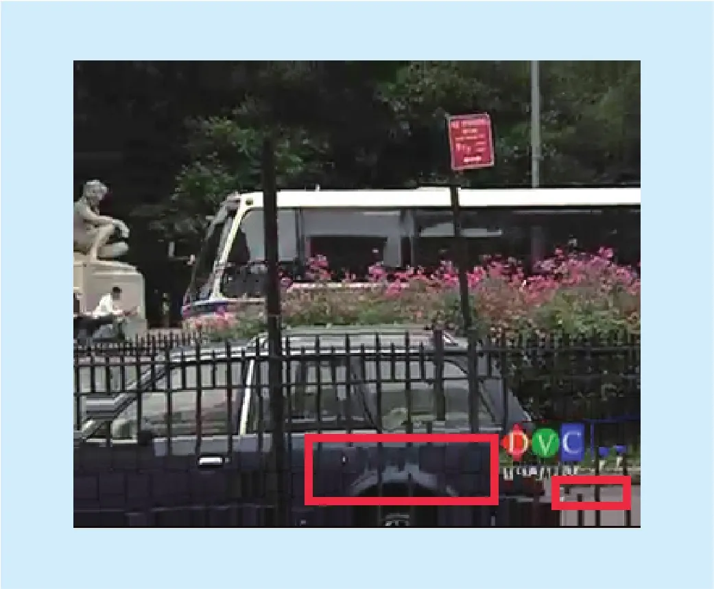
Fig. 20. Reconstructed frame with MP-OLSR scheme.

Fig. 21. Reconstructed frame with ROSA-PQM scheme.
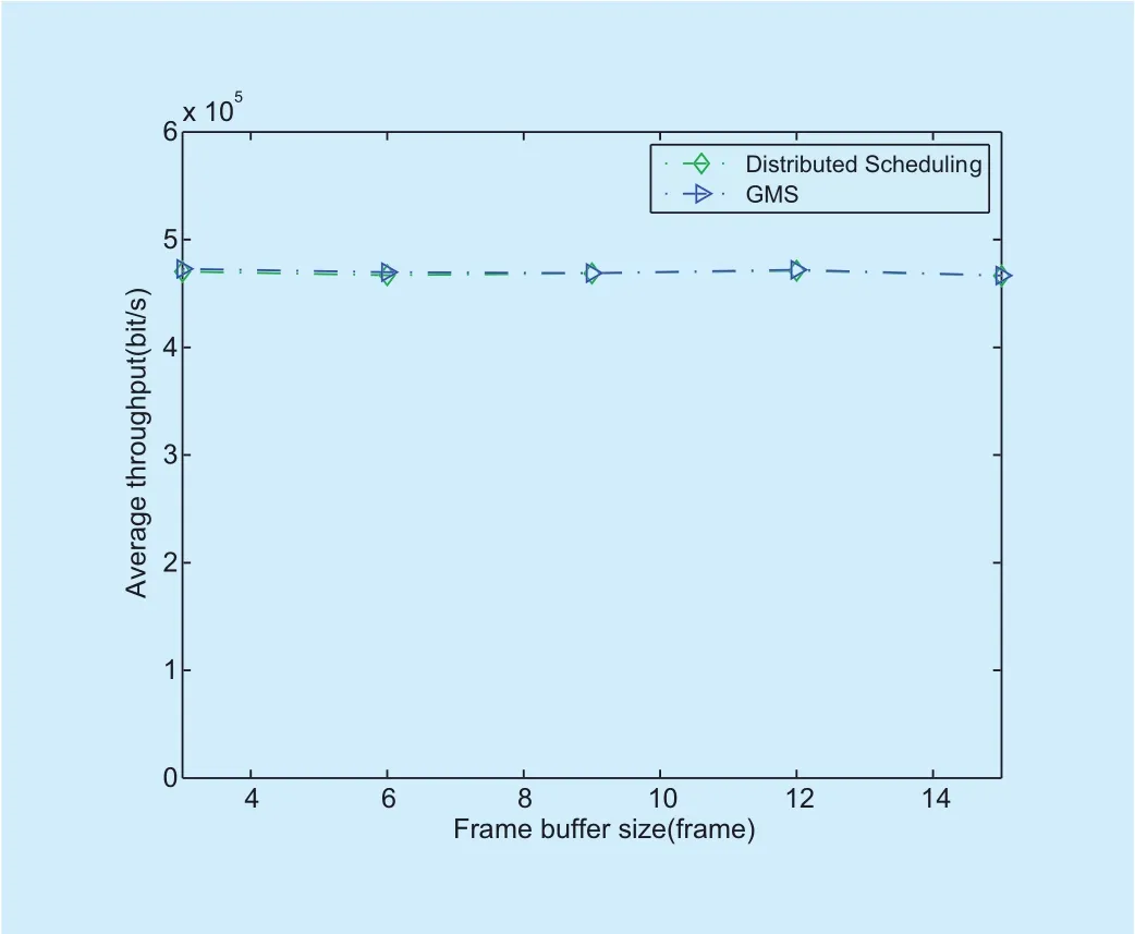
Fig. 22. Comparison of average throughput.
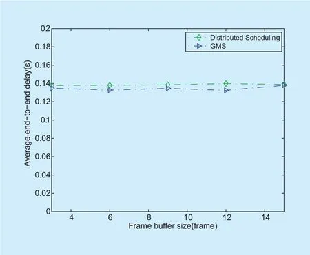
Fig. 23. Comparison of average end-to-end delay
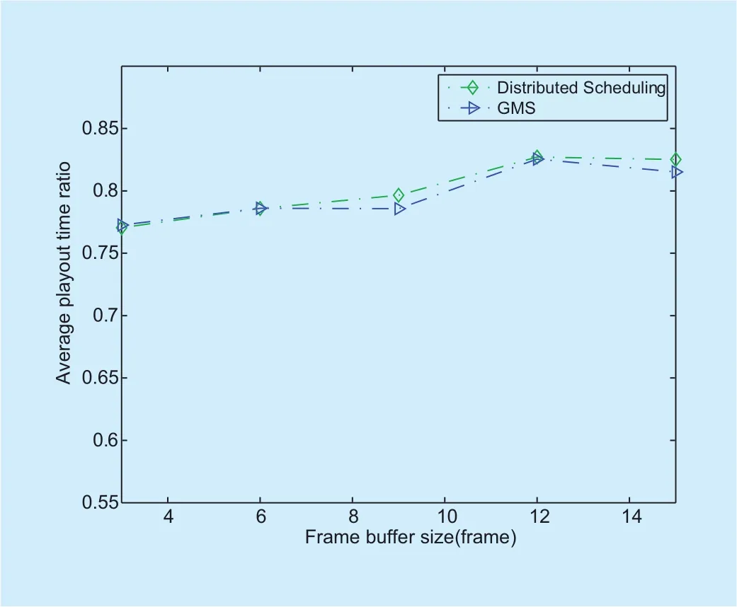
Fig. 24. Comparison of average playout time ratio
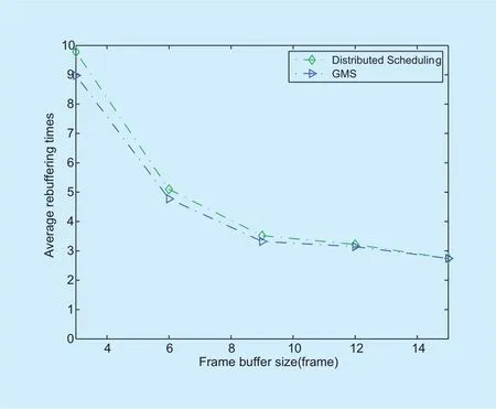
Fig. 25. Comparison of average rebuffering times.
VII. CONCLUSIONS
This paper proposed a delay-based cross-layer QoS scheme, which can improve the quality of video encoded/decoded using H.264/AVC in wireless Ad hoc networks. Packets belonging to I, P and B frames are allocated with different priorities according to their generated rates. The scheme increases video playout continuity through reducing frame buffer underflows by scheduling packets according to the statuses of frame buffers at the destination nodes. Average end-to-end delay of packets can be reduced, for waiting time of head-ofline packets of data queues are considered in scheduling. A distributed media access control scheme is designed to reduce computational complexity. A distributed power control algorithm is proposed to equalize transmission capacities of links. For future study, we plan to apply this policy in UAV (Unmanned Aerial Vehicle) networks.
- China Communications的其它文章
- DNN-Based Speech Enhancement Using Soft Audible Noise Masking for Wind Noise Reduction
- An MAC Layer Aware Pseudonym (MAP) Scheme for the Software De fined Internet of Vehicles
- Asymptotic Analysis for Low-Resolution Massive MIMO Systems with MMSE Receiver
- Golay Pair Aided Timing Synchronization Algorithm for Distributed MIMO-OFDM System
- Joint Non-Orthogonal Multiple Access (NOMA) &Walsh-Hadamard Transform: Enhancing the Receiver Performance
- 8-Weighted-Type Fractional Fourier Transform Based Three-Branch Transmission Method

