Crashworthiness assessment of thin-walled double bottom tanker: Influences of seabed to structural damage and damage-energy formulae for grounding damage calculations
Aditya Rio Praowo , Bo Cao , Jung Min Sohn , Dong Myung Bae
a Department of Mechanical Engineering, Universitas Sebelas Maret, Surakarta, Indonesia
b China Shipbuilding Industry Corporation Economic Research Center, Beijing, China
c Department of Naval Architecture and Marine Systems Engineering, Pukyong National University, Busan, South Korea
Abstract This work presents results of numerical analyses with focus on structural performance accounting for seabed topology, and investigation of energy formulae for application in calculation of grounding damage.Study in this work is divided into three stages, i.e.finite element method (FEM) verification using laboratory experiment, numerical calculation of ship grounding using FEM, and comparison of the FEM results with empirical formulae of damage-energy calculation.Fundamental formula of Minorsky is considered with other improvement expression, such as Woisin and Zhang.Investigation suggested that the recent-developed expression produces the closest estimation to the verified FEM results.On the other hand, fundamental formulae of Minorsky is the farthest compared to the FEM, which indicates constant value in the expression needs to be more specific as improved in the Woisin formula.
Keywords: Ship grounding; impact test; finite element method; damage-energy formula; crashworthiness criteria.
1.Introduction
Operations of industrial distribution are inseparable from human society and environment as growth of economy and urban development tend to depend on industrial condition.Oil market is a perfect example of the illustration since it is well known that the oil product is widely used in society, i.e.gasoline for motorcycle and car, kerosene for home indus- try, and avtur for aviation fuel.Dependence on oil product makes crude oil is widely transported (export-import activi- ties) to various countries from major offshore facilities across the globe.During this stage is conducted, at least three parts are directly involved, human as vessel/carrier crew, ship as vessel, and environment as medium where the vessel pass by to reach destination.Occurrence of maritime accident in transporting crude oil, including its derivative products, may significantly blow equilibrium of water ecosystems.Takes theSanchioil spill which approximately 50% to 70% of oil parti- cles remain in the ocean and mainly expand along the Ryukyu Island Chain and the region southeast of the Sanchi wreck [1] .Furthermore, more serious concern is addressed if criti- cal maritime zone, such as Arctic becomes subject of oil spill risk, which can be affecting land-based fauna as the oil may influence ice melting tendency, and reduce land area in Arctic territory.Holistic risk assessment to address various failures in this zone was introduced previously by Johannsdottir and Cook [2] who direct their attention to oil spill phenomena in the Arctic.More explicit example of huge impact due to oil spill was presented by theDeepwaterHorizon[3] andExxonValdez[4] which up to this day, recovery of ocean mammals and water ecosystems are still conducted.In the latter case, it is confirmed that several species, including whales, were extinct as effect of this oil spill.
Oil spill phenomena on maritime territory directs a series of statistical investigation to trace back the primary cause, which presented data in the latest Allianz report [5] suggested that accidental load in form of collision [6-8] , explosion [9-10] and grounding [11-14] are taking part in top ten cause list.In order to provide proper estimation of environmental casualties, reliable damage calculation were conducted by pi- oneer researchers to be fundamental data which can be used as a reference for further safety design [15-21] .However, in case of accident, rapid estimation is also needed besides detail calculation which require enormous effort.On the other hand, rapid estimation, such as using empirical expression for im- pact phenomena on thin-walled structures [22-24] , demands verification and comparison with other methods to ensure its reliability before it is applied for damage calculation.
Considering those facts related to the methodology and verification, this work aimed to calculate structural responses and crashworthiness criteria of a double hull tanker under ship grounding using a verified FE methodology.Effects of the external parameters, such as impact location and obstruction topology will be considered to observe structural responses in details for each scenario.Progressive failures were presented with bottom damage extent during ship grounding to provide a complete response estimations.Comparative discussion is presented as main subject in this work by considering cal- culated damage data using empirical approach and results of validated finite element analysis.
2.Understanding ship grounding
Accidental loads or so called impacts on marine structure have become a top priority due to its characteristic to cause remarkable disaster.Recent statistical evaluation since 2007 by Allianz [5] concluded that vessels’ wrecked/stranded (in- cluding grounding) are placed at the second place of top ten vessels loss causes.The ship grounding is found stable at this position, and it is only surpassed by vessels’ foundered for a decade (see Fig.1 ).Remarkable fatalities and high level risks for passenger, environment and carrier are also consid- ered to be important parameters to put ship grounding at this position.A series of oil spillage cases around the world, e.g.disaster of the Exxon Valdez in US territory and the Amoco Cadiz in Europe continent has provided solid evidence of ship grounding’s effect to both maritime and industrial casualties.
Based on its occurrence on ship, grounding is classified into two subcases, such as horizontal slide as referred byraking, and vertical penetration often mentioned asstranding.Raking occurs during powered-ship condition or when ship in straight motion during a voyage.Interaction with obstruction can be influenced by heavy fog and a navigational error in estimating topology in a sailing route.Other conditions are also possibly involved, such as bad weather and other catas- trophic event which affect dynamic motion of the ship.In these conditions, stranding is mostly taking place the pitch and heave due to wave movement and the bottom structure is laterally penetrated by rock or shoal.In terms of the oceanic obstruction, estimation of obstruction topology requires wide insight of seabed contour which its data is actually hard to be accessed.Most of the pioneer works use an assumption based on the damage of high profile Exxon Valdez accident in 1989 where a pinnacle of seabed opened a large part of ship bottom, for the seabed topology in grounding test and simulation.
Shipping safety, cargo protection and marine pollution are strictly linked which makes the environmental protection against major disasters, such as oil spill is complex.Numer- ous efforts to provide adequate protection can be classified into two parts.The first part is the active method which is conducted by ensuring shipping/voyage of ships can be well supported using good navigational instruments.Advance radar system, crew training and traffic control regulation are ex- amples of this part.The second part is the passive method which is presented by developing design crashworthy of ma- rine structures.Famous example of this method is initially announced by applying double hull systems since Oil Pollu- tion Act 1990 (OPA 90).As fast countermeasure of the Exxon Valdez’s oil spill due to a grounding phenomenon, double hull system on dangerous-cargo ships is introduced, especially to reduce the amount of oil spill.By applying this system to structures, ship will have two inner parts which protect the cargo during impact, namely double side shell and double bottom.The main idea of this system is if ship encounters collision or grounding, the inner shells in side and bottom structures ( Fig.2 a) of the double hull are still intact to reduce or even avoid of oil spillage after ship experiences the impact.Meanwhile, the conventional single hull ( Fig.2 b) will unleash remarkable amount of oil when the outer shell is breached by any obstructions.In this situation, chain disastrous events are highly taking place, such as stability loss, reduction longitu- dinal strength, structural collapse, which lead to life loss of crew and foundered or ship sinking.
3.Failure of the simplified ship hull
3.1.Experiment description
The references of the test and material details were taken based on a series of a resistance experiment of stiffened plate as the simplified version of ship structure [25 , 26] .The plate represented hull shell, and the stiffener was arranged as frame on the plate.The specimen in this experiment was described as a 1:3 scale model of the medium sized tanker.The specimen was manufactured to consist of three compo- nents, plate, stiffener and hollow frame.The sizes were given 720 × 1200 × 5 mm for the plate, 120 × 6 mm for the stiff- ener and 300 × 200 × 12.5 mm for the frame.Material prop- erties of the specimen’s components are shown in Table 1 .It was assumed that the hull damage occurred due to grounding action which a ship was set to settle vertically on a rock.This situation was defined in FE calculation by forcing anindenterto a depth of approximately 2500 mm into the center of the specimen.The load was assumed as the vertical displacement of the indenter with velocity 0.6 m/s.It was noted that when the speed of the applied load was slower than 2 m/s [27] or 10 m/s [28] , the inertia effect is insignificant Fig.9 , Table 2 .
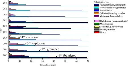
Figure 1.Summary of the ship loss due to accidental and non-accidental causes over the last decade.
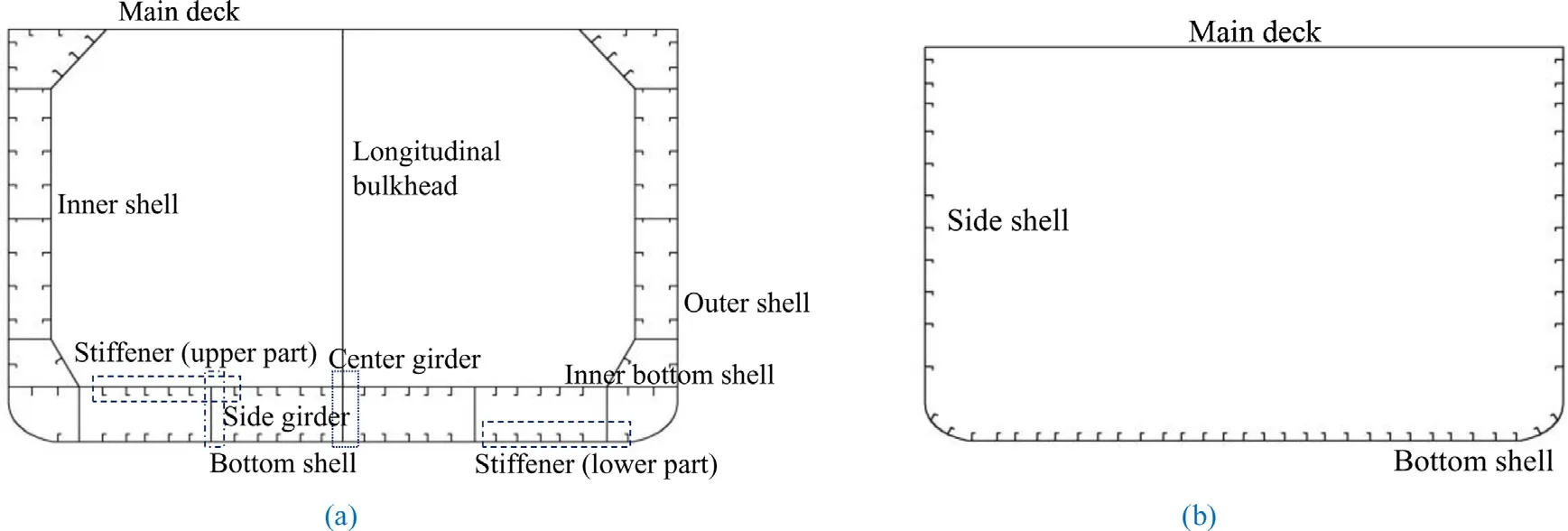
Figure 2.Illustrations of the hull design for ship structures: (a) advance double hull and (b) conventional single hull.

Table 1 Material properties for numerical simulation based on the penetration test [25 , 26] .

Table 2 Properties of the material models in FE simulation: double bottom structures.
The penetration of the stiffened plate would take place be- tween two stiffeners, while the hollow frame was assumed to be fully restricted for axial and rotational movements.The mesh sizes were determined based on element-to-thickness (ELT) ratio in range 5-10 as per recommended of pioneer works in impact analysis [29 , 30] .Illustrations of test spec- imen and process from both actual and virtual experiments are shown in Figs.3 and 4 , consecutively.During FE exper- iment, the indenter was initially located on the upper side of the specimen.The indenter was applied by the determined velocity (in the actual test) to move on negativez-axiswhen experiment was started.To avoid hourglass mode and shear- locking phenomenon, the specimen was built by shell element with shell formulation fully integrated Belytschko-Tsay.Con- tact was modelled as interaction between the indenter to the plate and stiffener, which the friction coefficient was assumed to be 0.3 as taken from Coulomb friction coefficient.
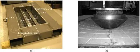
Figure 3.The testing specimen and penetration process: (a) and (b) show stiffened plate and loaded specimen [25] ,

Figure 4.The testing specimen and penetration process: (a) and (b) illustrate lower and upper view of the finite element models.
3.2.Results
Results of the present simulation was compared with ex- perimental test conclusion of Alsos and Amdahl [25] in terms of the resultant force during the indenter impact on the stiff- ened plate.Trend-line of the resultant force ( Fig.5 ) indicated that the laboratory test and numerical simulation showed good correlation, especially in displacement range 0 – 125 mm or until fracture on the specimen.After fracture took place ap- proximately between 125 – 150 mm, the force experienced quite significant reduction.It was found that the most similar in terms of the force tendency, was achieved with the mesh size 50 mm until displacement 125 mm.The mesh sizes 35-40 mm also produced similar results, even though displacement during fracture was slightly differ compared to the test with percentage less than 17% (test occurred in 125 mm, while current study in 150 mm).In other observational view, over- all trend line of the mesh sizes 25 and 30 mm was explic- itly similar to the actual test, which produced slight higher force than other sizes at displacement 125 mm but immedi- ate reduction at 150 mm.Based on these results, it could be concluded that the mesh sizes within the recommended ELT ratio range managed to produce similar results with the lab- oratory test and previous numerical simulation.The positive achievements in the benchmark analysis also indicated that the applied methodology is successfully verified and can be used for ship grounding analysis in further section.
4.Grounding analysis
4.1.Ship structures and selected material
Structure model in this work refer to a 144 m chemical tanker which idealization is addressed on the bottom struc- tures.Local members, i.e.stiffener, bottom plate, inner bottom plate, bilge plate, transverse floor, and girders are modelled using thin-walled concept with the 4-node shell element was chosen to arrange the structure in finite element (FE) analysis by explicit codes ANSYS-LS DYNA [31] .Fully integrated version of shell formulation introduced by Belytschko-Tsay was embedded to the bottom structure in order to avoid hour- glass and shear locking mode.The structure was implemented by a deformable so that it will experience structural damage under ship grounding, which the plastic-kinematic model is selected to define the deformable structure.

Figure 5.Results of the present study and its comparison with the actual test by Alsos and Amdahl [25] .

Table 3 Proposed constant value to estimate failure strain accounting for mesh size [32] .
During interaction with oceanic obstruction, heavy damage is expected on the structure, such as shell rupture and girder crushing.In this case, definition of structural failure needs to be properly explained, which failure was described as a con- dition of any local members (plate, stiffener, and girder) sur- passed their ultimate strain, and experienced excessive plastic due to impact load from grounding phenomenon.Besides the ultimate strain, mesh configuration was considered as critical factors in impact analysis as it affects geometry the struc- tural deformation.Recommended criterion oftheDetNorskeVeritas-GermanischerLloyd[32] which was used in the benchmark studies will be applied according to regulation in Table 3 , to discretise the structural model.
As interaction of the structure and obstruction was ex- pected in grounding analysis, it was necessary to consider friction value as part of contact properties.Generally, this value is taken according to Coulomb friction coefficient in the range 0.2-0.4 which are previously adopted by Simonsen [33] .Variation in the coefficient implementation may occur considering the condition of the underwater hull surface con- ditions, especially bottom and bilge plates.In many cases, the plate surface becomes slippery due spilled oil and marine plant.Assumption of the surface roughness as influenced by manufacturing process, can also be affecting factors.

Table 4 Properties of the material models in FE simulation: oceanic obstructions.
4.2.Seabed topology and applied material
This entity of seabed topology would be modelled as a solid-rigid material to approach real case of hard-grounding situation.Based on this assumption, the structure was de- signed to absorb impact energy and experienced structural deformation process.Summary of material models for this seabed is presented in Table 4 which referred to mineral com- pound in oceanic seismology formation.The seabed would be determined as the obstruction which is varied into two topol- ogy types.Geometry of contact surface on the obstruction is considered as an important factor in experienced damage on ship.Therefore, two obstructions with different geome- try and configuration than the previous conical obstruction are designed and denoted byrockandshoal(see Fig.6 a- b consecutively).ThePyroxeneis set to be embedded on these obstructions and deployed in comparative study to as- sess structural behaviour against different obstruction under hard grounding scenario.
4.3.Detail of grounding scenarios
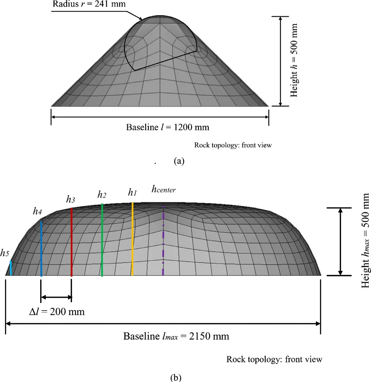
Figure 6.Geometry and configuration of the selected oceanic obstructions: (a) rock and (b) shoal.
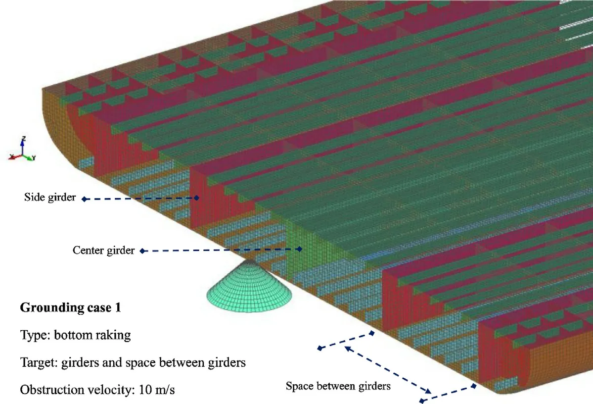
Figure 7.Grounding scenario for the first case, bottom raking.
The initial grounding analysis was addressed to observe structural behaviour of the double bottom under ship ground- ing, specifically bottom raking.As illustrated in Fig.7 , the bottom raking is designed to be experienced by three targets, including center girder, side girder and space between gird- ers.In these scenarios, the conical obstruction was placed in-line to the ship model and applied with uniform velocity 10 m/s.Under bottom raking scenario as described in prior raking analysis, the rockandshoaltopology as described in Fig.6 a-b were deployed to act as the obstructions.In this comparative study, grounding scenarios were performed by a displacement which controlled behaviour of the internal me- chanics.The structure was applied by steel AISI 1030 and fully clamped on the inner bottom and bottom shells to re- strain its movement during penetration by the obstruction.The raking process was defined as very short loading which the limit of the FE simulation was to betsim.= 0.5 s.Overall dis- cussions to observe all conducted scenarios, including raking- stranding and rock-shoal cases were presented as a summary of this study.Tendency of crashworthiness criteria, assessment on damage mechanism and verification of the finite element (FE) results using empirical formula were presented to eval- uate the accuracy of each method.
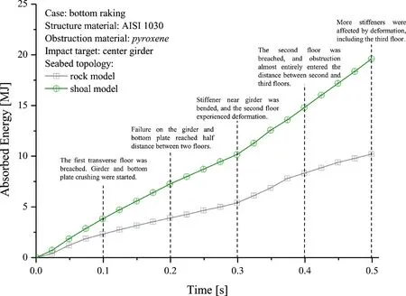
Figure 8.Absorbed energy of the rock and shoal models during the raking case.
5.Results and discussions
5.1.Effect of the obstruction geometry on the bottom structure
Assessment of structural crashworthiness is continued by conducting a study addressed to observe effect of obstruction geometry to structural damage.In order to vary structural responses, time simulation was set to betsim.= 0.50 s, carbon steel material 1030 was applied on the double bottom, and the obstruction would be implemented by thepyroxene.Raking scenario was chosen to be performed in current comparative study to produce a calculated prediction regarding structural responses against a variety of obstructions, i.e.rockandshoal.
In terms of the absorbed energy ( Fig.8 ), the shoal obstruc- tion produced higher level than the rock during raking phe- nomenon, which an approximation could be concluded that it was twice higher than the rock.Minor increment in terms of the absorbed energy after deformation on the second trans- verse floor began (tsim.= 0.30 s) indicated that the rock model had lower magnitude than the shoal.This behaviour was veri- fied by the crushing force ( Fig.9 which steep angular distance on the impact surface for the shoal model produced higher force in both early contact (tsim.= 0 – 0.05 s) and after de- formation on the second floor was started (tsim.= 0.3 s).In terms of structural damages, overall progressive failure on the double bottom was quantified in several stages: 1.Crushing of the first floor began, and it was followed by girder and bot- tom plate; 2.The tearing failures for girder and plate reached half distance of two floors in approximately (tsim.= 0.2 s); 3.Stiffener in girder was bent in crushing process while the second floor experienced initial deformation; 4.The second floor was breached, and obstruction almost entirely entered the next compartment (between the second and third floors); 5.More stiffeners were affected by deformation, and the third floor already experienced deformation.
Overall penetration by the shoal also indicated larger dam- age tendency of this topology than the rock obstruction.De- tails of seabed topology indicated that contributions of base- line lengthlwas found significant in expanding damage range on the double bottom.As rock and shoal obstructions were fully breached the bottom structure, it could be predicted that the occurred damage width for both obstructions was similar and tended to be the same with the maximum diameter of the selected obstruction in the interaction point.Larger size of the shoal length indicated wider diameter, which further- more it was evidenced that larger damage extent caused by the seabed shoal than the idealised rock (see explanation of contact point in [34] ).More specific observation on topolog- ical aspect of the obstructions concluded that combination of the formed angular distance between baseline and obstruc- tion increment also affected the damage pattern on the de- formable structure.Steeper geometry would be cleanly wiped structural component on the double bottom ( Fig.10 ), espe- cially the longitudinal girder which hold critical role in resist- ing penetration during the raking case.This crushing mode was directly contributed to the observed criteria and structural responses.
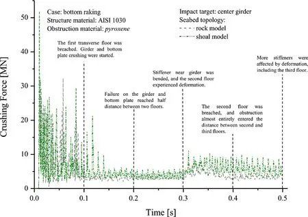
Figure 9.Crushing force of the rock and shoal model in the raking case.
5.2.Approach comparison and overall discussions of grounding phenomena
Development of calculation method in impact analysis and engineering provides several approaches to assess struc- tural response.Early introduction was already addressed that collaboration of these methods would provide better under- standing in crashworthiness results.The benchmark in this study was conducted using a combination of laboratory test- ing data and finite element (FE) simulation.The verified setting and configuration for the ship grounding analysis is obtained in the prior study.In this section, comparison of this work, including the first part of grounding assessment [34] , was presented by adopting empirical approach to evalu- ate commonly used method in impact.Empirical approaches ( Eqs.1 - 4 ) were used to obtain the absorbed energy in the end of grounding.Eq.3 was taken based on summary of Mi- norsky analyses [22] on twenty six collision cases of ship accident.This formula was refined by Woisin [23] who in- troduced low-energy collision equation by included effect of height of broken member and component thickness.In the early 2000s, several mathematical forms were developed by Zhang [24] to asses absorbed energy based on the damage mode.These formulas have the same fundamental concept which the energy is equally perpendicular with the amount of damaged parts of the involved structures/entities.

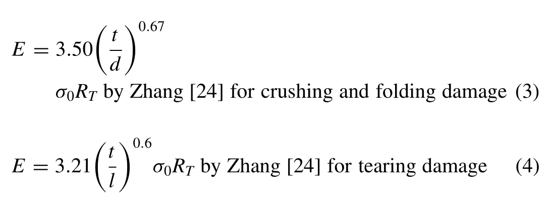
whereE= the absorbed energy;RT= the volume of de- stroyed material;h= the height of broken or heavily de- formed longitudinal members;ts= the thickness of the mem- bers;σ0= the flow stress of the material;t= the average thickness of the crushed plate;d= average width of the plates in the crushed cross-section; andl= critical tearing length.
Calculation results by the empirical formula ( Table 5 ) showed correlation with the FE simulation in this work, in- cluding the first part of this work [34] which compared signif- icance of raking and stranding to structural crashworthiness.The most similar was presented by the Woisin and Zhang for- mulas, consecutively.This tendency was successfully verified that the developed formula successfully increased accuracy of the empirical calculations in predicting the energy crite- rion based on damage extent.Confirmation of the Minorsky formula was also acquired based on these results which this formula only suitable for high energy impact.If larger size of the obstruction is considered in future work, the FE en- ergy will be approximately match with Minorsky formula.Compatibility of the collision formula was evidenced by the positive results during comparison was addressed for raking and stranding cases.Including the extended study for variety of the obstruction topology ( Table 6 ), the Woisin and Zhang formulas were concluded well enough to predict the absorbed energy during various cases of ship grounding.
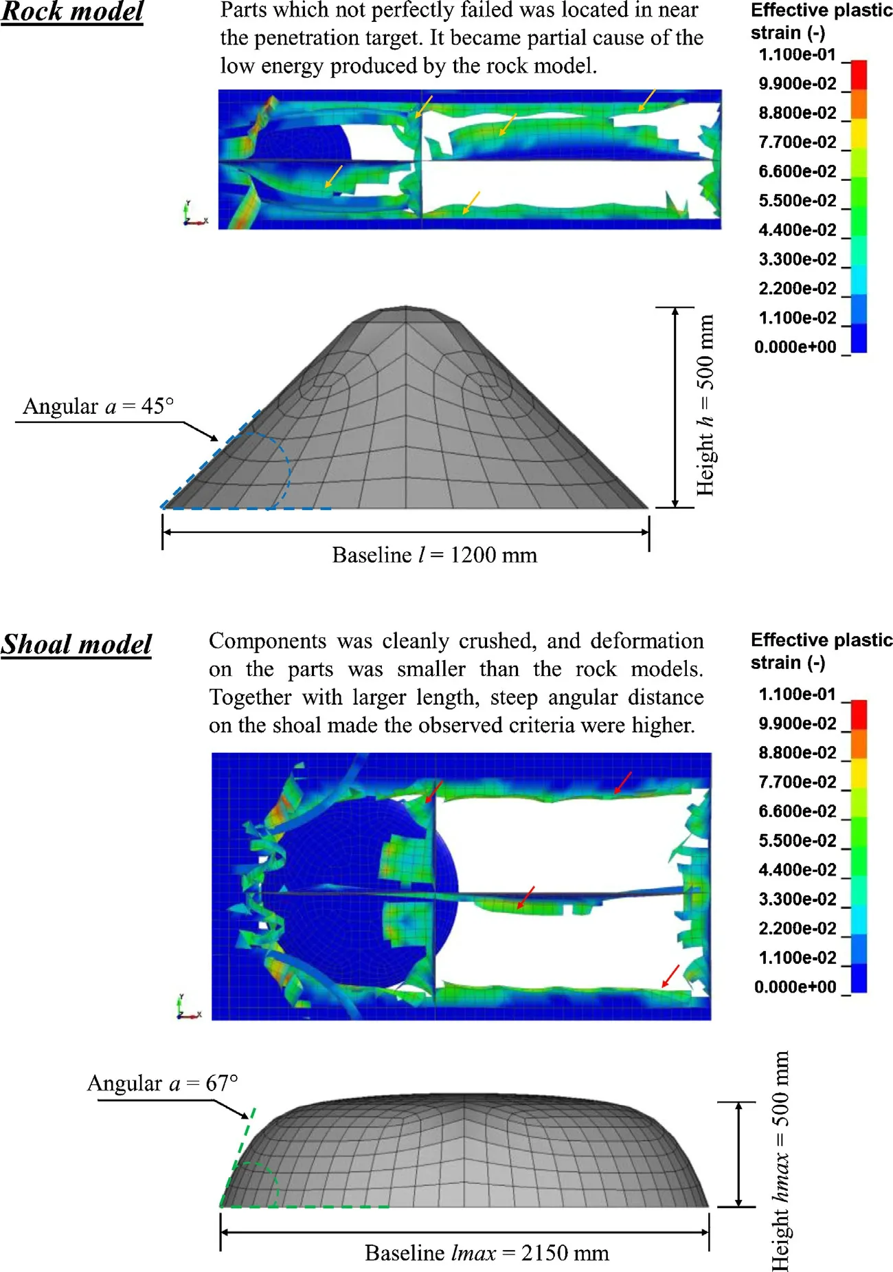
Figure 10.Configuration of obstruction model and caused damage pattern on the same target.

Table 5 Summary energy calculation by the empirical formula.Developed formulas by Woisin [23] and Zhang [24] presented better similarity with the current FE analysis.

Table 6 Calculation of the absorbed energy for the rock and shoal grounding.

Table 7 Structural response and damage extent for the raking and stranding scenarios.
Structural response and damage extent of the bottom struc- ture after several scenarios ( Table 7 ) indicated that the crash- worthiness criteria were correlated with each other.In case of high absorbed energy, intense critical (by von Mises ap- proach) and shear stresses were produced by the structure.For example, previous discussion in the raking case concluded the highest resistance was produced by the center girder among all targets in this case.This statement was validated by the stress level of the side girder and space between girders, which its intensity was lesser than the center girder.Same tendency was found on the stranding case, which the most in- tense stress was observed on the girder-floor intersection.On the other hand, damage extent for each grounding case was found different.It was influenced by structural arrangement on the target and applied penetration mode of the obstruction.For example, in the raking case during the side girder was determined as the target, the center girder did not get any significant effect.Response of the other structure members, such as stiffener also notable as it was torn during obstruc- tion hit the center girder, and it was crushed in the space between girders.In the girder scenario, the stiffener initially folded due to penetration by the rock.However, since the stiff- ener was arranged narrower near the center girder, they were torn and several parts of them were crushed by the obstruc- tion.Meanwhile, on surrounding the side girder, the stiffener space was wider which made this part was folded.Most of the stiffener were crushed in the grounding to space between girders.There was no girders in this target, which practically the stiffener became the only longitudinal member resisted the obstruction.
More similar tendency was presented by the stranding case for the damage extent after penetration, such as girder was crushed, stiffener was torn, as well as bottom and inner bot- tom plates were breached.This tendency was influenced by damage range of each scenario in grounding.The bottom rak- ing had wider range as it moved in longitudinal direction.This process alone would allow the obstruction to interact with numbers of structural component, and made the varia- tions in damage extent had high probability to occur as pre- sented in this work.The stranding case on the other hand, had very limited crushing scope, i.e.it was only allowed to move in space between the bottom and inner bottom shells.Observation in terms of damage extent also emerged a con- clusion that the tank space was more prone subjected to ship stranding compared to raking scenario.Verification was pre- sented in Fig.11 that the bottom shell was not giving high resistance in ship stranding as provided during raking.This phenomenon occurred as the bottom shell in raking was ac- tually strengthened by the stiffener and floor, while in strand- ing, only stiffener acted as longitudinal member on the tank space.
In case of the comparison between the rock and shoal ge- ometries ( Table 8 ), steep angular distance was found more capable to crush the structural component on the bottom struc- ture.This statement was taken as two longitudinal members, namely center girder and stiffener were crushed by the ob- struction in raking scenario to the center girder.Based on this tendency, it can be predicted that the worst damage on the bottom structure in raking scenario will occur during the ob- struction possesses striking angle 90 ° on its contact surface.The damage extent of the interacted parts with this obstruc- tion type can be concluded in crushed state, which in this case, massive oil spillage from double bottom tank will be unavoidable.

Table 8 Comparison of the structural response and damage extent for the rock and shoal geometries.
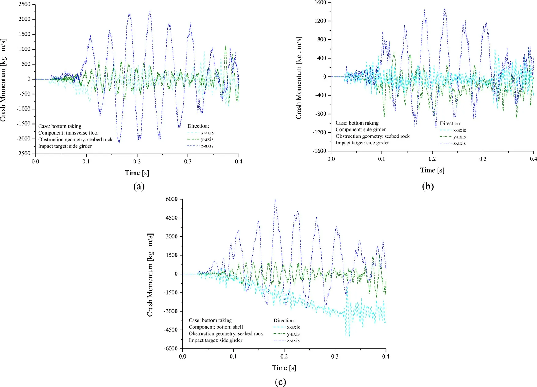
Figure 12.Crash momentum for component parts in the raking scenario: (a) floor, (b) girder and (c) shell.
Information of the crash momentum as a crashworthiness criterion on the structural impact was considered necessary to be observed.Crash momentum is the criterion which re- flects transfer-momentum behaviour from the obstruction to the structure during impact.In Newtonian mechanics, mo- mentum is the product of mass and velocity of an object.It is a three-dimensional vector quantity, possessing magnitude and direction.This criterion is useful to observe critical di- rection which is experienced by a structural member in its interaction with the obstruction.As presented in Figs.12 and 13 for the raking and stranding scenarios, grounding caused massive impact on the members in the z-axis (according to the Cartesian coordinate system) regardless the penetration mode.Even though the raking happened in longitudinal di- rection, critical direction was also shown in the vertical axis, same with the stranding case.The momentum concluded that during the structure crushing, the selected parts, namely floor, girder and shell was deformed in the z-axis.They finally ex- perienced rupture after ultimate strain limit was surpassed.This results also confirmed the findings of Hu et al.[35] re- garding illustration of the plastic rolling process, which the plate was distorted in vertical axis due to advance movement of the indenter during ship grounding.
Furthermore, crash momentum was satisfyingly validating other criterion, namely absorbed energy where the bottom plate was found received high level of momentum during im- pact which leads to experience major structural damage and high amount of the absorbed energy.Comparison with ana- lytical theory by Simonsen [7] which stated that the lowest part of the ship structure would experience the most damage in grounding, was successfully confirmed by the crashwor- thiness criteria presented in this study.It is recommended to expand the observation to impact assessment of structural re- sponses and criteria for ships under extreme environmental conditions, such as the Northern Sea route.Application of the present point of view and discussion on the underwater impact is encouraged to be sustainably continued, especially using FE analysis.Previous work in this field presented by Woelke [36] and Storheim [37] can be robust literature for research in impact assessment using numerical method.Re- lated research of polar region and accidental load by Cao et al.[38] , and design methodology to prevent further environmen- tal damage due to oil spillage by Tan et al.[39] are proposed to be reviewed in order to provide fundamental concept and detail insight for potential challenge in the fields of marine structures and impact engineering.
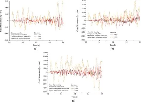
Figure 13.Crash momentum for component parts in the stranding scenario: (a) floor, (b) girder and (c) shell.
6.Conclusions
This work presented a series of crashworthiness assess- ment on several grounding cases.An actual laboratory test was considered as a benchmark study in order to obtain vali- dated setting and configuration for FE analysis.It was found that larger mesh sizes tend to experienced delay the onset of material failure which leads to higher peak force.This ten- dency might be influenced by strain averaging over a large element area.Based on this result, it could be concluded that if the geometry reference was a scaled version of the large structure, ELT ratio was suggested to be applied for analysis.Main study was conducted to observe the behaviour of the double bottom structure against impact load.Extended study on the obstruction topology concluded that the steeper an- gular distance and baseline length were the main parameter which directly contributed to structural damage.The shoal model emerged as worse obstruction than the rock in raking analyses.
It was realized that evaluation on crashworthiness calcu- lation approach was necessary to keep the method in check related to its reliability.Besides laboratory test, empirical cal- culation was also considered in this study.Results concluded that the present work was match with the mathematical ex- pression for the low-energy phenomenon.Confirmation for the Minorsky formula to be applied for high-energy collision and grounding was well-evidenced by comparison with devel- oped formulas by Woisin and Zhang.Based on the results, it was also obtained that these two formulas presented better ac- curacy for the absorbed energy prediction than the Minorsky formula for the designated grounding scenarios.Verification of the structural crashworthiness was also conducted by pre- senting crash momentum for the raking and stranding cases, consecutively.Tendency indicated that the structural compo- nent was mostly damaged in the vertical direction.Further- more, it was found that the bottom shell as the lowest com- ponent experienced the most damage in grounding according to the evaluation of energy, force, momentum and damage extent criteria.This result was satisfyingly match with the pi- oneer analytical theory which described that the lowest part on ship would experience major damage in grounding.Addi- tionally, it is important to note that the method not referred/ specifies cumulative probability density functions for colli- sion energy with which the struck ship will have to cope in a collision.
 Journal of Ocean Engineering and Science2020年4期
- Journal of Ocean Engineering and Science的其它文章
- Developing a predictive maintenance model for vessel machinery
- Towards an improved intuitive interface for Remotely Operated Vehicles
- A computationally efficient method for identification of steady state in time series data from ship monitoring
- A numerical simulation case study of the coastal currents and upwelling in the western Persian Gulf
- Analysis of Lakes pollution model with Mittag-Leffler kernel
- Steady and unsteady flow simulation with SRH-2D
