
Proactive Connection Recovery Strategy with Recovery Time Constraint for Survivable Elastic Optical Networks
2021-03-27 08:01:01DineshKumarRajivKumarNeeruSharma
China Communications 2021年9期
Dinesh Kumar,Rajiv Kumar,Neeru Sharma
Department of Electronics&Communication Engineering,Jaypee University of Information Technology Waknaghat,Solan(HP)India
Abstract: This paper presents a halfway signaling exchange shared path protection (HSE-SPP) on the backup route for a fast connection recovery strategy.In the proposed HSE-SPP,a pre-assigned intermediate node on the backup route is chosen for signaling exchange.When connection fails,source and destination nodes simultaneously generate backup connection setup messages to the pre-assigned intermediate node on the reserved backup route.At the intermediate node,signaling process occurs,and acknowledgment is generated for data transmission to the respective end nodes.Consequently,connection recovery time by applying HSE-SPP becomes very low.Simulations are performed for network parameters and results are verified with existing strategies.The average recovery time (RT),bandwidth blocking probability (BBP),bandwidth provisioning ratio (BPR),and resource overbuild (RO) ratio of HSE-SPP for ARPANET is 13.54ms,0.18,3.02,0.55,and for dedicated path protection (DPP) are 13.20ms,0.56,6.30,3.75 and for shared path protection (SPP) 22.19ms,0.22,3.23,0.70 respectively.Similarly,average RT,BBP,BPR and RO of HSE-SPP for COST239 are 8.33ms,0.04,1.64,0.26,and for DPP 4.23,0.47,3.50,2.04,and for SPP 11.81,0.08,1.66,0.27 respectively.Hence,results of the proposed strategy are better in terms of RT,BBP,BPR,and RO ratio.
Keywords:routing and spectrum assignment;halfway signaling exchange-shared path protection (HSESPP); dedicated path protection; bandwidth blocking probability(BBP)
I.INTRODUCTION
In the last few years due to the huge technological revolution,the number of internet users increases[1]which results in the accumulation of internet traffic proportionally.The use of the internet drastically changes the lifestyle of society,most of the internet users access different multimedia services such as video conferencing,online games,marketing,3D imaging,5G,and cloud applications.These services demand a very high data rate.In order to meet such a high data rate,the optical network is the first choice of the service provider due to huge bandwidth availability.To accomplish future internet user’s demand,transmission technologies require a more flexible and efficient utilization of network resources.
In a traditional optical network,the spectrum is subdivided into fixed wavelength slots by using a wavelength division multiplexer (WDM)[2,3].A wavelength has a capacity of 40Gbps or 100Gbps[4].The entire spectrum is divided into the integer multiple of the wavelength.Therefore,at least a minimum of 40 Gbps/100Gbps data rate is assigned even lower data rate demand by the user.Consequently,the data rate is unused,and bandwidth cannot be utilized efficiently by service providers.Hence the spectrum wastage occurred in a fixed grid and cannot support sub-channel transmission[5].Similarly,It has been seen that the fixed grid (usually at 50 or 100 GHz) is infeasible to transfer data rates over 100Gbps,200Gbps,and 400Gbps,and also 1Tbps[6].
To meet these challenges,the elastically optical network architecture is proposed.The spectrum sliced elastic optical path (SLICE)[7]network in the literature is called Elastic Optical Network (EON) or Flexible Optical Network (FON) which provides the bandwidth according to the requirement of the users or based on the services[8].The elastic optical network can support multiple 6.25GHz bandwidth channels and able to carry variable data rates.The architecture of EON is flexible and based on the Tuneable Bandwidth Variable Transponder (TBVT).The variable transponder can generate the signals according to the user’s demand and the distance of transmission.In EON some parameters like modulation format,wavelength spacing between the channels,and the data rate are flexible.The elastic optical network can provide a Quality of Services (QoS) and is a complete solution for the next generation of internet demand[9].The EON is a suitable replacement to the conventional WDM optical networks.
The elastic optical network EON[6,10,11]has seen the promising applicant for the future high-speed internet demand.The EON can allocate the frequency slot(FS) according to the user’s requirement.The EON can allocate the finer frequency slot such as 6.25,12.5,or can be 25 GHz than that of 50 or 100GHz fixed grid WDM system,the BVTs used in EON able to provide the bandwidth from 10-200Gbps[12].The bandwidth(BW) requested by the users is the multiple of these fine granular frequency slots.The utilization of the optical network capacity in EON is highly improved as compared to the WDM network.
The optical network establishment of lightpath is based on the routing and spectrum assignment(RSA)strategy.The route between the two nodes is assigned by a static or dynamic routing strategy.And for spectrum assignment,generally,first fit or random assignment is used.Spectrum assignment depends on the modulation format used for transmission.The selection of modulation formats depends on the route distance.Higher modulation formats are spectrum efficient but signal transmission distance is shorter.In addition to modulation format,spectrum assignment must fulfill the two spectrum assignment constraints,that is,spectrum continuity and contiguity constraints.The continuity constraint needs the presence of the identical number of frequency slots(FS)for every link in the optical route,whereas the spectrum contiguity constraint requires successive FS[11,12].The spectrum constraint brings additional complexity for designing the survivable EON as compared to WDM architecture.
In this paper,a network survivability issue is addressed.When the failure occurred in the optical network leads to a huge amount of revenue and data losses.The failure in the optical network may be a link failure due to fiber cut,node failure,and damaging of the whole optical network due to some disasters such as earthquakes,landslides,and weapons of mass destruction(WMD)attacks.Therefore,designing the survivable optical network for a next-generation elastic optical network is a very important issue.The survivability in the network is the ability of the optical network to send the traffic of the failed link to the alternate route.The various schemes have been discussed in the literature for the survivability of the optical network.
Survivability is mainly classified into two types:protection and restoration[13].In the protection scheme,the backup resources are predefined at the time of connection establishment which assures fast and 100% recovery after the failure of the primary route.There are several protection schemes:1+1 dedicated protection (DP) scheme in which 50% of the traffic is split between the primary and backup routes.1:1 is also the dedicated protection scheme in which only the primary route is used for the normal mode of operation while the backup route is used only if the failure occurred in the network.N:M here N be the primary route which carries the whole traffic if it fails then there will be an M number of backup routes are available.
To minimize the redundancy of the backup spectrum,a single link failure model is proposed.In a single link failure model,it is assumed at a time in the network only one link will be failed.As a result,the spectrum can be shared by backup routes,if their respective primary routes do not fail concurrently.This process is known as backup multiplexing.In the restoration scheme,the backup path is searched after the failure occurred,it may not be guaranteed the backup route available for the failed primary route.
The major contribution of the proposed work is to provide fast connection recovery when a single link failure occurred in the optical network and simulate the two alternate backup routes for two existing topologies.
·A fast connection recovery scheme has been proposed (that is HSE-SPP) for a single link failure in EONs.
·Find the recovery time for a proposed halfway signal exchange-shared path protection (HSESPP),and compare it with dedicated path protection(DPP)and shared path protection(SPP).
·Simulation has been done for proposed and existing strategies.
The rest of the paper is organized as follows:Section II discusses the literature work on the survivability of optical network,Section III explained our proposed HSE-SPP,SPP,and DPP strategy.In Section IV,notations and the system model is presented.The results and comparisons of different network parameters for HSE-SPP,SPP,and DPP are discussed in Section V,Section VI presented the conclusion of the paper.
II.RELATED WORK
Several schemes have been proposed on the survivability of the optical network in the literature.The survivability of the optical network is the major issue in future communication.During the failure of the communication network,the survivable networks have the capability to re-route the affected traffic through the safer link.In some papers[14,15]the comparison between the dedicated path protection(DPP)and shared path protection by using Integer Linear Programming(ILP)and Mixed Integer Linear Programming(MILP)has been discussed and proposed a backup strategy.The defragmentation based partitioning in 1+1 protection used to reduce the blocking probability in EONs are presented in[16].
In the literature,various design of the networks are discussed for providing the QoS,proficient resource utilization,and minimum bandwidth blocking probability (BBP) all are based on the management of the spectrum[14,17-21],multipath protection,p-cycle design[22-24],restoration,multicasting survivability[25],virtual network design[26,27],and multilink failure[28,29].In paper[18,30],first fit and last fit for primary,backup route and spectrum sharing have been discussed.The comparison between dedicated and shared backup path protection (SBPP) is mentioned in[12,31],which exposes that the SBPP occupies minimum space for backup path assignment.
In[15]some heuristic for shared path protection(SPP) has been proposed.The higher resource sharing and newest spectrum fragmentation by the backup route are discussed in[31].The comparison for spectrum assignment and static routing with dedicated path protection (DPP) for different schemes are i) first fit,ii) supplementary graph-based routing and spectrum assignment (RSA),iii) the number of requested slices and the routing path length.The minimumfree-spectrum-block-consumption has been discussed in[32].The re-scaled failure probability aware algorithm with ILP has been discussed in[17].The available aware differentiated protection (ADP) algorithm is presented in[19]discussed the service level agreement between the users and the service providers.The performance of ADP,DPP,and SPP has been evaluated and compared,the comparison reveals that the performance of ADP is better than DPP and SPP.The shared path protection(SPP)with multiple failures has been discussed in[20].The survivability quality for the flexible and permanent grid on the use of power and band utilization is presented in[33].The Tabu search (TS) algorithm for SBPP and DPP has been discussed in[34].The repair after failure optimization scheme has been proposed in[28].In[27]the dynamic load balancing scheme has been presented for the survivability of the multilink failure.Hybrid single and multipath routing (HSMR) are discussed in[35].The multipath routing and spectrum allocation (MRSA) for the multipath backup route are discussed in[21].The advantages of protection and restoration schemes for multipath survivability are discussed in[36]and bandwidth clutching for an elastic optical network is provided in[37].The multipath protection(MPP)scheme for providing 100%survivability with path difference constraints is discussed in[38].The Single Path Provisioning Multi-Path Recovery (SPPMPR) is presented in[39].The multipath protection with the latest backup resource allocation is discussed in[40,41].The preconfigured guaranteed available services and p-cycle design for the backup spectrum are presented in[22,42,43].The heuristic algorithms for dynamic and static traffic are provided in[20].The optimization of multicasting and optimization of the light path which is 2 layer optimization schemes presented in[44].The Virtual Optical Network (VON) based on the ILP for the survivable elastic optical network is discussed in[25,26].The Optimal Shared Protection Mapping(OSPM)scheme has been presented in[45].The routing and spectrum assignment problem for multifiber EON has been provided in[46].
III.PROPOSED AND EXISTING STRATEGIES
In this section,existing and proposed strategies are presented in detail.Furthermore,a detailed example of connection recovery is also presented.
3.1 Shared Path Protection(SPP)
In this scheme,the primary and backup route is established during the connection setup.Backup routes shared the frequency slots of the network links if their primary routes are link disjoint.The process of sharing FSs over the network link is known as backup multiplexing.By using backup multiplexing,the assignment of redundancy backup resources decreases.However,due to backup multiplexing,crossconnection at the intermediate nodes increases the connection recovery time[17,47].
3.2 Dedicated Path Protection(DPP)
In DPP,primary and backup routes assigned at the time of connection set up in a similar manner as in SPP.In the DPP,backup routes do not share the frequency slots.Therefore,the backup multiplexing mechanism does not occur and results in higher network resource assignments for the backup routes.But at the intermediate nodes,no need for crossconnection for the backup route.Thus,recovery time is lower than the SPP[17,47].
3.3 Halfway Signaling Exchange Shared Path Protection(HSE-SPP)
In HSE-SPP,on the reserved backup route,an intermediate node is chosen for the reception of connection setup messages sent by source and destination pair after failure.When the intermediate node receives connection setup messages from both the end nodes; it generates acknowledgment to the source and destination nodes for further communication.In Section 3.4,SPP,DPP,and HSE-SPP are explained in detail with an example.
3.4 Example of Connection Recovery in SPP,DPP,and HSE-SPP
Let us consider a connection request between source node A to destination node B.The primary route is A-B,and the backup route is A-B-C.At the time of connection failure,source and destination nodes detect the failure by failure notification messages.After the reception of the failure notification message,the connection recovery process initiates.In the connection recovery process,the source generates connection establishment requests via the backup route and waits for an acknowledgment.The process of requisition of data transmission on the backup route is known as a two-way signaling mechanism.
3.4.1 Shared path protection(SPP)connection recovery process
Figure 1(a) shows the connection establishment time in SPP strategy is given.Source node A generates connection setup message MPCS i.e.message processing for connection setup,and also cross-connect switch (i.e.Cx) for the backup route.And,the connection setup message is transmitted to node B.Node B receives connection setup messages after propagation time(PT).PT is the propagation time of the message to travel from node A to B.Propagation time depends on the distance between the node.Node B repeats the same process of node A and forwards it to the next node on the route.Node C is the next and destination of the messages.Node C also takes the same time for message reading and cross-connection as at nodes A and B.After reading the connection setup message,Node C generates acknowledgment to the source node A via the backup route.The message processing (MPCS/MPAK) and propagation times of acknowledgment message are the same as in connection setup messages.Note that,acknowledgment does not take cross-connect time.
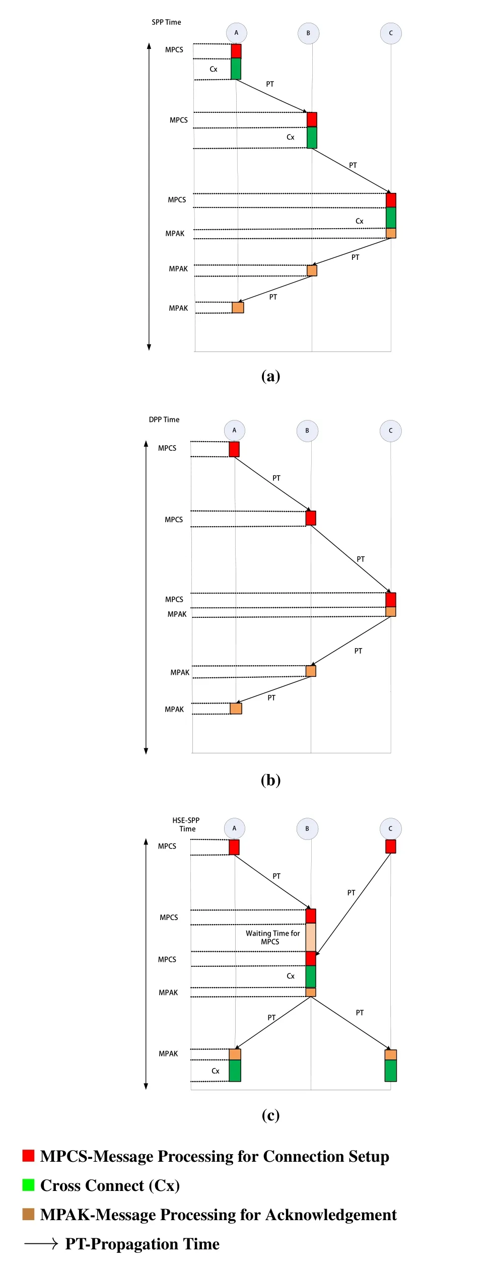
Figure 1. (a) Shared path protection (b) Dedicated path protection (DPP) (c) Halfway signaling exchange shared path protection(HSE-SPP).
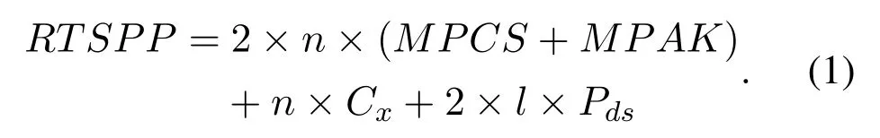
In equation (1),the connection recovery time (RT)of SPP strategy for n number of nodes and?length of the backup route is given.The parameter’s value is given in Table 1.
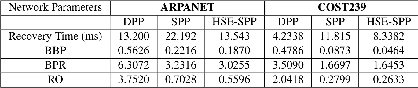
Table 1. Average values of different network parameters for various survivable strategies.
3.4.2 Dedicated path protection(DPP)connection recovery process
In DPP strategy,sharing of backup resources is not allowed therefore switches in the nodes of the backup route are already cross-connected.As a result,for connection recovery,time consumption in the crossconnection of switches does not consider.Figure 1(b)shows the connection recovery process in DPP strategy.It is shown in the figure that cross-connection time for sending a connection setup message does not consider.Equation(2)is the connection recovery process for n nodes and?length backup route.

3.4.3 Halfway signaling exchange shared path protection(HSE-SPP)connection recovery process
In Figure 1(c) HSE-SPP is shown.In this process,firstly; a halfway node on the backup is chosen as an intermediate node where the Signalling exchange will be done.For the backup route A-B-C,Node B is assigned as the backup route as shown in Figure 1(c).In HSE-SPP both the source and destination nodes generate connection establishment messages simultaneously after the occurrence of failure.In HSESPP,network resources are shared by backup routes,therefore,cross-connect time at the nodes is considered.After the reception of connection establishment messages from both the end nodes,Node B generates acknowledgment of the source and destination nodes.After the reception of acknowledgment,the connection establishment process is completed.
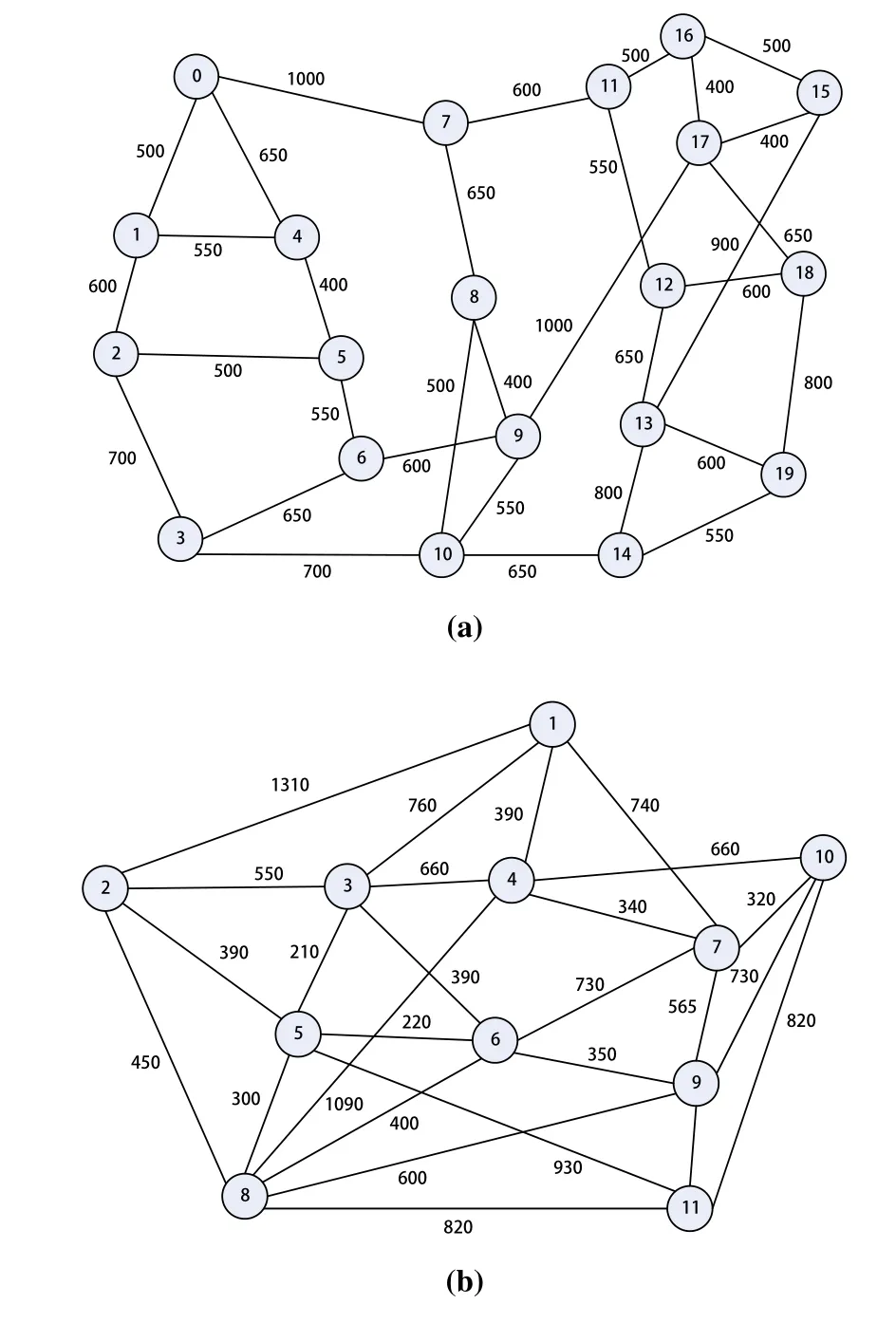
Figure 2. (a) ARPANET (20 nodes and 32 links) (b)Cost239(11 nodes and 26 links).

Figure 3.(a)Recovery Time in microseconds vs.Number of requests for ARPANET (b) Recovery time in microseconds vs.Number of requests for COST239.
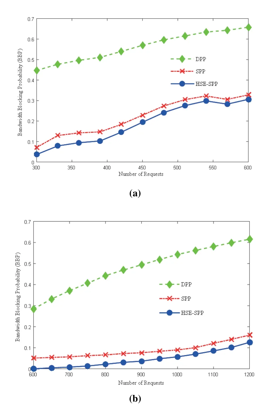
Figure 4. (a) Bandwidth blocking probability (BBP) vs.Number of requests for ARPANET (b)BBP vs.Number of requests for COST 239.
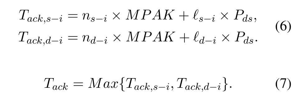
Let us considerns-i/nd-inodes on the backup routes between source/destination and intermediate nodes,?s-i/?d-iis the length of the backup route from source /destination node to the intermediate node.Recovery time of connection can be classified into two phases:connection setup message time(TCS)and acknowledge time(TACK).

TCSandTACKare given in equations(4)and(5)below.Connection setup message time is the time when both the connection setup messages reached the intermediate node.In other words,the setup time of the later arrived message is considered a connection setup time.LetTsetup,s-iandTsetup,d-iare the connection setup times of source node to the intermediate node and destination node to the intermediate node,respectively.
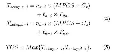
LetTack,s-i,andTack,d-iare the acknowledgment times from the intermediate node to the source node and intermediate node to the destination node,respectively.
3.4.4 Computation complexity for proposed recovery scheme
In algorithm 1,our proposed recovery scheme works in two steps:(1) in the first step,for primary route assignment (from lines 1 to 10),and (2) in the second step,for the recovery of failure (from lines 11 to 20).We consider that the number of connection request for the network isNr.The connection request for the primary route is searched by using Dijkstra’s algorithm (line 4 in the algorithm) with complexityO(N ×logN),whereNbe the number of nodes.If the primary route is available,then the FSs are allotted to the links of the primary route as mentioned in lines 6 to 8 in the algorithm.The computational complexity of the step first is given asO(Nr ×N ×logN).For the second step,the recovery of the failure,where we consider the failure of the network links.In the algorithm,line 13 shows the link failure.Searching for the backup route and bandwidth recovery is provided inline 15 to 21.Similarly,for the primary route,search for a backup route takesO(N × logN) time units.Hence,the complexity of the second step can be computed asO(L × F × N × logN),whereLbe the links andFbe the number of a failed request in the network.Therefore,the complexity of our proposed halfway signal exchange-shared path protection(HSE-SPP)isO(N ×logN(Nr+L×F)).
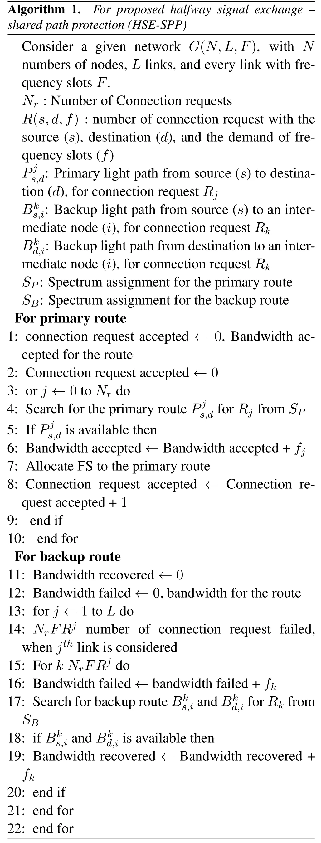
Algorithm 1.For proposed halfway signal exchange -shared path protection(HSE-SPP)Consider a given network G(N,L,F),with N numbers of nodes,L links,and every link with frequency slots F.Nr :Number of Connection requests R(s,d,f) :number of connection request with the source (s),destination (d),and the demand of frequency slots(f)Pj s,d:Primary light path from source(s)to destination(d),for connection request Rj Bks,i:Backup light path from source(s)to an intermediate node(i),for connection request Rk Bkd,i:Backup light path from destination to an intermediate node(i),for connection request Rk SP:Spectrum assignment for the primary route SB:Spectrum assignment for the backup route For primary route 1:connection request accepted ←0,Bandwidth accepted for the route 2:Connection request accepted ←0 3:or j ←0 to Nr do 4:Search for the primary route Pj s,d for Rj from SP 5:If Pj s,d is available then 6:Bandwidth accepted ←Bandwidth accepted+fj 7:Allocate FS to the primary route 8:Connection request accepted ←Connection request accepted+1 9:end if 10:end for For backup route 11:Bandwidth recovered ←0 12:Bandwidth failed ←0,bandwidth for the route 13:for j ←1 to L do 14: NrFRj number of connection request failed,when jth link is considered 15:For k NrFRj do 16:Bandwidth failed ←bandwidth failed+fk 17:Search for backup route Bks,i and Bkd,i for Rk from SB 18:if Bks,i and Bkd,i is available then 19:Bandwidth recovered ←Bandwidth recovered +fk 20:end if 21:end for 22:end for
IV.SYSTEM MODEL
In this section,the definition and notations are presented.Let us considerNnodes,Llink,andFfrequency slots per link in the network.Ris a set of connection requests for connection establishment.PandBare the sets of the primary and backup routes of the connection requests.
4.1 Notations
na network node?n ∈N
?network link?? ∈L
fa frequency slot?f ∈F
ra connection request?r ∈Rpa primary route?p ∈P ba backup route?b ∈B BBackup route
?f fthfrequency slot on link?
?p fthfrequency slot of link?assignedpthprimary route
?b fthfrequency slot of link?assigned tobthbackup route
RTrRecovery time of requestr,?trε Tr
RTC Recovery time constraint
The values of different network parameters are as follows:
·Detection of failure,the time taken by the node to detect the failure,we consider the detection time of the failure,Dfis 10μs[48].
·Message processing (MPCS) connection setup time at the node is 10μs.
·The propagation time in the signal(Pds)on each link is 400μs for every 80km.
·Optical cross-connection is the connection establishment time (Cx),we consider the crossconnection time is 10ms.The optical crossconnection time takes on values 10ns,10μs,500μs,and 10ms as provided in reference[45].The optical cross-connection time is taken low(10ns) the protection switching time is in the increasing order as follows:a)shared link,b)dedicated path,and c)shared path.If the optical crossconnection time is high (10ms),then the protection switching time is in the increasing order as follows:a)dedicated path,b)shared link,and c)shared path.
·The number of links(bl)in the backup light path.
·n,be the Number of nodes andMPAKbe the message acknowledgment time from destination to source andlbe the length of the backup light path.
4.2 Network Constraints
In this section,different networking constraints are presented which are considered at the time of survivable network design.
4.2.1 Maximum capacity of the link
The number of frequency slots on the link always less than or equal to the maximum FSs available on the link.

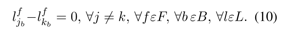
4.2.2 Spectrum continuity constraint for the primary and backup route
In continuity,the same frequency slot of each link must be assigned to the route.
1.For primary route:
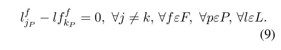
2.For a backup route:
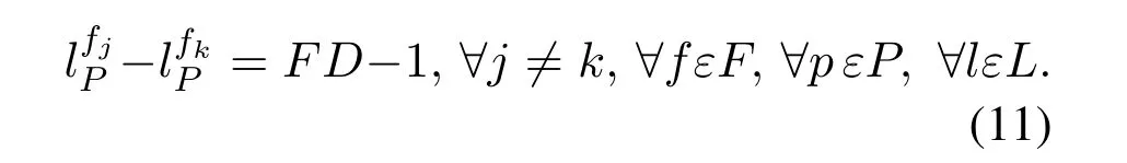
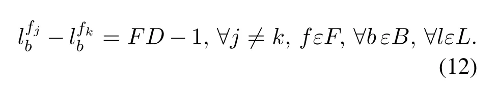
4.2.3 Spectrum contiguity constraint for the primary and backup route
In contiguity,contiguous frequency slots must be assigned therefore the difference in indexing of first and last frequency slots of link always less than one of the number of frequency slots demand.Let us consider FD is the number of frequency slot demand arrives.
1.For primary route:
2.For a backup route:
4.2.4 Recovery time constraint
Recovery time constraint is the maximum time for connection re-establishment after the failure.
V.RESULTS AND DISCUSSION
The experimental simulation has been done on MATLAB 2015 version with Microsoft window 10 operating,Intel core i5 1.80GHz,with 8GB Read Access Memory.The connection requests are generated randomly by considering two topologies viz.ARPANET(20 nodes,and 32 links),and COST239 topology(11 nodes,and 26 links)shown in Figure 2(a)and(b).
The connection requests are generated randomly with heterogeneous frequency slots between 1 to 8.All three strategies are proactive survivable strategies where backup routes are decided at the time of connection setup.Furthermore,the path-based backup route is assigned to the connection requests[10,16].In path-based,the backup route contains neither intermediate node nor links of the primary route.Both primary and backup routes must pursue spectrum continuity and contiguity constraints[38].Moreover,the connection is accepted only when the backup route satisfies connection recovery constraints.For route K(=3)shortest path routing is used.The performance of all three strategies is evaluated under four network parameters given below.
5.1 Connection Recovery Time
Connection recovery time is the time between the instants of the connection recovery process initiated and the acknowledgment received by the source and destination simultaneously.After the occurrence of failure,the re-establishment of communication must be as soon as possible.Therefore,connection recovery time must be low for rapid connection establishment.To achieve fast connection recovery,a recovery time constraint has been introduced.In Figure 3(a)and(b)the recovery time constraints(RTC)are 45 and 21 ms for ARPANET and COST239 topologies,respectively.Hence,the RT must be less than 45 (for ARPANET)and 21ms(for COST239).
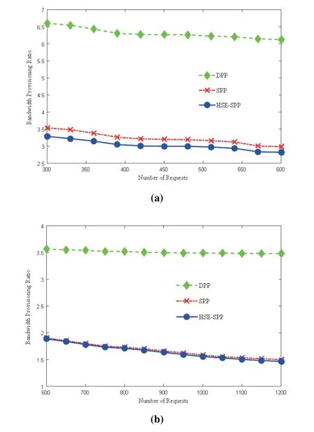
Figure 5. (a)Bandwidth provisioning ratio(BPR)vs.Number of requests for ARPANET.(b) BPR vs.Number of requests for COST239.
The values of different network parameters for different recovery schemes considered for simulation are given in Table 1.Figure 3(a) and (b) show the connection recovery time when the number of connection requests increases,the recovery time gets reducing.In ARPANET topology,the recovery time of HSE-SPP is almost equal to DPP,but as the number of connection requests increases,the RT also increases,however,it is much lower than the SPP.And in the case of COST239,the recovery time of HSE-SPP is between DPP and SPP strategies.Since in ARPANET network backup routes are longer,therefore,the performance of HSE-SPP is comparable to DPP.Hence,HSE-SPP performs better when backup routes are longer.In Table 1 for the comparison average recovery time is mentioned.
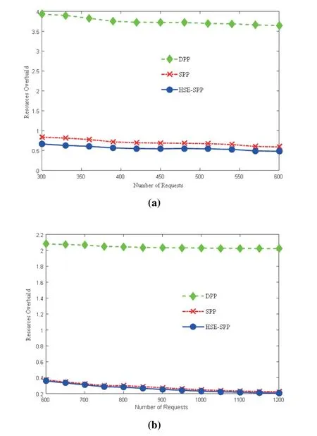
Figure 6. (a) Resource overbuild ratio vs.Number of requests for ARPANET(b)Resource overbuild ratio vs.Number of requests for COST239.
5.2 Bandwidth Blocking Probability(BBP)
BBP is one of the network parameters for evaluating the performance of the proposed and existing strategies.It is defined as the ratio of the total number of bandwidths rejected to the total number of bandwidth demanded[17,38].Connection request rejects either of the primary and backup routes unavailable.BBP must low under the given network constraints.Figure 4(a) and (b) show the bandwidth blocking probability (BBP) of survivable strategies with the number of connection requests for ARPANET and COST239 topologies,respectively.
When the number of connection requests less,network resources are large enough for the establishment of connection requests,which results in low BBP.As the connection request increases,BBP also increases due to the network resources crunch.Among all the three strategies,Our proposed halfway signaling exchange shared path protection(HSE-SPP)strategy has lower bandwidth blocking probability compared to shared path protection (SPP) and dedicated path protection(DPP).Although proposed HSE-SPP and SPP uses backup multiplexing for resource sharing,but in SPP connections are rejected due to connection recovery constraints.On the other hand,network resource utilization is inefficient in DPP due to higher redundancy backup resources results in the highest BBP.The average BBP for ARPANET topology in our proposed strategy HSE-SPP is 0.1870,and for SPP and DPP are 0.2216,and 0.5626 respectively.Furthermore,COST239 is 0.0464,0.0873,and 0.4786 for HSE-SPP,SPP,and DPP,respectively.
5.3 Bandwidth Provisioning Ratio(BPR)
In order to evaluate the average number of frequency slot assignments for the establishment of a frequency slot demand,we computed the bandwidth provisioning ratio(BPR).BPR is defined as the ratio of the total FS used to the total FSs demand accepted.In HSESPP and SPP the backup resource sharing is increasing with the connection requests,thereby BPR decreases as mentioned in Figure 5(a)and(b).
For DPP at a high number of connection requests,the shortest routes are only accepted because the possibility of resources available on longer routes becomes very less.As a result,BPR decreases.The average bandwidth provisioning ratio for ARPANET topology in our proposed HSE-SPP is 3.0255 and for SSP and DPP are 3.2316 and 6.3072 respectively and the average of BPR for COST239 is 1.6453 for HSE-SPP and for SPP and DPP are 1.6697 and 3.5090 respectively.
5.4 Backup Resource Overbuild Ratio
Backup resource overbuilds measure how much redundancy backup FSs are needed over per frequency slot acceptance.It is defined as the ratio of the total FS used by the backup route to the total number of FS accepted.In HSE-SPP and SPP overbuild ratio is low due to backup resources sharing,while in DPP resources overbuild is high.Figure 6(a) and (b)show that our proposed strategy has a low overbuild ratio as compared to SPP and DPP for ARPANET and COST239 topologies.
The average backup resource overbuild ratio(BROR) for ARPANET topology for HSE-SPP,SPP and DPP are 0.5596,0.7028,and 3.7520,and for COST 239 are 0.2633,0.2799,and 2.0418 respectively.
VI.CONCLUSION
In this paper,a halfway signaling exchange mechanism for rapid connection recovery is proposed.In the proposed HSE-SPP strategy,a parallel connection setup messages by both the end nodes are initiated.HSE-SPP has been evaluated on network parameters connection recovery time,BBP,BPR,and resource overbuild ratio.Simulation results show that the proposed strategy has better performance than the existing SPP and DPP approaches.In the future HSE can also be applied in designing other survivable problems such as wireless communication,multicore optical network,latency in sensor networks,and for duallink failure.
- China Communications的其它文章
- Correlation-Aware Replica Prefetching Strategy to Decrease Access Latency in Edge Cloud
- Secure Transmission in Downlink Non-Orthogonal Multiple Access Based on Polar Codes
- M2LC-Net:A Multi-Modal Multi-Disease Long-Tailed Classification Network for Real Clinical Scenes
- DEEPNOISE:Learning Sensor and Process Noise to Detect Data Integrity Attacks in CPS
- Beamforming Optimization for RIS-Aided SWIPT in Cell-Free MIMO Networks
- Security Risk Prevention and Control Deployment for 5G Private Industrial Networks