Dynamic Response Analysis of a Floating Mooring System
LE Conghuan, DING Hongyan, and ZHANG Puyang
1) State Key Laboratory of Hydraulic Engineering Simulation and Safety, Tianjin 300072, P. R. China
2) School of Civil Engineering, Tianjin University, Tianjin 300072, P. R. China
3) Key Laboratory of Coast Civil Structure Safety, Ministry of Education, Tianjin University, Tianjin 300072, P. R. China
Dynamic Response Analysis of a Floating Mooring System
LE Conghuan1),2),*, DING Hongyan1),2),3), and ZHANG Puyang1),2),3)
1) State Key Laboratory of Hydraulic Engineering Simulation and Safety, Tianjin 300072, P. R. China
2) School of Civil Engineering, Tianjin University, Tianjin 300072, P. R. China
3) Key Laboratory of Coast Civil Structure Safety, Ministry of Education, Tianjin University, Tianjin 300072, P. R. China
An innovative floating mooring system with two or more independent floating mooring platforms in the middle and one rigid platform on each side is proposed for improving efficiency and safety in shallow water. For this new system, most of collision energy is absorbed through the displacement of floating platforms. In order to illustrate the validity of the system, a series of model tests were conducted at a scale of 1:40. The coupled motion characteristics of the floating mooring platforms were discussed under regular and irregular waves, and the influences of wave direction and other characteristics on dynamic response of the system were analyzed. The results show that the mooring system is safest at 0° of wave incident angle, whereas the most dangerous mooring state occurs at 90° of wave incident angle. Motion responses increase with the increase of wave height, but are not linearly related to changes in wave height.
floating mooring system; model test; wave characteristics; impact force; motion response
1 Introduction
In offshore oil and gas production, the shuttle tanker will be needed to transport crude oil to port regularly due to limited storage capacity of oil platform. For some small and medium oil platforms or the floating production systems which require a higher stability, vessels cannot be berthed beside them too closely for safety reason. So a mooring system is needed to assist vessel operations. Proposed in this paper is an innovative combination of rigid and flexible mooring platforms (Fig.1), which consists of two or more independent floating mooring platforms in the middle section and one rigid mooring platform on each side. The floating mooring platform consists of a hull, four foundations, and four anchor chains. The hull consists of four pontoons and two dolphins with fenders and the anchor chains connect the hull to foundations (Fig.2). The rigid mooring platforms are to enhance the mooring system constraints and improve positioning effects. Substantial buoyancy provided by submerged pontoons exceeds the weight of floating mooring platform. Thus, the extra buoyancy always keeps anchor chains in tension. With respect to the horizontal degrees of freedom, the floating mooring platform is compliant, whereas with respect to the vertical degrees of freedom, it is not allowed to move freely. Due to the structure flexibility, a floating mooring platform encounters lesser impact from waves and vessels, and hence has good performance in rough seas. In addition, the time needed to construct a platform can be reduced and the reuse of a platform simplified by the usage of the bucket foundation (Ding and Zhang, 2008; Guo and Wang, 2009; Leet al., 2011, 2013). In general, the floating mooring platform resembles the simple tension leg platform (TLP), designed for relatively shallow water, and has favorable motion characteristics as the TLP, but does not demand high initial investment and operation costs while reducing complexity of construction and long project duration.
For the last two decades, many studies have been focusing on various aspects of TLPs. Vickery (1995) studied the dynamic response of square TLPs under normal environmental loads. Ahmad (1996) investigated the coupled response of a TLP to random waves characterized by a spectrum for long-crested seas. Considering the coupling of all the degrees-of-freedom, Chandrasekaran and Jain (2002a, b) studied the dynamic behavior of triangular TLPs under regular and irregular wave conditions in both time and frequency domains. Chandrasekaranet al.(2007a, b) further analyzed the dynamic response of triangular TLPs to different waves with incident angles varying from 0° through 90°. Their studies indicated that wave incident angles influence the coupled dynamic response of triangular TLPs in all degrees of freedom except for heave. Besides frequently occurring environmental forces due to waves, currents,etc., TLPs have to withstand those less probable forces due to collisions with ships, icesheets or giant sea creatures. Siddiqui and Ahmad (2003)discussed the response behavior of TLPs under less probable impulsive forces. Khanet al.(2004, 2006) assessed the reliability of conventional TLP tethers under short duration impulsive loading by performing a nonlinear dynamic analysis in the time domain.
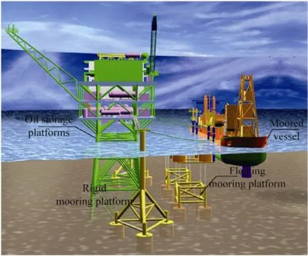
Fig.1 The newly designed floating mooring system.
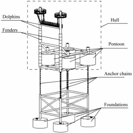
Fig.2 The floating mooring platform.
In most of the available literatures conventional TLPs were studied as deep-water oil exploration platforms. In contrast to conventional TLPs, the floating mooring platform is used as a shallow-water mooring platform. Dynamic behavior of the floating mooring platform is more complicated due to the combined environmental and vessel loads. Because the floating mooring platform has a relatively small size and is moored in relatively shallow waters, waves may be of greater influence on it than on other conventional floating offshore systems (Johanninget al., 2007).
The environmental loads can cause periodic impact on a floating mooring platform and a moored vessel. As shown in Fig.3, the hull subjected to buoyancy, tensile force of anchor chain, wave loads, mooring force and ship impact force, will excurse from its equilibrium position and cause the surrounding water motion. Most impact energy is absorbed in the form of displacement of the hull, and lesser energy is absorbed in the form of deformation of the floating platform and the vessel. Large hull excursion will threaten the oil storage platform safety because of the short distance between the floating mooring platform and the oil storage platform. In the long run, harsh marine environment may cause repeated collisions between the platform and vessel and result in severe vibration or deformation of them. So it is essential to analyze the dynamic response of the floating mooring system to environmental loads. In this study a series of tests was conducted on a 1:40 scale model under different conditions to qualitatively and quantitatively analyze motion characteristics and dynamic response of a newly designed floating mooring system.
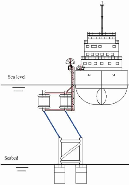
Fig.3 Schematic diagram of energy absorption.
2 Mechanical Analysis of Floating Mooring Platform
Collisions between a floating mooring platform and a moored vessel occur under wave actions. To determine the impact forces acting on the platform and vessel, the analysis is simplified by considering the hull as a rigid body and the floating mooring platform as an inverted pendulum structure (Fig.4). The equation of motion of the hull is obtained as:

where {s} is the displacement vector of the hull; [M], [C], and [K] represent the mass, damping and stiffness matrices of the hull, respectively and are obtained based on Ahmad (1996). [K] is given as:
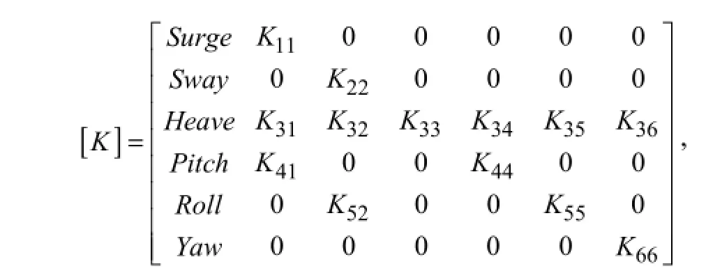
and stiffness in the surge degree of freedom

T0is the initial pre-tension in anchor chain; ΔT1is the change in tension of anchor chain;lis the initial length of anchor chain;s1is the arbitrary displacement in the surge degree of freedom; {F(t)} is the external force vector which is the sum of wave loadsFwand moored vessel acting loads Fs and is given as:

the external force in the surge, sway and heave degrees of freedom being designated asF11,F21andF31, respectively. The moment of external forces about thex,yandzaxes are designated asF41,F51andF61, respectively. Wave force vectorFwis calculated by appropriate wave theories based on the hull size and wave parameters (Li, 1999). By only considering the collision it is difficult to obtain the analytical solution to the actual acting forceFsbetween the platform and the vessel, whereas the numerical solution can be obtained by the hydrodynamic software MOSES.
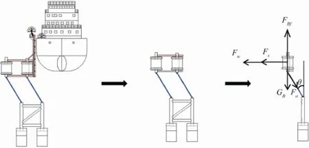
Fig.4 Schematic diagram of mechanical analysis.
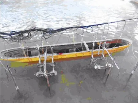
Fig.5 Model of floating mooring system (scale 1:40).
3 Experiment Design
3.1 Test Models
3.1.1 Mooring platform
Model tests were conducted on a 1:40 scale model (Fig.5) designed by gravity and inertial force similarity. Geometry parameters of mooring platform are shown in Table 1. In the following analysis a ‘prototype size (model size)’ is used.
3.1.2 Fender
Fenders are installed on the dolphins of the mooringplatform. The fender configuration is geometrically similar to that of the prototype, and mechanical properties curveof fenders model is similar to that of the prototype by adjusting fender thickness.
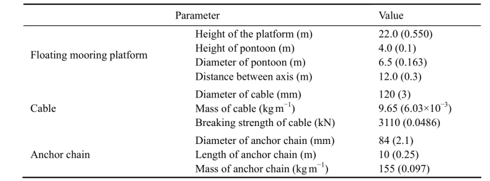
Table 1 Main characteristic parameters of the floating mooring platform
3.1.3 Cable and anchor chain
Characteristics parameters of the cable model and anchor chain model are shown in Table 1. The cable is simulated by a combination of nylon cord and spring, in which the tension-elongation curve is calculated by changing the length of spring to satisfy the following equation (JTJ/T 234-2001).

whereTmis the cable tension (N) in the model;Cpis the elasticity coefficient of the prototype cable, which is equal to1.540×104 MPa and 2.697×10⁶ MPa for nylon cable and steel cable, respectively;dpis the diameter (m) of the prototype cable; ΔS/Sis the relative elongation of the prototype cable andSis the initial length;nis the index, withn=1.5 for steel cable andn=3 for nylon cable;λis the model scale.
3.1.4 Vessel
Vessel parameters are shown in Table 2. The vessel model was made of wood and maintained geometric similarity to prototype. Lead weights were used to ballast vessel to simulate different load conditions. The draft, weight, center of gravity, mass moment of inertia and natural period of ship model are similar to those of the prototype.
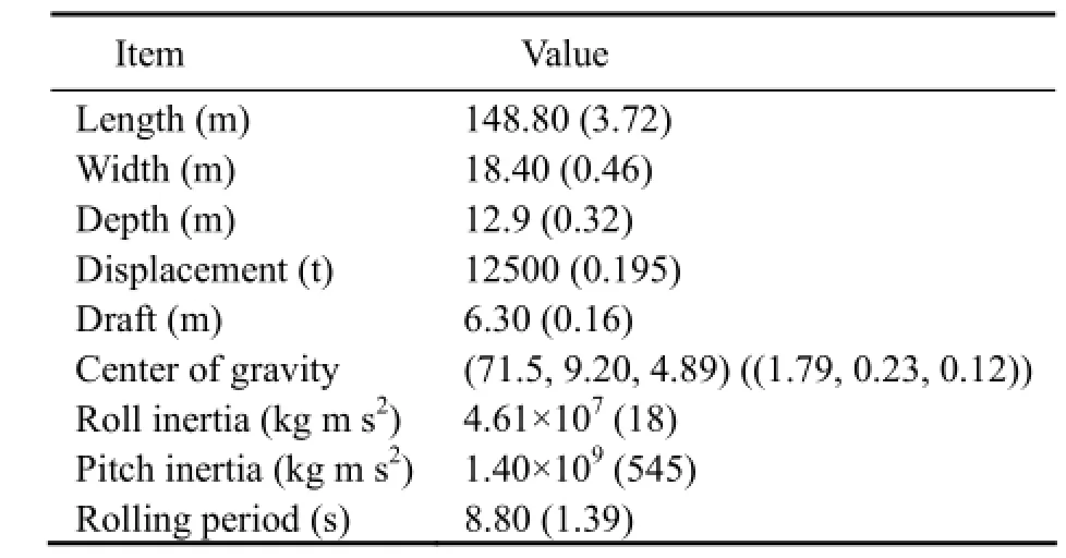
Table 2 Main characteristics of vessel
3.2 Experiment Apparatus
The model basin is 40 m long, 11 m wide, and 1 m deep (Fig.6). It is equipped at one end with a wave maker capable of generating both regular and random waves, and with a wave-absorbing beach at the other end (JTJ/T 234-2001). Measuring devices include capacitance wave height gauges, accelerometer transducers, displacement transducers, force transducers, camera system, wave calibration system, water thermometer, signal amplifier, dynamic wave data acquisition and processing system, and data acquisition and processing system for hydraulic model.
The general layout of the entire testing assembly is shown in Fig.7. Three-degree-of-freedom acceleration sensors are laid out at the top of dolphins of bow mooring platform A and stern mooring platform B for measuring the accelerations in the three directions of surge, sway and heave, and displacement transducers are arranged on both floating mooring platforms. The displacement direction is positive when the platform moves away from the moored ship, being otherwise negative. Force sensors are installed the each junction of anchor chains and the foundation to measure the anchor tension, and at the ends of 8 mooring cables force sensors are arranged to measure the tension of mooring cables. The parameters of the transducers are given in Table 3.
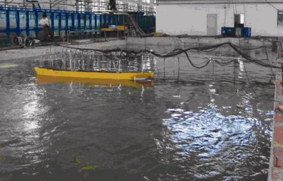
Fig.6 Model basin.
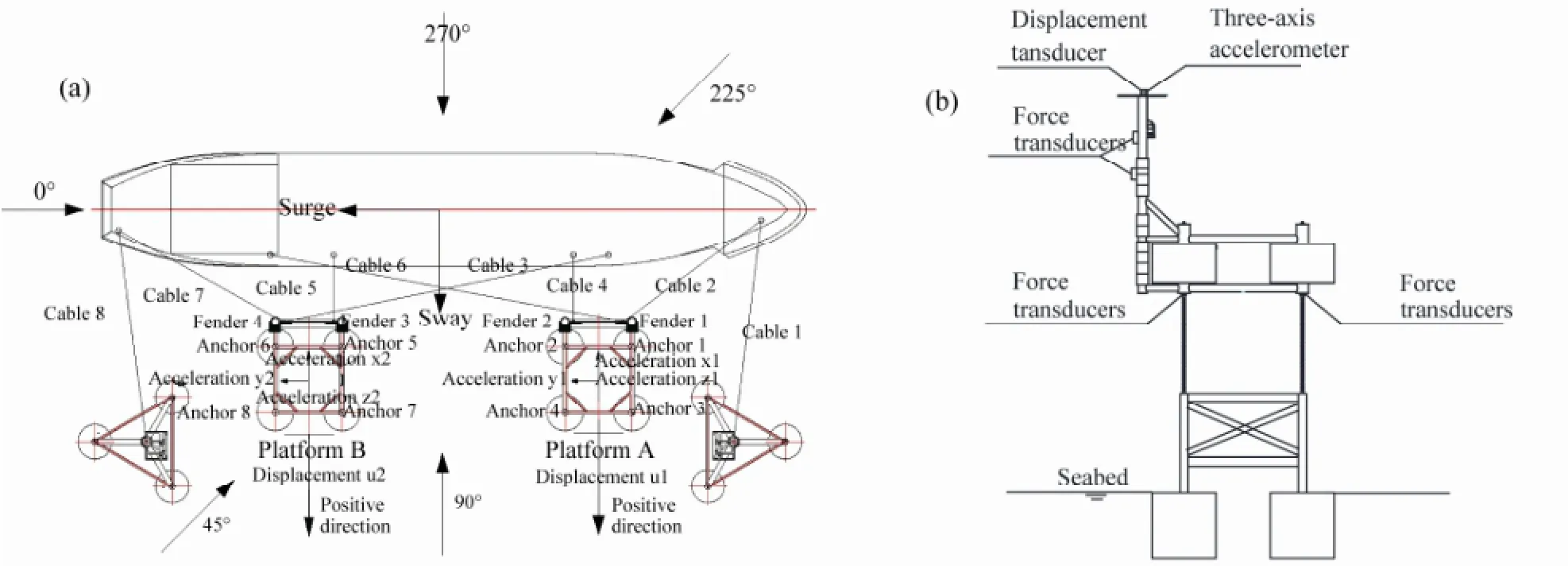
Fig.7 Layout of the entire testing assembly. (a) Arrangement of instruments and wave incident angles. (b) Side view of the transducers arrangement on the floating mooring platform.

Table 3 List of transducers
3.3 Test Conditions
A series of mooring tests were conducted under the conditions of the extra buoyancy of platform of 300 t/4.69 kg, ship displacement of 12500 t/195 kg and water depth of 25 m/0.625 m with regular and irregular waves to analyze the influence of wave characteristics (wave incident angles are shown in Fig.7). The simulations were performed under the postulated operational conditions (1-year return period, wave height of 2 m, wave period of 6 s) and extreme conditions (50-year return period, wave height of 4.5 m, wave period of 8.2 s) in the eastern Bohai Sea of China (Table 4). And JONSWAP wave spectrum (Hassleman,et al., 1973) was adopted for irregular wave simulation.

Table 4 List of tests for floating mooring
4 Experiment Results and Analysis
A large quantity of experimental data was obtained by the data acquisition system. Fourier filtering was applied to these data, which were transformed into the prototype data based on the similarity theory.
4.1 Influence of Wave Direction
Fig.8 depicts the displacement-time curves of floating mooring platforms under regular waves with a wave height of 2 m, a period of 6 sec, and varying wave incident angles from 0° to 270° (Tests 3, 5 to 8 in Table 3). The motion of two floating mooring platforms shows periodic oscillation. When the wave incident angle is 0°, the movement of platforms A and B is gentle and shows both low-frequency and high-frequency characteristics, and the motion ranges of the two floating mooring platforms are similar. When the wave incident angle is 90°, the floating mooring platforms mainly show the high-frequency sway motion, and the movement amplitude of the floating mooring platforms reaches the peak value. When the wave incident angles are 225° and 270°, the displacement-time curves show clear high frequency and low frequency characteristics. The low frequency motion is due to the swing of the ‘inverted pendulum’ system consisting of the anchor chain, floating mooring platform and vessel, while the high frequency motion is caused by platform vibrations under the action of waves and vessel impact. The results show that the low-frequency responses of the floating mooring platform are different for different wave incident angles. Only when the wave incident angle is 90°, the low frequency motion of the floating mooring platform is inhibited by vessel motion.
Fig.9 shows the maximum displacements of the two floating mooring platforms in the sway directions for wave incident angles varying from 0° to 360°. When the wave incident angle is 0°, the movements of platforms A (bow mooring platform) and B (stern mooring platform) are gentle, and the displacements of the platforms are small. When the wave incident angle is between 0° and 180°, the platforms mainly drift in the negative sway direction (close to the vessel), and the maximum displacement of platform A is larger than that of platform B in this direction due to the oblique vessel impact caused by the uneven distribution of vessel mass. When the wave incident angle is between 180° and 360°, the sway of the platforms mainly takes place in the positive direction. Fig.10 shows the maximum excursion from their initial equilibrium positions of the two floating mooring platforms for different wave incident angles, and the comparisons between the calculations and experiments. The overall agreement is good except for the platform B deviation of 102% at 90° wave incident angle, and the deviations within 45% at other wave incident angles. The calculated excursions of the two platforms are similar, which indicates that the two platforms absorb approximately same amount of energy. In contrast, the experimental results show considerable difference in platform excursions, indicating that the energy is unevenly absorbed by the two platforms. The maximum platform excursion around 3.43 m occurred at the wave incident angle of 270°, while the minimum platform excursion around 0.59 m occurred at the 0° wave incident angle.
Fig.11 shows the mean impact forces on floating mooring platforms for different wave directions. The 0° wave incident angle causes gentle platform motions and smallimpact force while the beam seas (90°, 270°) produce violent platform motions and great impact force. Considerable deviations can be found by comparing the calculated and experimental results. It can also be seen that the measured mean impact forces on the two platforms are quite different, whereas the calculated mean impact forces are similar under the same wave incident angle. Similar to the displacement response, it is also caused by uneven distribution of vessel mass resulting in oblique impacts under wave actions. And, because the impact is a stochastic process, experimental errors would have a significant effect on it.
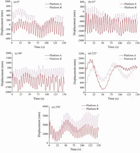
Fig.8 Displacement-time curves of platforms for different wave directions.
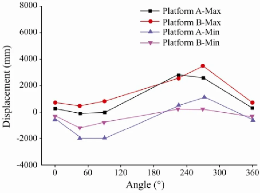
Fig.9 Maximum displacement of platforms for different wave directions
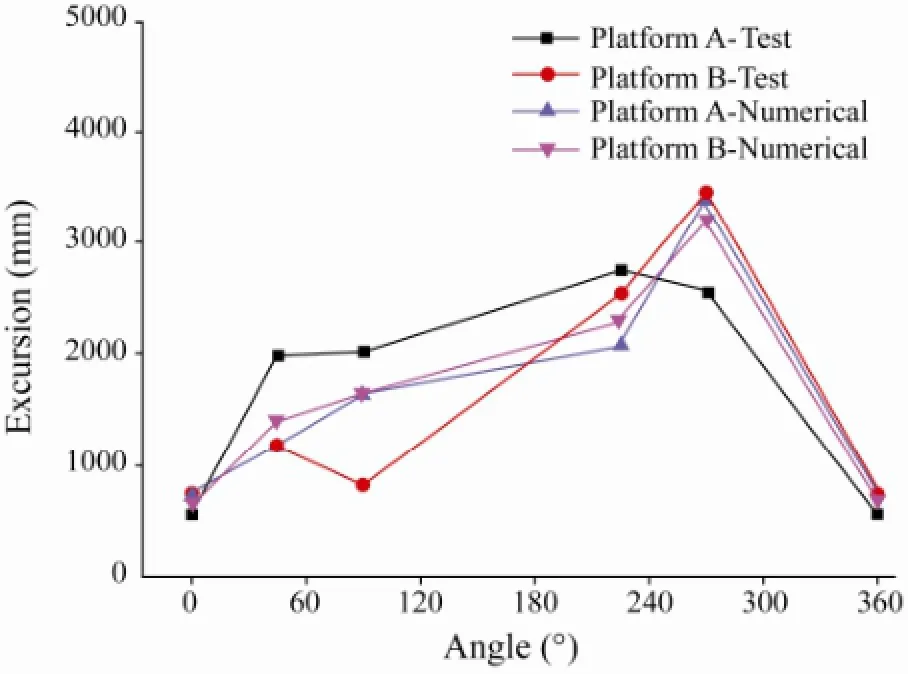
Fig.10 Comparison of maximum platform excursions based on measurements and numerical calculations
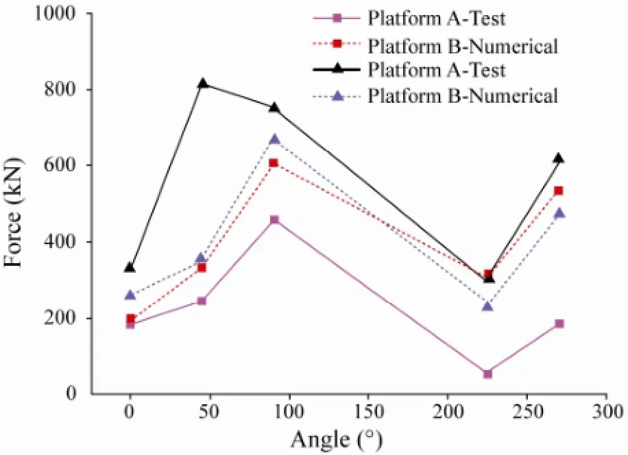
Fig.11 Mean impact forces on platforms for different wave directions
Table 4 shows the mooring forces of cables for different wave directions. All the maximum mooring forces of cables are less than the cable breaking strength of 3110 kN, meeting the strength requirements. Nevertheless the maximum mooring forces do not occur simultaneously in different cables under different wave incident angles. When the wave incident angle is larger than 180°, floating mooring platforms can be squeezed by the vessel, the mooring forces in all cables are relatively small, and the force distribution shows a serrated pattern with small mooring forces in bow and stern cables (cable 1 and cable 8) and short breast cables (cable 4 and cable 5), and with large mooring forces in other cables. When the wave angle is smaller than 180°, the vessel drags the floating mooring platform by cables due to wave actions, and the mooring force in all cables are relatively large, especially for the short breast cables sharing larger proportion of mooring forces. And the maximum mooring force appears in the short breast cable (cable 4) when the wave incident angle is 45°. Due to a certain phase difference between the floating platform motion and moored ship motion, the angle 45° is an unfavorable wave incident angle for the cable force.
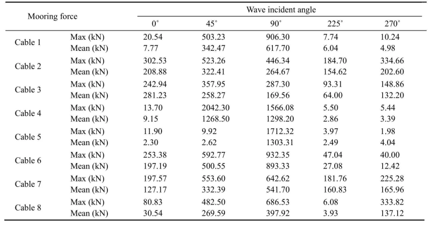
Table 4 Cable mooring force for different wave incident angles
Fig.12 shows the time history of the tension of anchor chains at the 270° wave incident angle. Chains 1 and 4, and chains 5 and 8 are at platforms A and B, respectively (Fig.7a), and are chosen to illustrate the tension variations of anchor chains. Initial pre-tension in all anchor chains are equal. Large periodic variations of the tension can be seen under wave impact, and different anchor chains have different variation patterns, even on the same platform. Although the tension variations of anchor chains have large difference, the tension in all anchor chains is always larger than zero.
Fig.13 shows the maximum tension of anchor chains in laboratory experiments and numerical calculations for different wave incident angles. The plots reveal very good overall agreement except for the maximum deviation of 42.3% for anchor chain 5 at the 90° wave incident angle. The variations of the maximum tension show similar trends at different wave incident angles, and the maximum tension of anchor chains occurs at the 90° wave incident angle.
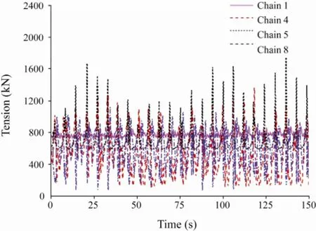
Fig.12 Tension-time curves of anchor chains at 270° wave incident angle

Fig.13 Maximum tension in anchor chains for different wave incident angles.
4.2 Influence of Wave Characteristics
Table 5 shows the maximum impact forces at fenders under different wave heights and periods and 90° wave incident angle. The impact forces on different fenders have great differences under different wave actions, even under the same wave conditions. The results indicate that the impact forces are positively correlated with wave heights, larger wave heights leading to larger resultant impact forces.
Fig.14 shows the displacement responses of floating mooring platforms under the same wave conditions as in Table 5. The motions of floating mooring platforms under regular waves show clear periodicity, whereas the motions under random waves are irregular. The amplitudes of platform movements increase with the increase of wave heights. The movements of platforms A and B are small and uniform, around 500 mm under regular waves with a wave height of 1 m and wave period of 5 s. By contrast, the movements of the platforms are about 1500 mm and 2990 mm under regular waves with a wave height of 2 m and period of 6 s, and a wave height of 4.5 m and period of 8.2 s, there being an increase of 200% and 498% comparing with the small wave conditions, respectively. Under random waves with a significant wave height of 2 m and peak wave periods of 5 s and 6 s, the maximum movements of the two platforms are roughly the same,i.e., about 3500 mm, whereas with a wave height of 4.5 m and period of 8.2 s, the movement increases to 4200 mm. The maximum excursions of the floating platforms are compared under different wave conditions in Table 6. The maximum excursion from platforms’ equilibrium positions reaches 4460 mm under the extreme wave conditions. Thus, the platform movement increases with the increase of wave height; however, the movement responses are not linearly related to changes in wave height.

Fig.14 Measured displacement-time curves of platforms under different waves.

Table 5 Maximum impact forces on fenders under different waves

Table 6 Maximum excursions of floating platforms under different waves
5 Conclusions
Using model tests and numerical analysis, dynamic responses of a floating mooring system are investigated under different wave conditions with the following conclusions:
1) The experimental and numerical findings show that the newly designed floating mooring system is suitable for the shallow-water operation. The floating platform movements, the impact forces between platforms and vessels, and the tension of anchor chains are critical indicators for assessing the stability and assisting the design of floating mooring platforms.
2) The wave incident angle is a critical factor in influencing dynamic responses of floating mooring systems. The 0° wave incident angle corresponds to the smallest dynamic response and the safest mooring state, while the 90° wave incident angle corresponds to the maximum dynamic response with the maximum impact force and tension of anchor chains, and thus the most dangerous mooring state of a floating mooring platform.
3) The patterns of platform movement show apparent regularity under regular waves and irregularity under random waves. Movement amplitudes of floating mooring platforms are positively correlated with wave heights. Nevertheless, the motion responses are not linearly related to changes in wave heights.
4) The calculated motion responses of the floating mooring system have been validated against the lab experiments. The overall agreement between the measurements and the numerical calculations is satisfactory.
Acknowledgements
The authors would like to acknowledge the support of the National Natural Science Foundation of China (Grant No. 51309179), the National High Technology Research and Development Program of China (863 Program, Grant No. 2012AA051705), the International S&T Cooperation Program of China (Grant No. 2012DFA70490), the State Key Laboratory of Hydraulic Engineering Simulation and Safety (Tianjin University), and the Tianjin Municipal Natural Science Foundation (Grant Nos. 14JCQNJC07000 and 13JCYBJC19100).
Ahmad, S., 1996. Stochastic TLP response under long crested random sea.Computers Structures, 61 (6): 975-993.
Chandrasekaran, S., and Jain, A. K., 2002a. Dynamic behaviour of square and triangular TLPs under regular wave loads. Ocean Engineering, 29 (3): 279-313.
Chandrasekaran, S., and Jain, A. K., 2002b. Triangular configuration tension leg platform behaviour under random sea wave loads. Ocean Engineering, 29 (15): 1895-1928.
Chandrasekaran, S., Jain, A. K., and Gupta, A., 2007a. Influence of wave approach angle on TLP’s response. Ocean Engineering, 34 (8-9): 1322-1327.
Chandrasekaran, S., Jain, A. K., Gupta, A., and Srivastava, A., 2007b. Response behaviour of triangular tension leg platforms under impact loading. Ocean Engineering, 34 (1): 45-53.
Ding, H. Y., and Zhang, P. Y., 2008. Prototype tests during pull up processes of a multi-bucket foundation dolphin platform. Rock and Soil Mechanics, 29 (6): 1585-1588 (in Chinese).
Guo, Z., and Wang, L. Z., 2009. Quasi-static analysis model of suction caisson mooring line. The Ocean Engineering, 27 (4): 1-9.
Hasselmann, K., Barnett, T. P., Bouws, E., Carlson, H., Cartwright, D. E., Enke, K., Ewing, J. A., Gienapp, H., Hasselmann, D. E., Kruseman, P., Meerburg, A., Muller, P., Olbers, D. J., Richter, K., Sell, W., and Walden, H., 1973. Measurement of wind-wave growth and swell decay during the Joint North Sea Wave Project (JOSWAP). Deutschen Hydorgraphischen Zeitschrift, Erganzunscheft, 13: No. A.
Johanning, L., Smith, G. H., and Wolfram, J., 2007. Measurements of static and dynamic mooring line damping and their importance for floating WEC devices. Ocean Engineering, 34 (14-15): 1918-1934.
JTJ/T 234-2001, Ministry of Communications of the People’s Republic of China, 2002. Wave Model Test Regulation. China Communications Press, Beijing, 6-11 (in Chinese).
Khan, R. A., Siddiqui, N. A., Naquvi, S. Q. A., and Ahmad, S., 2004. Reliability assessment of TLP tethers under impulsive loading. In: Proceedings of the 3rd Indian National Conference on Harbour and Ocean Engineering, Vol.1, Goa, India, 283-290.
Khana, R. A., Siddiquia, N. A., Naqvia, S. Q. A., and Ahmadb, S., 2006. Reliability analysis of TLP tethers under impulsive loading. Reliability Engineering & System Safety, 91 (1): 73-83.
Le, C. H., Ding, H. Y., and Dong, G. H., 2011. Application of multivariate statistics in model experimental analysis of air cushion towing of 4-suction anchor platform. Journal of Chongqing University, 34 (10): 46-53 (in Chinese).
Le, C. H., Ding, H. Y., and Dong, G. H., 2013. Air-floating towing behaviors of multi-bucket foundation platform. China Ocean Engineering, 27 (5): 645-658.
Li, Y. L., 1999. Hydrodynamics of Offshore Structure. South China University of Technology Press, Guangzhou, 177-191.
Siddiqui, N. A., and Ahmad, S., 2003. Dynamic behavior of tension leg platform under impulsive loading. Defence Science Journal, 53 (2): 205-210.
Vickery, P. J., 1995. Wind induced response of tension leg platform: theory and experiment. Journal of Structural Engineering, 121 (4): 651-663.
(Edited by Xie Jun)
(Received May 1, 2012; revised August 13, 2012; accepted December 3, 2013)
? Ocean University of China, Science Press and Springer-Verlag Berlin Heidelberg 2014
* Corresponding author. Tel: 0086-22-27401284
E-mail: leconghuan@163.com
 Journal of Ocean University of China2014年3期
- Journal of Ocean University of China的其它文章
- Combined Action of Uniform Flow and Oscillating Flow Around Marine Riser at Low Keulegan-Carpenter Number
- Effects of Sulfate Chitosan Derivatives on Nonalcoholic Fatty Liver Disease
- Modal Strain Energy Based Structural Damage Localization for Offshore Platform using Simulated and Measured Data
- Laboratory Application of Laser Grain-Size Analyzer in Determining Suspended Sediment Concentration
- Fully Coupled Time-Domain Simulation of Dynamic Positioning Semi-Submersible Platform Using Dynamic Surface Control
- Mean Sea Level Changes near Weizhou Island from 1969 to 2010
